Experimental Investigation on Failure Modes and Mechanical Properties of Rock-Like Specimens with a Grout-Infilled Flaw under Triaxial Compression
Abstract
Flaws existing in rock mass are one of the main factors resulting in the instability of rock mass. Epoxy resin is often used to reinforce fractured rock mass. However, few researches focused on mechanical properties of the specimens with a resin-infilled flaw under triaxial compression. Therefore, in this research, epoxy resin was selected as the grouting material, and triaxial compression tests were conducted on the rock-like specimens with a grout-infilled flaw having different geometries. This study draws some new conclusions. The high confining pressure suppresses the generation of tensile cracks, and the failure mode changes from tensile-shear failure to shear failure as the confining pressure increases. Grouting with epoxy resin leads to the improvement of peak strengths of the specimens under triaxial compression. The reinforcement effect of epoxy resin is better for the specimens having a large flaw length and those under a relatively low confining pressure. Grouting with epoxy resin reduces the internal friction angle of the samples but improves their cohesion. This research may provide some useful insights for understanding the mechanical behaviors of grouted rock masses.
1. Introduction
Rock masses always obtain lots of discontinuities, such as faults, joints, weak surfaces, and fissures. In natural rock masses, fissures play a significant role in determining their mechanical properties and failure modes. Therefore, extensive researches focused on the strength and failure behavior of rock samples or rock-like samples with fissures under uniaxial, triaxial, and shear stress conditions [1–6]. Yang et al. [7] conducted conventional triaxial compressive tests on marble specimens with preexisting fissures and found that the failure behaviors and peak strengths of samples depend on the geometry of the fissure and the confining pressure; they also observed three basic failure modes (tensile, shear, and mixed failure) in the specimens with fissures under low confining pressure. Liu and Liu [8] carried out cyclic triaxial experiments on rock samples with preexisting flaws having different flaw geometries, and their results show that failure modes and dynamic deformation were affected by the flaw geometry and confining pressure and also indicated that the dynamic strength decreased with the increasing flaw dip angle and increased with increasing confining pressure. Yang and Huang [9] conducted triaxial compression tests on granite samples with a preexisting open flaw having different dip angles, and their results show that, as the flaw dip angle increases, the cohesion of the samples first increased and then decreased, and the flaw dip angle had an insignificant influence on the internal friction angle of the granite samples. By conducting experiments on the rock-like specimens with a preexisting flaw, Xiao et al. [10] observed three different crack types and three different failure modes and found that the mechanical properties and failure modes of the specimens were greatly affected by the confining pressure. The above studies provided numerous helpful conclusions about the influences of confining pressure and flaw geometry.
As a common method in engineering projects, grouting is often used to reinforce dam foundations and improve the slope stability [11, 12]. Until now, studies on grouting mainly focused on the influence of grouting technology (such as the grout pressure or flow) on reinforcement [13–15]. Only a small number of researchers studied the effect of flaw geometry and grouting materials on the mechanical properties and failure modes of grouted rock samples. Lu et al. [16] conducted direct shear tests on sandstone samples grouted with cement to study the influence of the filling ratio on the shear strength and failure behavior. Han et al. [17] carried out uniaxial and biaxial compressive tests on the rock-like specimens with grout-infilled flaws having different flaw dip angles and found that the failure modes for uniaxial compressive tests are different to those for biaxial compressive tests. Experimental and numerical methods were followed by Chang et al. [18] to investigate the strength and crack behavior of rock samples with a filled fissure under uniaxial compression, and their results show that, if the filling strength is lower than the critical value, secondary cracks disappear as the filling strength increases; however, if the filling strength is larger than the critical value, cracking behaviors are not affected by the filled flaw. They also found that the peak strength of samples increased as the filling strength increased and remained constant if the filling strength was larger than the critical value. Ma and Liu [19] carried out shear tests on sandstone and mudstone joints grouted with cement, and the results indicate that grouting can weaken rock masses if the water-cement ratio is too low or improve the shear strength if the water-cement ratio is appropriate. Han et al. [20] conducted shear tests on the joints grouted with epoxy resin and found that the peak strength, stiffness, and cohesion were improved after grouting, but the internal friction angle changed a little. However, until now, few studies have been conducted on the mechanical properties and failure modes of fractured rock masses grouted with epoxy resin under triaxial compression.
This study focused on the effects of confining pressure and flaw geometry on the mechanical properties and failure modes of grouted samples. Rock-like samples with a single flaw having different geometries were fabricated. Epoxy resin was often used to reinforce dam foundation and the surrounding rock of tunnels, but the research about the grouting effect of epoxy resin is rare. In this study, epoxy resin was selected as the grouting material. A series of triaxial compressive tests were performed on the specimens with a grout-infilled flaw, and the peak strength, cohesion, internal friction angle, and failure mode of the specimens were obtained and analyzed. The results of the specimens with a grout-infilled flaw were compared with those for the specimens with an unfilled flaw obtained by Sun [21] to analyze the effect of grouting on mechanical properties and failure modes of the specimens.
2. Materials and Methods
2.1. Specimens Preparation
The geometric parameters of the sample and flaw are shown in Figure 1. Height and diameter of the specimen are 108 mm and 54 mm, respectively. The geometries of flaw are determined by three parameters: flaw length, flaw thickness, and flaw inclination angle. The flaw thickness is constant (1 mm), while flaw lengths of 1, 2, and 3 cm are used. The flaw inclination angles are 30°, 45°, and 60°.
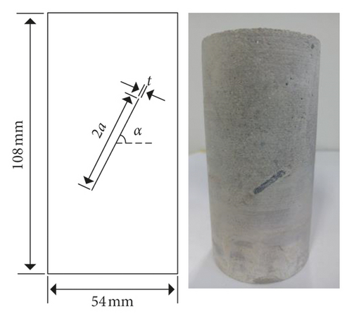
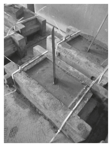
Many researchers selected model materials to fabricate rock-like samples with fissures having different geometries [22–26]. In this research, the model material was a mixture of Portland 42.5 cement, fine sand, and water with a weight ratio of 1 : 2 : 0.5. The mixture was poured into a prepared wooden mold having a size of 70 mm × 70 mm × 140 mm, and a thin steel sheet with a thickness of 1.0 mm was inserted into the mixture (Figure 2(a)). After 24 hours, samples were solidified and removed from the mold, and the steel sheet was pulled out from the mold to fabricate an open flaw. The samples were placed in a constant temperature water tank and cured for 28 days.
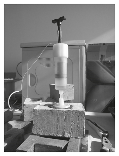
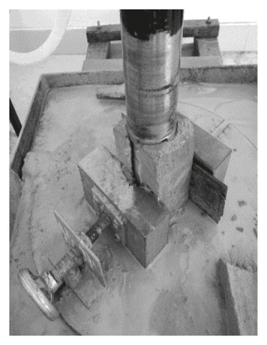
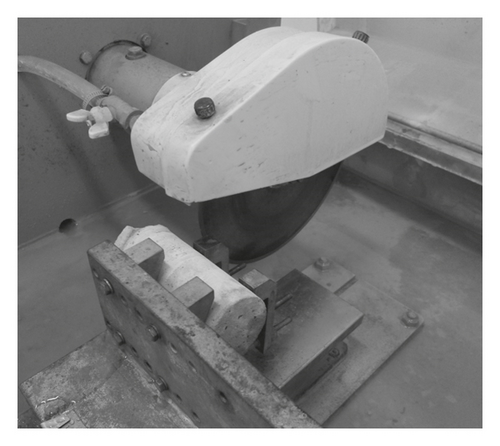
Epoxy resin was used as the grouting material. First, the plastic base was attached to the surface of the cured specimen. Second, the injection port of the syringe was inserted into the plastic base to inject the epoxy resin (Figure 2(b)). Grouting was stopped when the epoxy resin flowed out from the other side of the flaw, and the base was blocked with a plug. The sample was then inverted and left for three days. After the epoxy resin hardened, the filled specimens were drilled using a drill with an inner diameter of 54 mm (Figure 2(c)) and cut using a cutter (Figure 2(d)). Finally, the cylindrical specimens with a height of 108 mm and a diameter of 54 mm containing a single grout-infilled flaw were prepared (Figure 1).
2.2. Testing of Mechanical Properties of the Model Material and Grouting Material
Uniaxial compressive tests were carried out on the specimens made by the model material and epoxy resin, and the results showed that their uniaxial compressive strengths are 42.0 and 62.8 MPa, respectively. Triaxial compressive tests were conducted on the specimens made by the model material under different confining pressures, and the shear parameters of the model material were obtained (c = 11.09 MPa and φ = 41.60°). The shear parameters of epoxy resin were obtained by conducting direct shear tests on the specimens made by epoxy resin, and the results showed that its cohesion and internal friction angle are 30.2 MPa and 21.9°, respectively. The testing procedures of triaxial and uniaxial compressive tests and direct shear tests comply with ASTM 2004 [27], ASTM 2014 [28], and ASTM 2016 [29], respectively.
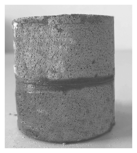
Some studies have demonstrated that the interface of two dissimilar materials, such as the surface of a grout-infilled flaw, is usually weak, and shear parameters of the interface have an influence on strengths of the specimens [30, 31]. Therefore, shear parameters of the interface between the epoxy resin and model material were obtained by conducting direct shear tests on the surface of a grout-infilled flaw. Figure 3 shows the prepared sample for direct shear tests. Test results show that the internal friction angle and cohesion of the interface were 42.5° and 2 MPa, respectively. The cohesion of the interface is much lower than that of the model material and epoxy resin.
2.3. Testing Equipment and Procedure
The equipment for triaxial compressive tests is a British-made equipment with a maximum confining pressure of 70 MPa, a maximum vertical load of 1560 kN, and an axial maximum displacement of 50 mm. The triaxial compressive test procedures are as follows: first, the confining pressure was increased to a predetermined value at a rate of 0.2 MPa/s and then maintained, and the axial pressure was imposed on the end surfaces of the rock-like specimens at a constant displacement rate of 0.01 mm/min until failure.
3. Results and Discussion
3.1. Influence of Confining Pressure and Flaw Geometry on the Failure Modes of the Specimens with a Grout-Infilled Flaw
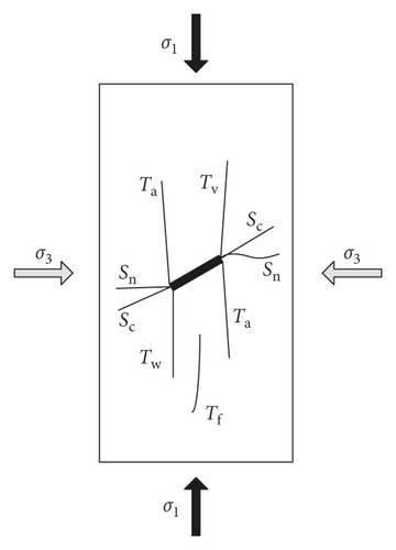
According to Yang and Huang [9] and Lajtai [32], five different crack types (Figure 4) were identified based on the crack initiation path and propagation mechanism in the rock-like specimens with a grout-infilled flaw. A type Tw crack is a tensile wing crack that initiates from the tips or at a distance from the tips of the flaw and usually propagates along the direction of the maximum principal stress. Crack type Ta is an antitensile crack that initiates from the tips of the preexisting flaw and propagates along the direction of the maximum principal stress, but it propagates in an opposing manner to that of crack type Tw. Crack type Tf is a far-field tensile crack that does not initiate from the tips of the flaw, and its propagation direction is variable depends on the loading process. Crack type Sn is a shear crack with a normal propagation direction to the major principal stress. Crack type Sc and the preexisting flaw are typically coplanar; crack type Sc is a shear crack, and its initiation direction is parallel to the direction of the preexisting flaw, but it may develop and reach the end surface of the samples.
3.2. Analysis of Failure Modes of the Specimens Having a Flaw Inclination Angle of 30°
Figure 5 shows that, for the specimens with a grout-infilled flaw having an inclination angle of 30° and length of 1 cm, at σ3 = 1.0, 3.0, and 4.0 MPa, Tw initiated from the tips of the preexisting flaw and developed along the direction of the major principal stress. As the loading continued, the propagation direction of Tw deflected, and Tw developed toward the lateral side (see samples A1 and A5) or the end of the specimen (see sample A4) and caused tensile-shear failure. At σ3 = 2.0 MPa, Sn initiated from the upper and lower tips of the flaw, and Tw initiated from the upper tip of the flaw. At σ3 = 2.5 MPa, Sn initiated from the upper tip of the flaw, and Ta initiated from the lower tip of the flaw; the combination of shear crack and antitensile crack caused the failure of the specimen. Sc was observed in all specimens with a flaw having an inclination angle of 30° and length of 2 cm. At σ3 = 1.0 and 2.0 MPa, Tw initiated from the upper or lower tip of the flaw and developed to the lateral side of the specimens. At σ3 = 2.5 MPa, Tw initiated from the middle part of the flaw and developed to the end of the specimens. As the confining pressure increased to 3.0 and 4.0 MPa, Sc led to the shear failure along the flaw plane. It indicates that, for the specimens with a flaw length of 2 cm and an inclination angle of 30°, as the confining pressure increased, the failure mode of the specimen changed from tensile-shear failure to shear failure. When the flaw length was 3 cm, the failure mode of the specimens under different confining pressures was shear failure, and the failure plane was parallel to the preexisting flaw. This shows that, for the specimens with a flaw length of 3 cm and an inclination angle of 30°, the confining pressure does not affect the failure mode of the specimens.
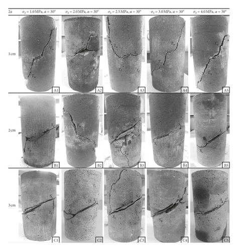
By comparing failure modes of the specimens having different flaw lengths, it can be seen that when the flaw length is 1 cm, Tw was observed in all the specimens, regardless of the confining pressure. As the flaw length increased to 3 cm, Sc was observed in all the specimens, but Tw was not observed. It indicates that, when the flaw inclination angle was 30°, the increase in flaw length suppressed the initiation of Tw and promoted the initiation of Sc.
3.3. Analysis of Failure Modes of the Specimens Having a Flaw Inclination Angle of 45°
Figure 6 shows that, for the specimens having a flaw inclination angle of 45° and flaw length of 1 cm, at σ3 = 1.0 MPa, Sc and Sn initiated from the tips of the preexisting flaw, and the failure plane of the sample manifested as an “X”-shaped shear failure. At σ3 = 2.0 MPa, Sc and Sn initiated from the tips of the preexisting flaw, and Sc ran through the whole specimens, but Sn did not. Sc led to the shear failure along the flaw plane. At σ3 = 2.5, 3.0, and 4.0 MPa, Sc initiated from the tips of the preexisting flaw and led to the shear failure of the specimens. For the specimens having a flaw inclination angle of 45° and length of 2 cm, the failure modes of the specimens were similar, and Sc resulted in the shear failure of the specimens. At σ3 = 1.0 and 2.0 MPa, Tf was observed and its extension distance was limited. At σ3 = 2.5 and 3 MPa, Sc initiated from the upper tip of the flaw and propagated along the flaw plane. As loading continued, the crack developed along the direction of the major principal stress. For the specimens having a flaw inclination angle of 45° and length of 3 cm, Sc initiated from the tips of the flaw and led to the shear failure of the specimens. At σ3 = 1.0, 2.0, and 3.0 MPa, Tf was observed in the specimens, but it had little influence on the failure mode.
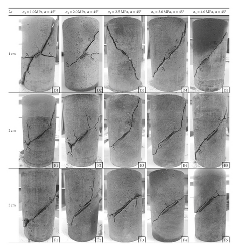
Figure 6 shows that, when the flaw inclination angle was 45°, regardless of the flaw length and the confining pressure, Sc was observed in all the specimens, and the failure modes of all the specimens are shear failure. Figure 6 shows that, when the flaw length and inclination angle were the same, the increase in the confining pressure suppresses the generation of tensile cracks.
3.4. Analysis of Failure Modes of the Specimens Having a Flaw Inclination Angle of 60°
Figure 7 shows that, for the specimens with a grout-infilled flaw having an inclination angle of 60°, the failure mode of most samples (except sample I3) was shear failure along the flaw plane, regardless of the flaw length and confining pressure. The failure mode of sample I3 was shear failure caused by Sn, and the failure plane was not parallel to the flaw plane. In the specimens G1 and G2, Sn initiated from the upper or lower tip of the flaw, but its influence was very limited. In the specimens H1 and H5, after Sc developed to a certain distance, Sn initiated from a point on the development path of Sc, and Sc appeared to split into two cracks. This phenomenon is named “bifurcation phenomenon”.
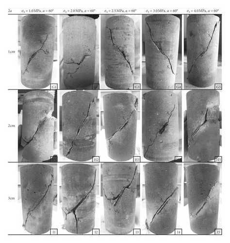
By comparing failure modes of the specimens having different flaw lengths, it can be seen that, when the confining pressure was low, the shear crack and tensile crack were observed in the specimens. When the confining pressure was large, only a shear crack was observed in the specimens. “Bifurcation phenomenon” was observed in a few specimens. Figure 7 shows that, when the flaw inclination angle is 60°, the shear crack is the main crack type, regardless of the confining pressure and flaw length.
Figures 5–7 show that there are two types of failure modes for the specimens with a single grout-infilled flaw having an inclination angle of 30°, 45°, or 60°, respectively: tensile-shear failure and shear failure. The confining pressure is the main factor controlling the failure mode of the specimens. With the increase of confining pressure, the failure mode changes from tensile-shear failure to shear failure. The larger the confining pressure, the harder it is to generate the tensile crack. In some samples, “bifurcation phenomenon” was observed, and Sc and Sn developed to the lateral side of the specimens and caused a broken block. As the flaw length increased, the shear failure was easier to occur. Regardless of the flaw geometry and confining pressure, shear failure occurred along the interface between the model material and epoxy resin, while the grouting material was not sheared and destroyed. This is because the interface between the model material and epoxy resin is a weak surface, and the shear strength of the interface is lower than that of the epoxy resin and model material.
3.5. Influence of Confining Pressure and Flaw Geometry on Mechanical Properties of the Specimens with a Grout-Infilled Flaw
3.5.1. Analysis of the Peak Strength of the Specimens with a Grout-Infilled Flaw
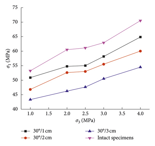
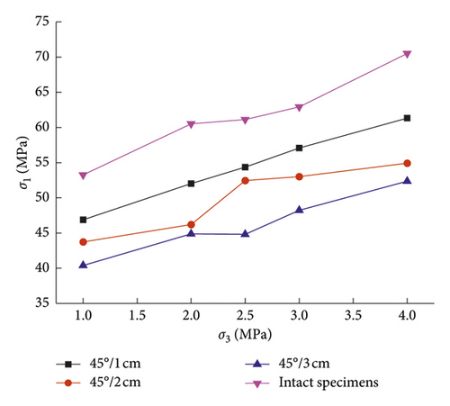
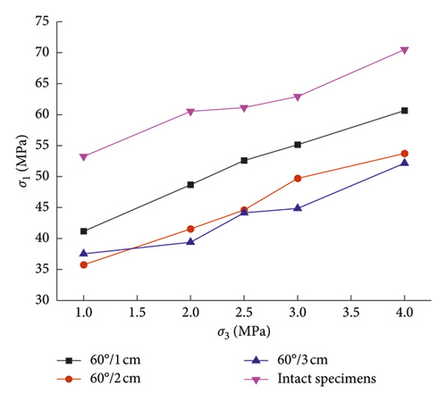
The specimens with a grout-infilled flaw show different peak strengths under the combined influence of flaw length, flaw inclination angle, and confining pressure. Figure 8 shows peak strengths of the specimens with a grout-infilled flaw and the intact specimens under various confining pressures. Under the same confining pressure, the strength of the specimens with a grout-infilled flaw is significantly lower than that of the intact specimens. It indicates that, although the grouting material has a higher strength and reduces the stress concentration around the grouted flaw (especially at the tips), the preexisting flaw still weakens the strength of the specimens. By comparing Figures 8(a)–8(c), it can be seen that, as the flaw inclination angle increases, the distance between the curve representing a flaw length of 2 cm and the curve representing a flaw length of 3 cm is reduced. Keeping the confining pressure and flaw inclination angle constant, the strength of the grouted specimen decreased as the length of the preexisting flaw increased.
3.5.2. Analysis of Shear Parameters of the Specimens with a Grout-Infilled Flaw
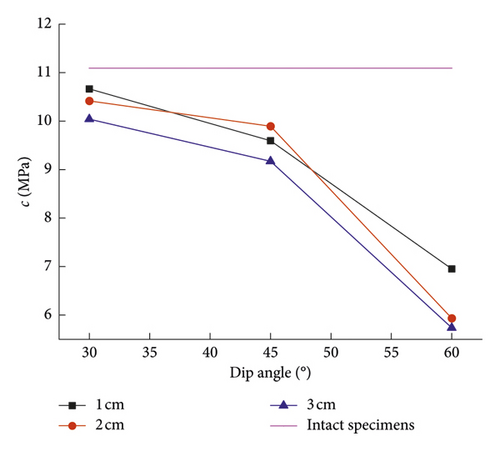
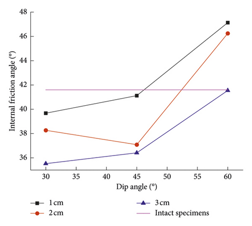
Figure 9 shows shear parameters (cohesion and internal friction angle) of the intact specimens and the specimens with a grout-infilled flaw. Figure 9 shows that, for the specimens having the same flaw length, the cohesion of the specimens decreased moderately as the flaw inclination angle increased from 30° to 45°, and the cohesion decreased sharply as the flaw inclination angle increased from 45° to 60°. The internal friction angle of the specimens increased with the increasing flaw inclination angle (except for the specimens having a flaw length of 2 cm and an inclination angle of 45°). The cohesion of the specimens with a grout-infilled flaw was lower than that of the intact specimens. The internal friction angle of the specimens having a flaw inclination angle of 30° and 45° was lower than those of the intact specimens, but the internal friction angle of the specimens having a flaw inclination angle of 60° was larger than that of the intact specimens. It indicates that the grouted flaw has an obvious influence on the shear parameters of the specimens. Figure 9 shows that, for the specimens having the same flaw inclination angle, the internal friction angle and the cohesion generally decreased as the flaw length increased. It indicates that, even though the flaw is grouted with epoxy resin of which strength is larger than the strength of the model material, an increase of the flaw length weakens the ability of samples to resist shear. This is because the failure plane of the specimens is the interface between the epoxy resin and model material, and although the strength of the epoxy resin is larger than that of the model material, the interface is a weak surface. The longer the preexisting flaw, the longer the interface; the shear resistance of the sample is reduced, which leads to a lower shear parameter.
4. Comparison with the Results of the Specimens with an Unfilled Flaw under Triaxial Compression
Sun [21] shows failure modes of the specimens with an unfilled flaw under different confining pressures. The flaw geometry set in Sun [21] is the same as the flaw geometry set in this research (2a = 1, 2, and 3 cm; α = 30° and 45°). The model material and grouting material used in Sun [21] are the same as those used in this research. The confining pressure and loading rate of the axial pressure are the same as that set in this research. Therefore, the results obtained by Sun [21] are compared with the results obtained in this research to study the effect of grouting on the mechanical properties and failure modes of the specimens under triaxial compression.
Figure 10 shows failure modes of the specimens with an unfilled flaw under the smallest confining pressure (σ3 = 1.0 MPa) and the largest confining pressure (σ3 = 4.0 MPa). When the flaw geometry is constant, failure modes of the specimens under σ3 = 4.0 MPa are the same as that of the specimens under σ3 = 1.0 MPa. It indicates that, for the specimens with an unfilled flaw, confining pressure does not change the failure modes of the specimens, which differs from the results obtained from the specimens with a grout-infilled flaw. For instance, for the specimens containing a grout-infilled flaw with a flaw length of 2 cm and an inclination angle of 30°, failure modes of the specimens changed from tensile-shear failure to shear failure as confining pressure increased (Figure 5). For the specimens with an unfilled flaw, when the flaw inclination angle and confining pressure were constant, shear failure occurs more easily in specimens with a larger flaw length, which is consistent with the conclusion obtained from the specimens with a grout-infilled flaw. For the specimens containing an unfilled flaw with a flaw length of 3 cm, Sn was observed in most of the specimens and the failure plane was not parallel to the preexisting flaw. However, the failure of most samples with a grout-infilled flaw was caused by Sc, and the failure plane was parallel to the preexisting flaw. Tensile cracks were only observed in a small number of the specimens with a grout-infilled flaw (α = 30°, 2a = 1 cm). For the specimens with an unfilled flaw, tensile cracks can be observed in the specimens with α = 30° and 2a = 1, 2, and 3 cm and those with α = 45° and 2a = 1 cm. It indicates that the grouting of epoxy resin suppresses the initiation of the tensile crack.
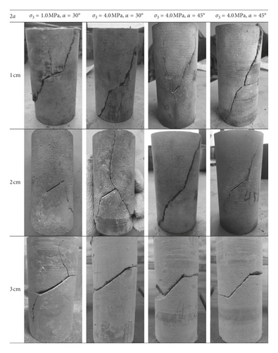
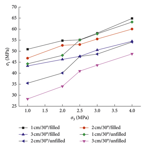
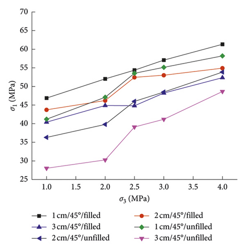
Figure 11 shows peak strengths of the specimens containing a grout-infilled flaw and unfilled flaw under different confining pressures. The strength of the specimens with a grout-infilled flaw is larger than that of the specimens containing an unfilled flaw with the same flaw geometry and under the same confining pressure. It shows that grouting of specimens improves the peak strength of the specimens under triaxial compression. Shear failure occurs easily in the specimens with grout-infilled flaw, and shear failure occurs along the interface between the model and grouting material. Compared with the surface of an unfilled flaw, grouting improves shear parameters of the interface between model material and grouting material. Therefore, the interface can sustain larger shear stress, which leads to the improvement of peak strength of the specimens. In addition, epoxy resin has a large compressive strength, and grout-infilled flaws can withstand higher compressive stress than unfilled flaw. Meanwhile, grouting reduces the stress concentration around the grouted flaw (especially at the tips), and cracks are not easy to initiate, which increases the peak strength of the specimens. Therefore, grouting improves the peak strength of the specimens under triaxial compression. When the flaw geometry is constant, strengths of the specimens with a grout-infilled flaw and unfilled flaw increase with the increasing confining pressure, indicating that grouting does not change the variation in sample strength with confining pressure. For the specimens with an unfilled flaw, as the flaw length increases, the strength of the specimens decreases significantly. However, for the grouted specimens, as the flaw length increases, the magnitude of the decrease in strength is smaller than that for the specimens with an unfilled flaw. It indicates the grouting of epoxy resin reduces the effect of flaw length on strength.
The calculated growth rate of strength for the specimens under different confining pressures is shown in Figure 12. A larger growth rate of strength indicates a better reinforcement effect. Figure 12 shows that, when the flaw geometry and confining pressure are constant, the growth rate of strength increases with increasing flaw length, which indicates a better reinforcement effect. This is because, in the case of no grouting, the longer the flaw, the lower the strength of the specimen, and the strength of the specimen can be greatly improved by grouting. From Figure 13, it can be seen that, when the flaw geometry is constant, the growth rate of the strength under a low confining pressure (σ3 = 1.0 and 2.0 MPa) is larger than that under a relatively high confining pressure (σ3 = 3.0 and 4.0 MPa). This shows that the reinforcement effect is better under a low confining pressure. Figure 12(a) shows that, when the flaw length is constant, for the specimens with a flaw inclination angle of 30°, Sgr varies little as the confining pressure increases from 2.5 MPa to 4.0 MPa. Figure 12(b) shows that, when the flaw length is constant, for the specimens with a flaw inclination angle of 45°, the amplitude in the variation of Sgr is larger than that of the samples with a flaw inclination angle of 30°. It indicates that the flaw inclination angle has an influence on the reinforcement effect.
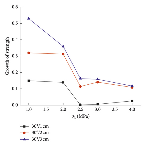
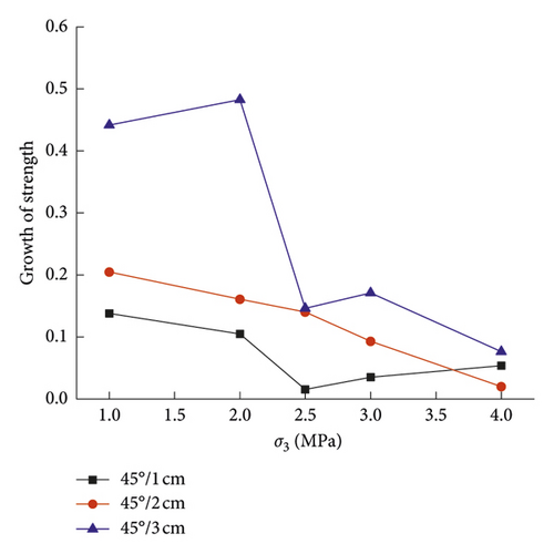
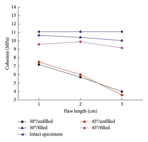
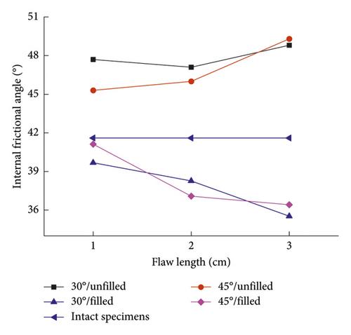
Figure 13 shows shear parameters of the specimens containing a grout-infilled flaw and unfilled flaw having different flaw geometries. Figure 13(a) shows that, when the flaw geometry is constant, the cohesion of the specimens with a grout-infilled flaw is larger than that of the specimens with an unfilled flaw. For the specimens with a grout-infilled flaw, as the flaw length increases, the change of the cohesion is small, which indicates that the flaw length has little effect on the cohesion. For the specimens with an unfilled flaw, as the flaw length increases, the cohesion decreases significantly, indicating that the flaw length greatly influences the cohesion of the samples with an unfilled flaw. It shows that grouting weakens the effect of flaw length on cohesion. Figure 13(b) shows that, when the flaw geometry is constant, the internal friction angle of the specimens with an unfilled flaw is larger than that of the specimens with a grout-infilled flaw. For the specimens with an unfilled flaw, the variation of the internal friction angle with the flaw length is different from that of the grouted sample, indicating that the grouting can change the influence of the flaw length on the internal friction angle.
5. Conclusions
- (1)
Two types of failure modes were observed in the triaxial compressive tests on the rock-like specimens with a grout-infilled flaw: tensile-shear failure and shear failure. Confining pressure has an obvious influence on the failure modes. The increase of the confining pressure suppresses the generation of the tensile crack and promotes the initiation of the shear crack. The failure mode of the specimens with a grout-infilled flaw has a tendency to move from tensile-shear failure to shear failure as the confining pressure increases.
- (2)
The flaw length and flaw inclination angle have an effect on the crack types and failure modes of the specimens with a grout-infilled flaw. As the flaw length increases, the shear failure occurs easily along the preexisting flaw plane in the specimens with a grout-infilled flaw. When the flaw inclination angle is small (α = 30°), it is easy for the tensile wing crack to initiate from the tips of the preexisting flaw.
- (3)
Epoxy resin has a larger shear strength than the model material, and it does not fail under a large plastic deformation. Therefore, under triaxial compression, the shear failure of the specimens occurred along the interface between the model material and epoxy resin, instead of cutting through the grouting material.
- (4)
The peak strength of the specimens with a grout-infilled flaw increases with the increasing confining pressure when the flaw inclination angle and flaw length are constant, while it decreases with the increasing flaw length when flaw inclination angle and the confining pressure are constant.
- (5)
Keeping the flaw length constant, the cohesion of the specimens with a grout-infilled flaw decreases as α increases from 30° to 60°, while the internal friction angle generally increases as α increases from 30° to 60°. Keeping the flaw inclination angle constant, the shear parameters generally decrease with the increasing flaw length.
- (6)
Grouting of epoxy resin suppresses the initiation of the tensile crack, which leads to the change of failure modes of the specimens. Grouting of epoxy resin can improve the peak strength of the specimens under triaxial compression. The reinforcement effect of epoxy resin is better for the specimens having a large flaw length. Moreover, the reinforcement effect for specimens under a low confining pressure (σ3 = 1.0 and 2.0 MPa) is better than that under a relatively large confining pressure (σ3 = 3.0 MPa and 4.0 MPa). Grouting of epoxy resin improves the cohesion of the specimens but reduces their internal friction angle. Grouting is often used to reinforce the dam sites of hydropower stations and the surrounding rock of tunnels. The failure mode of grouting rock mass has an important influence on the stability of rock engineering, and the findings of this study provide helpful information for the initial assessment of the grouting effect and failure mode of fractured rock masses grouted with epoxy resin.
Conflicts of Interest
The authors declare no conflicts of interest.
Authors’ Contributions
Huilin Le and Shaorui Sun conceived and designed the experiments. Haotian Fan and Feng Zhu performed the experiments. Huilin Le, Haotian Fan, and Feng Zhu analyzed the data. Huilin Le and Shaorui Sun wrote the paper.
Acknowledgments
This project was supported by the National Natural Science Foundation of China (no. 41672258 and 41102162) and Postgraduate Research & Practice Innovation Program of Jiangsu Province (no. KYCX18_0622), which is greatly appreciated. This research was also supported by “The Fundamental Research Funds for the Central Universities” (no. 2018B695X14). The Chinese Scholarship Council supported the first author of this paper to do part of this research at the University of Arizona, which is greatly appreciated.
Open Research
Data Availability
The data used to support the findings of this study are available from the corresponding author upon request.


