Modal Analysis for a Rod-Fastened Rotor considering Contact Effect Based on Double Fractal Model
Abstract
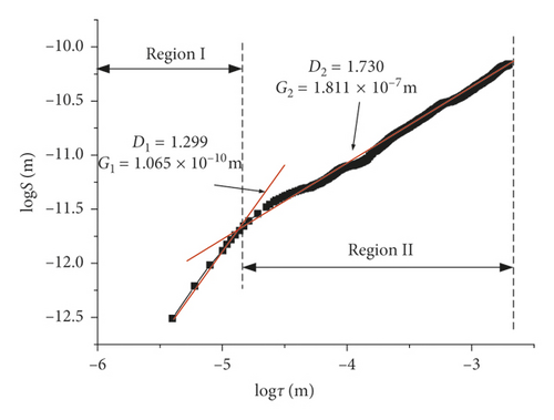
The rod-fastened rotor is the core component of the gas turbine. It comprises several discs and tie rods. The flexural stiffness of the contact interface is the key factor for rotordynamic analysis. The contact interfaces of the discs are usually manufactured by grinding. The measured contour curve of the contact interfaces of an experimental rod-fastened rotor is analyzed by the structural function method, which shows that the contact interfaces can be well described by the double fractal model with fractal dimensions D1 and D2 and the fractal roughness parameters G1 and G2. The Hertz model is used to analyze the contact of the single asperity on the contact interface. On this basis, the flexural stiffness of the contact interface considering the pretightening force and the bending moment is derived. Modal frequencies of the experimental rod-fastened rotor under different pretightening forces and the bending moment (caused by gravity) are obtained by three-dimensional finite element analysis and experimental modal tests. It is observed that the modal frequencies increase with the nominal pressure of the contact interface, and the experimental results are consistent with the calculated results.
1. Introduction
The rod-fastened rotors are widely used in aeroengines and heavy-duty gas turbines (see Figure 1). In order to avoid the damage caused by flexural vibration, it is necessary to accurately calculate the flexural vibration modal frequencies of the gas turbine rotor at the design stage. Because the rotor is not a continuous whole, the contact effect between two discs has a great influence on the dynamic characteristics. There are some researches about the dynamic performance of such structures. Klompas [1] analyzed the influence of the bending moment on the dynamic characteristic of the rotor joints in the turbomachine. Lee and Lee [2] investigated the effect of the central tie rod on the rotordynamic performances of an auxiliary power unit gas turbine rotor. Lu et al. [3] calculated the modal frequencies of a rod-fastened rotor subjected to different pretightening forces by the three-dimensional finite element method. Liu et al. [4] studied the dynamic stability of a rod-fastened rotor bearing system considering the nonuniform pretightening forces. However, the effect of the contact stiffness on the dynamic characteristic of the rod-fastened rotor was not considered.

For the contact stiffness of the contact interface, some researchers have studied the contact stiffness in microscale. Rao et al. [5] calculated the contact stiffness using the Hertz elastic contact theory and Greenwood–Williamson statistical model. He et al. [6] studied the contact stiffness of rough contact interfaces using Greenwood–Williamson model and the elastic-plastic contact model. Zhang et al. [7] identified the contact stiffness by modal test and obtained the relationship between the contact stiffness and the pretightening force. There are also some researches to analyze the flexural stiffness considering the bending moment. Isa et al. [8] established a bilinear stiffness model to calculate the flexural stiffness of a rod-fastened rotor subjected to the bending moment. Gao et al. [9] studied the effect of the bending moment and the pretightening force on the flexural stiffness of the contact interface in the rod-fastened rotor. Several researchers calculated the equivalent stiffness of bolted structures by the finite element method. Lehnhoff et al. [10, 11] calculated the equivalent stiffness of the bolted joints using the axisymmetric finite element model. Yuan et al. [12] calculated the contact stiffness and flexural stiffness of the gas turbine rotor with curvic couplings using the three-dimensional finite element model.
In the above studies, the contact stiffness is calculated using Greenwood–Williamson statistical model. However, the contact interfaces of the discs in the actual gas turbine are manufactured by grinding. Due to the different scales of plastic deformation and microfracture during processing, such machined surfaces generally have double fractal characteristic [13]. Jiang et al. [14] calculated the normal contact stiffness of the joint surface based on the fractal model and compared the theoretical calculation results with the experimental data. Buczkowski et al. [15] used the Weierstrass–Mandelbrot function to express the fractal features of the rough surface and calculated the normal contact stiffness of the isotropic rough surface during extrusion deformation.
However, there are few investigations that focus on the analysis of the flexural stiffness of the rod-fastened rotor, considering the pretightening force and the bending moment based on double fractal model. In this paper, an experimental rod-fastened rotor is designed. The contact interfaces of the rotor are grinding. The contour curve of the contact interfaces is analyzed by the structural function method, which shows that the contact interfaces have double fractal characteristic. The normal contact stiffness of the contact interface is obtained by the Hertz contact theory and the double fractal model. The flexural stiffness of the contact interface considering the pretightening force and the bending moment is also derived. Finally, the modal frequencies of the rotor under different pretightening forces are obtained by the three-dimensional finite element method and the experimental modal method, respectively. Comparing the experimental test results with the calculated results, it is found that the double fractal model is reasonable to calculate the contact stiffness of the rod-fastened rotor.
2. Theoretical Analysis
2.1. The Experimental Rod-Fastened Rotor
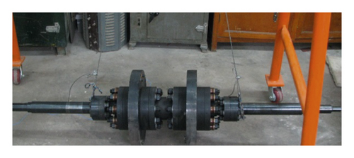
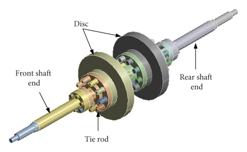
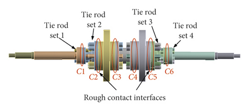
The experimental rod-fastened rotor consists of discs, a front shaft end, a rear shaft end, and nine tie rods (see Figure 2). The rotor is clamped together by the circumferentially arranged tie rods. A rough contact interface is existed between two discs of the rotor. As shown in Figure 3, there are six rough contact interfaces of C1–C6 in the rotor. The structure of the rotor is bilaterally symmetrical. The material of the rotor is 40Cr.
The elastic modulus E is 206 GPa, the density ρ is 7870 kg/m3, and the Poisson ratio v is 0.3.
2.2. The Mechanical Model of the Contact Segment in the Experimental Rod-Fastened Rotor
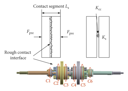
The flexural stiffness correction coefficient η represents the stiffness reduction of the contact interface to the continuous shaft. For the contact segment, η is mainly related to the pretightening force and the bending moment.
2.3. The Equivalent Flexural Stiffness of the Contact Interface Kcc
2.3.1. The Double Fractal Model of the Contact Interface in the Experimental Rod-Fastened Rotor
The contact interfaces of the experimental rod-fastened rotor are machined by grinding, and the rough contact interfaces can be regarded as isotropic. The contour curves of the contact interfaces are measured by the SJ201P surface topographer. According to the contour curve, the fractal parameters can be obtained by the structural function method.
| D1 | D2 | G1 (m) | G2 (m) | τ12 (m) | Re (μm) |
|---|---|---|---|---|---|
| 1.299 | 1.730 | 1.065 × 10⁻¹⁰ | 1.811 × 10⁻⁷ | 2.80 × 10⁻⁵ | 1.57 |
2.3.2. The Contact Model of the Double Fractal Surface
The contact of two rough surfaces can be equivalent to the contact between a rough face and a rigid face. Figure 6 shows the microcontact established between an asperity of the rough surface and opposing rigid plane. The contact asperity is assumed to be a sphere, when the small contact asperities are in the state of full plastic.
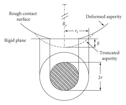
When the pretightening force is increased, the small contact asperities are merged into a large contact asperity, and the large contact asperity begins to make elastic contact. When aL ≤ ac, the contact interface is in a fully plastic contact state. When aL > ac, the contact interface enters the elastic-plastic contact state, where aL is the truncated area of the maximum contact asperity and ac is the critical truncated area where the elastic contact occurs.
-
Case 1: when ac1 < ac2, the contact asperities satisfying a < ac1 in region I are plastic deformation, and the contact asperities satisfying ac1 < a < a12 are elastically deformed.
-
Case 2: when ac1 > a12, all contact asperities in region I are plastically deformed.
-
Case 3: when ac2 < a12, all contact asperities in region II are elastically deformed.
-
Case 4: when ac2 < a12, the contact asperities satisfying a12 < a < ac2 in region II are plastically deformed, and the contact asperities satisfying a > ac2 are in the elastic deformation state.
According to the fractal parameter values of the double fractal contact interface listed in Table 1, the value of truncated areas ac1, ac2, and a12 can be obtained, respectively, and the relationship is a12 < ac2 < ac1. According to the relationship, the double fractal area of the contact interface satisfies the case 2 and case 4.
FN is determined by the pretightening force Fpre. Combining with equation (17), aL can be obtained. It will be applied to the following contact stiffness calculation.
2.3.3. The Flexural Stiffness of the Contact Interface of the Experimental Rod-Fastened Rotor
3. Application of Results and Validation
3.1. Equivalent Flexural Stiffness Keq of the Contact Segment
The flexural stiffness Kcc of the contact interface in the experimental rod-fastened rotor can be obtained by the above calculation method. Combining with equation (1), the equivalent flexural stiffness of the contact segment Keq can be obtained. Keq will be affected by the pretightening force, the bending moment, the contact area, and the length of the contact segment. To analyze the effect of above factors on Keq, the contact segment corresponding to the contact interface C2 is selected to conduct the analysis.
3.1.1. Effect of the Pretightening Force and the Bending Moment on Keq
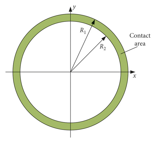
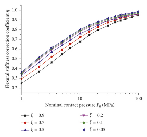
The pretightening force and the bending moment applied on the experimental rod-fastened rotor will affect the contact pressure of the contact interface. In equation (26), the flexural dimensionless load coefficient ξ is introduced to represent the influence of the pretightening force and the bending moment. The effect of the contact interface on Keq is denoted by the flexural stiffness correction coefficient η (see equation (3)). For the contact interface C2, the value of R1 and R2 is 110 mm and 70 mm, respectively. The nominal contact pressure P0 can be obtained under different pretightening forces. Figure 8 shows the effect of the pretightening force and the bending moment on η. When ξ is constant, η increases with P0, but the increasing trend gradually slows down. When P0 is constant, η decreases with the increase of ξ, which indicates that the contact interface will appear to be separated with the increase of the bending moment.
3.1.2. Effect of the Contact Area on Keq
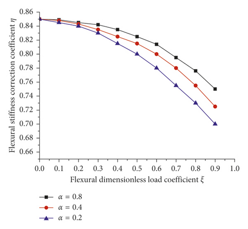
According to equation (28), the flexural stiffness Kcc is also influenced by the contact area. The outer radius R1 is given as 110 mm, and the ratio of the inner radius and outer radius α = R2/R1 is defined. The change of the contact area is obtained by changing α. Figure 9 shows the effect of the contact area on η. When ξ is constant, η increases with the decrease of α, indicating that the bending moment weakens against the bending stiffness with the increase of the contact area.
3.1.3. Effect of the Length of Contact Segment Ls on Keq
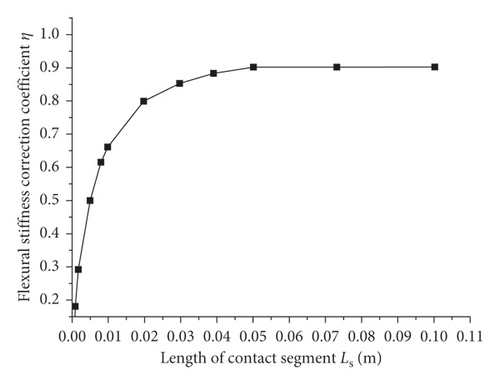
According to equations (1) and (3), η is influenced by the length Ls of the contact segment. As shown in Figure 10, when Ls is small, the length of the contact segment has a greater influence on η. When Ls reaches a certain value, η no longer increases with Ls. Therefore, it is necessary to select the appropriate length of the contact segment during the calculation. In this paper, Ls is equal to 50 mm.
3.2. Modal Analysis of the Experimental Rod-Fastened Rotor
The modal analysis is performed, considering the effect of the pretightening force and the gravity bending moment. There are six contact segments in the experimental rod-fastened rotor (see Figure 3). Due to the bilateral symmetrical structure, we only change the pretightening forces corresponding to tie rod set 2 and tie rod set 3, and the pretightening force of tie rod set 2 is equal to that of tie rod set 3. The pretightening forces corresponding to tie rod set 1 and tie rod set 4 are kept equal and constant. The different pretightening forces applied on the rotor are listed in Table 2.
| Case | Pretightening force, Fpre (N) | Nominal contact pressure, P0 (MPa) |
|---|---|---|
| 1 | 33750 | 1.492 |
| 2 | 56250 | 2.487 |
| 3 | 113400 | 5.013 |
| 4 | 228600 | 10.106 |
| 5 | 282186 | 12.475 |
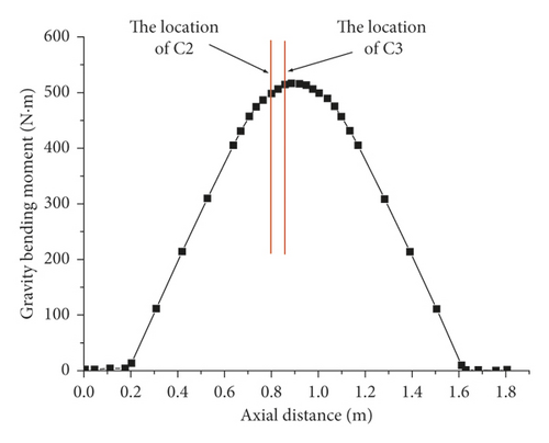
The distribution of the gravity bending moment of the experimental rod-fastened rotor is shown in Figure 11. The distribution of the gravity bending moment is bilaterally symmetric. The gravity bending moments corresponding to the positions of C2 and C3 are selected as the bending moments of the contact interfaces. The length Ls of the two contact segments is both 50 mm. According to the pretightening force listed in Table 2, the flexural stiffness correction coefficients η of the two contact segments are listed.
As shown in Table 3, η increases with the pretightening forces.
| Contact interface | Gravity bending moment (N·m) | Flexural stiffness correction coefficient, η | ||||
|---|---|---|---|---|---|---|
| Case 1 | Case 2 | Case 3 | Case 4 | Case 5 | ||
| C2 | 492 | 0.3421 | 0.4286 | 0.5657 | 0.6079 | 0.7522 |
| C3 | 512 | 0.3377 | 0.4276 | 0.5654 | 0.6075 | 0.7520 |
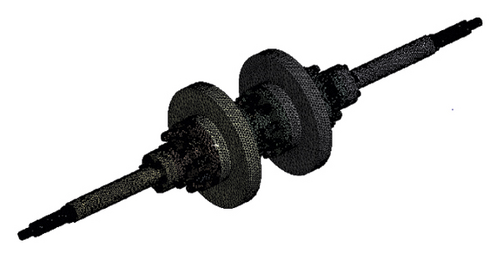
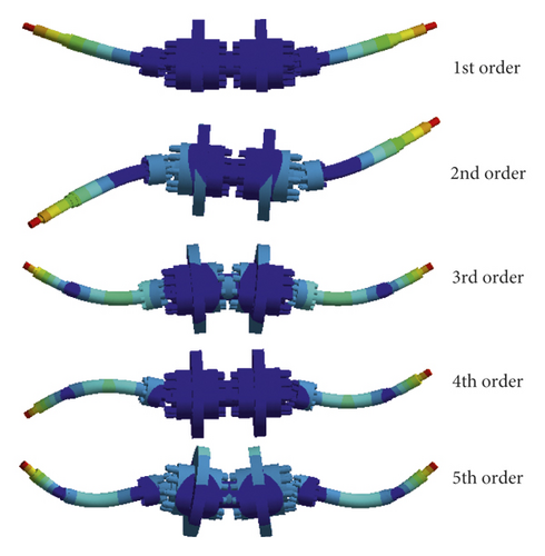
The modal analysis of the experimental rod-fastened rotor is conducted using ANSYS Version 11.0. The block Lanczos method is applied to solve the modal analysis. The three-dimensional finite element model is shown in Figure 12. The first five flexural mode shapes of the experimental rod-fastened rotor are shown in Figure 13. It can be seen that the first five mode shapes are mainly the vibration of the front and rear shaft ends, and the mode shapes of the discs are not obvious. Table 4 shows the calculated values of the first five orders of modal frequencies of the experimental rod-fastened rotor under different pretightening forces. As the pretightening force increases, the modal frequency of the rotor gradually increases. Meanwhile, the influence of the pretightening force on the 3rd and 5th order modal frequencies is greater than that of other orders. This can be explained from the mode shapes of the rotor in Figure 13. Since the 3rd and 5th order mode shapes of the discs are larger than the other orders, the frequencies of the 3rd and 5th order are more sensitive to the change of the contact stiffness.
| Case | Pretightening force (N) | Nominal contact pressure, P0 (MPa) | Dimensionless load coefficient, ξ (C2) | 1st order (Hz) | 2nd order (Hz) | 3rd order (Hz) | 4th order (Hz) | 5th order (Hz) |
|---|---|---|---|---|---|---|---|---|
| 1 | 33750 | 1.492 | 0.377 | 145.40 | 206.85 | 574.38 | 730.45 | 876.57 |
| 2 | 56250 | 2.487 | 0.226 | 145.66 | 206.99 | 577.77 | 731.33 | 880.96 |
| 3 | 113400 | 5.013 | 0.112 | 145.89 | 207.12 | 580.84 | 732.03 | 885.13 |
| 4 | 228600 | 10.106 | 0.055 | 146.04 | 207.19 | 582.78 | 732.50 | 891.86 |
| 5 | 282186 | 12.475 | 0.045 | 146.31 | 207.25 | 584.58 | 732.91 | 892.90 |
3.3. Experiment Validation
To validate the calculation method considering the pretightening force and the bending moment, a simplified experimental rod-fastened rotor is manufactured (see Figure 2(a)), and the modal experiment is conducted. The multipoint exciting method is used to measure the modal parameters of the rotor. The rotor is excited by the force hammer. An acceleration sensor is used to acquire the response signals. The range of the measured frequency is 0–3200 Hz with a frequency resolution of 1.25 Hz. The measurement system is shown in Figure 14.

In order to verify the calculated results, the pretightening forces applied on the experimental rotor are set according to Table 2. In order to reflect the effect of gravity bending moment, the experimental rotor is suspended by an elastic wire rope. The experimental results of the first five orders of modal frequencies are shown in Table 5. The comparison between the calculated and experimental results is shown in Figure 15. It can be seen that the modal frequencies gradually increase with the nominal contact pressure P0, and the change trend of the calculated results is consistent with that of the experimental results. For the 3rd order and the 5th order, the difference between the calculated and experimental results is large. Because the 3rd and 5th order mode shapes of the discs are larger than the other orders, the frequencies of the 3rd and 5th order are more sensitive to the change of the contact stiffness, which is determined by the pretightening force.
| Case | Pretightening force (N) | Nominal contact pressure, P0 (MPa) | Dimensionless load coefficient, ξ (C2) | 1st order (Hz) | 2nd order (Hz) | 3rd order (Hz) | 4th order (Hz) | 5th order (Hz) |
|---|---|---|---|---|---|---|---|---|
| 1 | 33750 | 1.492 | 0.377 | 143.5 | 204.8 | 546.3 | 723.1 | 821.3 |
| 2 | 56250 | 2.487 | 0.226 | 144.4 | 205.6 | 557.5 | 725.0 | 838.8 |
| 3 | 113400 | 5.013 | 0.112 | 146.9 | 206.9 | 569.4 | 733.1 | 848.1 |
| 4 | 228600 | 10.106 | 0.055 | 147.5 | 207.5 | 573.8 | 736.3 | 864.4 |
| 5 | 282186 | 12.475 | 0.045 | 148.1 | 208.2 | 578.5 | 737.9 | 884.8 |
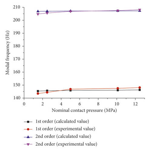
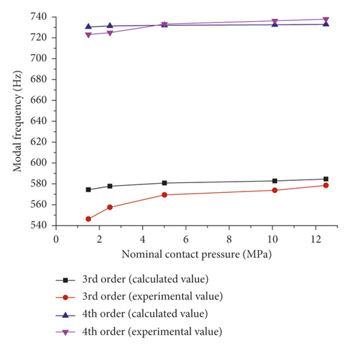
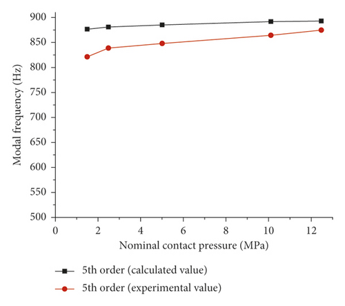
The relative errors between the calculated and experimental results are listed in Table 6. For the 3rd and 5th order, the relative errors are large when the nominal contact pressure P0 (pretightening force) is small. It could be explained by the relative errors of pretightening forces applied on the rotor being large when the pretightening forces are small. With the increase of P0, the relative errors decreased. According to the results of relative errors, it is found that the calculated results are correct.
| Nominal contact pressure, P0 (MPa) | 1.492 | 2.487 | 5.013 | 10.106 | 12.475 | |
|---|---|---|---|---|---|---|
| Dimensionless load coefficient, ξ (C2) | 0.377 | 0.226 | 0.112 | 0.055 | 0.045 | |
| Relative error (%) | 1st order | 1.31 | 0.87 | −0.69 | −1.00 | −1.22 |
| 2nd order | 0.99 | 0.67 | 0.11 | −0.15 | −0.46 | |
| 3rd order | 4.89 | 3.51 | 1.97 | 1.54 | 1.04 | |
| 4th order | 1.01 | 0.87 | 0.15 | 0.52 | 0.68 | |
| 5th order | 6.31 | 4.79 | 4.18 | 3.08 | 0.91 | |
4. Conclusions
- (1)
The double fractal model and Hertz contact theory are used to calculate the normal contact stiffness of the contact interface. The effect of the pretightening force, the bending moment, the contact area, and the length of the contact segment on the equivalent flexural stiffness Keq are analyzed. When the flexural dimensionless load coefficient ξ is constant, the flexural stiffness correction coefficient η increases with the nominal contact pressure P0 (pretightening force), but the increasing trend gradually slows down.
-
When P0 is constant, η decreases with the increase of ξ, which indicates that the contact interface will appear to be separated with the increase of the bending moment.
- (2)
The calculated and experimental modal analysis is conducted considering the pretightening force and the bending moment (due to gravity). As P0 increases, the modal frequencies increase, and the experimental results are consistent with the calculated results. Therefore, the double fractal model is reasonable to calculate the contact stiffness of the rod-fastened rotor.
Conflicts of Interest
The authors declare that they have no conflicts of interest.
Acknowledgments
This work was supported by the National Nature Science Foundation of China (no. 11872289) and the Key Project of Natural Science Foundation of Xi’an Jiaotong University (no. zrzd2017025).
Open Research
Data Availability
The data used to support the findings of this study are included within the article.


