A Three-Dimensional Guidance Logic for Continuous Curvature Path Following
Abstract
A new simple and practical guidance logic is proposed for a vehicle to follow a general continuous curvature path defined in a three-dimensional space. The proposed guidance logic is formulated in such a way that the guidance law is to generate the command acceleration such that a vehicle pursues the designed moving virtual target, and this eventually makes a vehicle to follow a desired path. The position and velocity of the virtual target are specified explicitly by introducing the concept of the projection point and the tangentially receding distance. Numerical simulations are conducted to evaluate the precise path-following capability of the proposed guidance logic.
1. Introduction
The objective of path following is to ensure a vehicle to follow a desired path without any temporal requirements [1]. Path following is an important capability of a moving vehicle, and its relevant applications can be found in wheeled robots [1], unmanned aerial vehicles [2–5], airships [6], and spacecraft [7].
A smooth path is preferable to most moving vehicles since nonsmooth motions cannot be performed without stopping and hovering capabilities of a vehicle [8]. Although some mobile robots and flying vehicles can stop or hover at a certain point, this increases the driving or flight time and may result in degraded navigation performance. A smooth path is typically the concatenation of two primitive paths: straight-line path and circular path. Smooth transitions with continuous curvature at the junction of two primitive paths are also essential for a path to be smoothly executed by a vehicle, avoiding sudden changes in the acceleration and ensuring a smooth driving or flying [9, 10]. A continuous curvature path is generated by the path planning algorithm with consideration of both the physical constraints of a vehicle and environmental constraints [11]. The continuous curvature path planning has gained a great deal of attention, and many researchers have proposed planning algorithms, which can be found in the literatures [8–13].
Once the path is generated by a path-planning algorithm, a path-following guidance algorithm is designed for a vehicle to follow the desired path. Many path-following guidance algorithms are available in the literatures, which include the conventional proportional-integral-derivative (PID) control-based method, vector field construction method [14–16], and virtual target-based method [1, 3–5, 17–22]. A comparative study between some of path-following guidance algorithms can be found in [23]. Among them, a virtual target-based method is under consideration in this paper, and this method is positioning a moving virtual target along the desired path and using the guidance or control law to follow the virtual target. Park et al. [17, 18] and Ducard et al. [19] proposed a method in which the virtual target moves along the path at a fixed distance ahead of the vehicle, which is called the look-ahead point. However, it needs another logic to ensure the distance is long enough to intersect the desired path, and it is difficult to calculate the intersection point. Moreover, the velocity of the virtual target is not explicitly determined. Cho et al. [20] extended the concept of the look-ahead point further to the look-ahead angle and proposed a new three-dimensional nonlinear path-following guidance law for differential geometric path. However, the look-ahead angle should satisfy several conditions, and it requires the radius of the virtual tube that envelops the entire path. Gates [21] determined the motion of the virtual target indirectly by introducing fictitious forces between the vehicle and the virtual target. However, this method generates complicated guidance command as pointed out in [22]. Typically, a virtual target method generates a nonlinear guidance law and can compensate a large deviation from the desired path. However, some methods in this approach are still for the paths in planar motion and are only applicable to primitive paths and their combinations, and the position and velocity of virtual target on a general three-dimensional path are not easy to determine. Park [24] proposed a new path-following guidance logic composed of the guidance law and the motion strategy of the virtual target. The guidance law is the combined pure proportional navigation guidance (PPNG) and pursuit guidance (PG) law, and the motion strategy explicitly specifies the motion of virtual target by introducing the concept of the projection point and the tangentially receding distance. The interesting aspect of this logic is that the virtual target is not always on the desired path. The proposed logic is simple and efficient, yet provides precise path following. However, the guidance logic was designed for only regular paths such as a straight-line, circular, and helical paths.
In this paper, a new extended guidance logic is presented for a continuous curvature path following based on our previous work [24]. The proposed guidance logic is general in the sense that it can be applied to any continuous curvature path in a three-dimensional space and includes the guidance logic proposed in [24] as a special case. Yet, it allows conceptually easy and practical way to determine the position and velocity of virtual target even when the desired path is a complicated curve and provides precise path following.
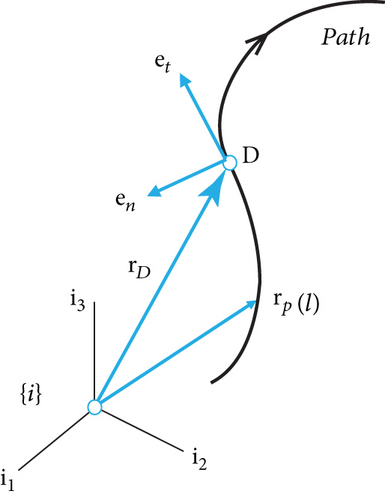
This paper is organized as follows. In the next section, a three-dimensional geometry of a continuous curvature path is presented as preliminaries to derive the proposed kinematics of a virtual target. In Section 3, the guidance law is proposed with the combined pure proportional navigation guidance (PPNG) and pursuit guidance (PG) law. In Section 4, the motion of virtual target is specified explicitly as a function of the geometry of the desired path and position and velocity vectors of the vehicle. It starts with a general continuous curvature path and moves on to special paths such as a straight-line path and a circular path. In Section 5, numerical simulations are performed to demonstrate the performance of the proposed guidance logic. Conclusions are given in Section 6.
2. Geometry of a Continuous Curvature Path
3. Design of Guidance Law
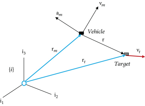
The proposed path-following guidance logic is composed of the guidance law and the motion strategy of virtual target. The goal of the guidance logic here is to generate the command acceleration such that a vehicle pursues the moving virtual target and eventually enables a vehicle to follow a desired path. This is an important difference compared to that of the missile guidance law in which the goal is to intercept a target.
4. Design of Virtual Target Motion
The proposed strategy for specifying the motion of virtual target in our previous work [24] is simple and practical. In this strategy, a virtual target is proposed to be positioned on the tangent line at the point D with a tangentially receding distance R0 ahead of that point as illustrated in Figure 3, where the point D is the nearest projection point of a vehicle position onto the desired path. Note that the virtual target is not positioned on the path, which is the main difference between the proposed and the conventional methods.
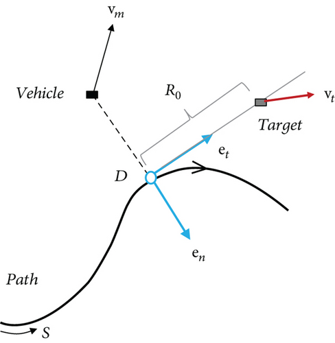
The velocity of a virtual target is computed using the velocity of the projection point, which depends on both the velocity of vehicle and the geometry of desired path. In this paper, the desired path is assumed to be designed by a path-planning algorithm such that it satisfies the maximum curvature constraint of the vehicle considering the vehicle maneuvering limitations.
In this section, the strategy of [24] is extended to a general continuous curvature path, and the motion of virtual target is explicitly determined as a function of the geometry of the desired path and position and velocity vectors of a vehicle. It starts with a general continuous curvature path and moves on to special paths such as a straight-line path and a circular path.
4.1. General Continuous Curvature Path
Therefore, with the proportional gain of N = 1, the guidance law produces the command acceleration that is the same to the instantaneous centripetal acceleration of a path with curvature κ. Note that pursuit guidance (PG) law generates zero command acceleration, which means that PG law makes no contribution in the equilibrium state.
The navigation gains N, h and the tangentially receding distance R0 between the virtual target and the projection point are the design choice of the proposed guidance logic. The influence of these values can be investigated by a linear analysis similar to the method in [17, 18]. Figure 4 shows a linearization situation with assumption that the vehicle motion is perturbed from the equilibrium state. In Figure 4, d denotes the cross-track error.
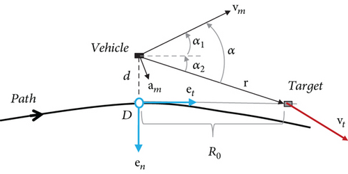
Equation (28) implies that with a proportional gain of N = 1, the cross-track error dynamics is a second-order system and the track error eventually goes to zero. The damping ratio and natural frequency are determined by PD guidance gain and the ratio of the vehicle speed and the tangentially receding distance R0, which are and . Note that the cross-track error dynamics is at least a critically damped system.
The proposed guidance logic for a general continuous curvature path following is summarized in Table 1.
| am(t) ← guidance logic(h, R0, rp(l), rm(t), vm(t)) | |
|---|---|
| 1 | Determine the nearest projection point →l∗, rD = rp(l∗) |
| 2 |
at l = l∗ |
| 3 |
at l = l∗ |
| 4 |
at l = l∗ |
| 5 |
at l = l∗ |
| 6 | If κ = 0, en = 0 else
at l = l∗ |
| 7 | rt = rD + R0et |
| 8 |
|
| 9 | r = rt − rm |
| 10 | v = vt − vm |
| 11 | R2 = r · r |
| 12 |
|
In the next two subsections, the motion strategy of virtual target for a general continuous curvature path is applied to two primitive paths: straight-line path and circular path. Since geometries of these paths are simple, the resulting motions of virtual target are also simple and turn out to be the same to the ones in [24].
4.2. Special Case 1: Straight-Line Path
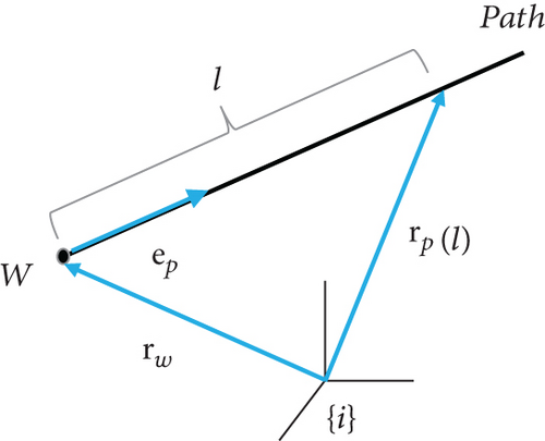
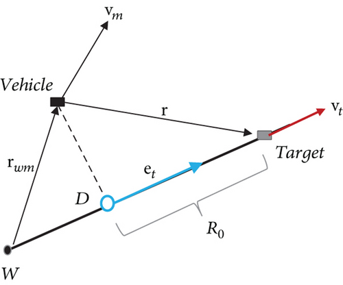
4.3. Special Case 2: Circular Path
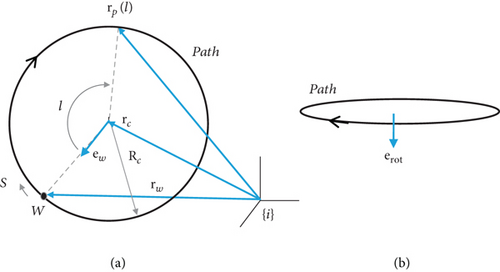
Figure 8 illustrates the pursuit geometry of the vehicle and virtual target for circular path, where rcm = rm − rc is the relative position vector of vehicle from the center of circle to a vehicle.
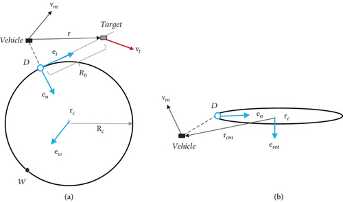
Thus, the position and velocity vectors are the same those in [24].
5. Simulations
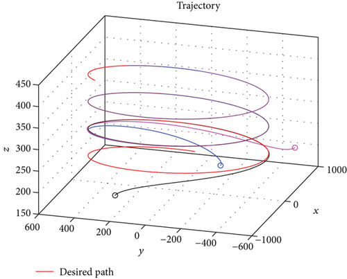
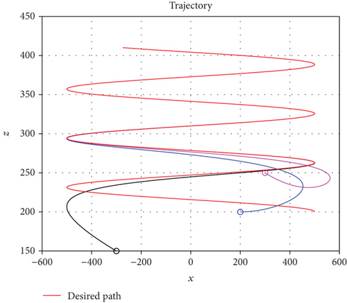
The numerical simulations are conducted to evaluate the proposed path-following guidance logic in this section. The three-dimensional path of a vehicle is assumed to be given to the vehicle a priori. The vehicle is modeled as a point mass flying at a constant speed of 20 m/sec. The tangentially receding distance R0 is chosen as 300 m, step size β = 10−6, and N = 1 and h = 1 are used in simulations.
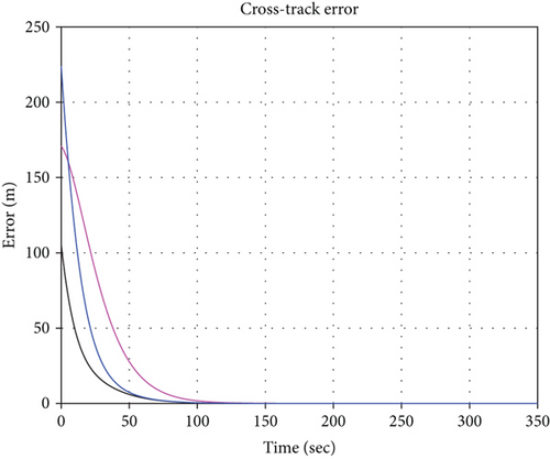
In the simulations, two scenarios are considered and the results are shown in Figures 9–13. In the first scenario, the vehicle begins at various initial positions and poses and is supposed to fly along the helical path considered in [24]. The helical path is defined on a vertical cylinder of radius 500 m, having pitch of L = 10(2π) m. The initial conditions used in the first scenario are summarized in Table 2. Figure 9 shows that the proposed logic can track the desired helical path without any following errors despite the large initial deviations from the path. The trajectories of cross-track error are shown in Figure 10.


| Line colour | Initial positions (m) | Initial headings ψ and flight path angles γ (deg) |
|---|---|---|
| Blue | x = 200, y = −200, z = 200 | ψ = 0, γ = 0 |
| Magenta | x = 300, y = −600, z = 250 | ψ = 30, γ = −10 |
| Black | x = −300, y = 300, z = 150 | ψ = 200, γ = 10 |
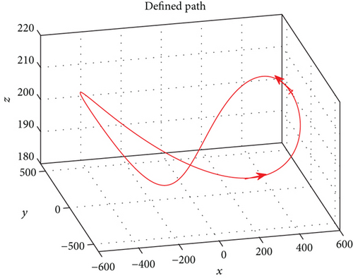
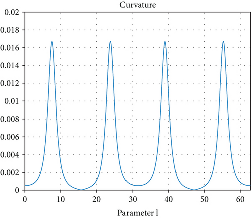
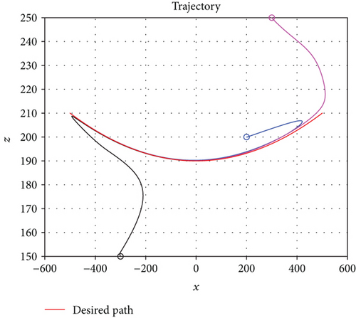
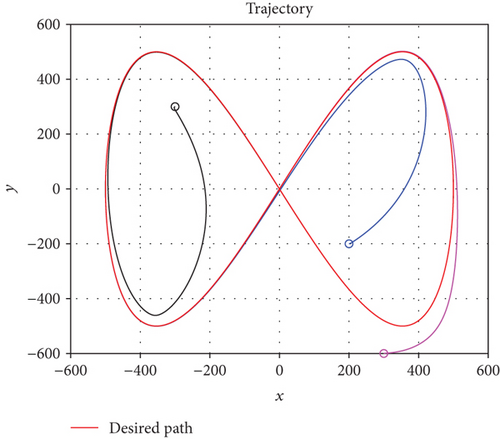
Figure 11 illustrates the defined path and its curvature as a function of parameter l. In this scenario, the vehicle begins at various initial positions and poses and is supposed to fly along the defined path. The initial conditions used in this scenario are the same to those of the first scenario as in Table 2.
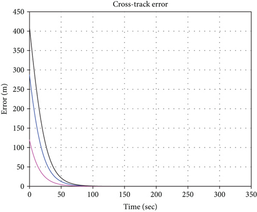
Figure 12 shows how the proposed guidance logic can successfully track this path without any following error. The trajectories of cross-track error are shown in Figure 13, which verifies that all errors converge to zero as expected.
6. Conclusions
A new simple and practical guidance logic is presented for a vehicle to follow a general continuous curvature path defined in a three-dimensional space. The proposed guidance logic is general in the sense that it can be applied to any continuous curvature path and includes the guidance logic proposed in [24] as a special case.
The proposed guidance logic is composed of the guidance law and motion strategy of the virtual target. The guidance law is a combination of the pure proportional navigation guidance (PPNG) and the pursuit guidance (PG) law, and the motion strategy explicitly specifies the motion of virtual target by introducing the concept of the projection point and the tangentially receding distance. The proposed guidance logic is formulated in such a way that the guidance law is to generate the command acceleration such that a vehicle pursues the designed moving virtual target, and this eventually makes a vehicle to follow a desired path.
The numerical simulations are conducted to evaluate the proposed path-following guidance logic. For both regular helical path and a general continuous curvature path defined in a three-dimensional space, the proposed logic shows the precise path-following capability.
Conflicts of Interest
The author declares that there is no conflict of interest regarding the publication of this paper.
Acknowledgments
This research was supported by the Basic Science Research Program through the National Research Foundation of Korea (NRF) funded by the Ministry of Education (NRF-2016R1D1A1B03934475).
Open Research
Data Availability
All data used to support the findings of this study are available from the corresponding author upon request.


