Free Vibrations of an Elastically Restrained Euler Beam Resting on a Movable Winkler Foundation
Abstract
The traditional theory of beam on elastic foundation implies a hypothesis that the elastic foundation is static with respect to the inertia reference frame, so it may not be applicable when the foundation is movable. A general model is presented for the free vibration of a Euler beam supported on a movable Winkler foundation and with ends elastically restrained by two vertical and two rotational springs. Frequency equations and corresponding mode shapes are analytically derived and numerically solved to study the effects of the movable Winkler foundation as well as elastic restraints on beam’s natural characteristics. Results indicate that if one of the beam ends is not vertically fixed, the effect of the foundation’s movability cannot be neglected and is mainly on the first two modes. As the foundation stiffness increases, the first wave number, sometimes together with the second one, firstly decreases to zero at the critical foundation stiffness and then increases after this point.
1. Introduction
In most previous studies on transverse vibrations of beams, end supports have usually been simplified as rigid restraints such as hinged, fixed, free, or sliding, neglecting the elasticity of end supports. This assumption is certainly convenient for establishing and analyzing the beam theory, while may bring errors or mistakes in some cases. As is known to all, all structural materials possess elasticity to some extent. So, only when the stiffness of end supports is much larger than that of the beam can the assumption of rigid restraints be reasonable. However, in practice, this prerequisite usually cannot be satisfied very well, for example, a submarine pipeline laid on a soft seabed [1] and a girder bridge supported on highly flexible piers [2], for which the elasticity of end supports has to be considered. Till now, a considerable amount of research has been performed on vibration analysis of beams with elastic restraints (e.g., [3–10]), and the influence of stiffness of flexible restraints on beam vibrations has been found significant.
Structural elements that can be represented as a beam supported on an elastic foundation have wide applications in numerous aspects of engineering. Weaver et al. [11] proposed a vibration model for a rigidly restrained beam resting on elastic foundations and derived its general solution. This together with other works sparked off a surge of research in this area that continues in various guises to this day (e.g., [12–18]). And, more recently, the flexibility of end supports of beams on elastic foundation has aroused universal concern of researchers [19–22] and was also found non-negligible in engineering practice. However, the elastic foundation was usually considered to be fixed with the inertia reference frame in all aforementioned studies of rigidly or elastically restrained beams supported on elastic foundations. To the best of the authors’ knowledge, there is hardly any work done for elastically restrained beams resting on movable elastic foundations, at which some structural elements in the field of engineering can be represented.
We consider in this paper a Euler beam, for simplicity, supported on a movable massless Winkler foundation and with ends elastically restrained by two vertical and two rotational springs, which is one of the most common structures in building and bridge engineering. In Section 2, a general vibration model is developed for the beam. Then, the frequency equations and corresponding mode shapes of the model are analytically derived in Section 3 and can degenerate into many other classical ones. Section 4 presents some numerical examples to study the effects of the movable Winkler foundation as well as elastic restraints on natural characteristics. Finally, some conclusions are summarized in Section 5.
2. Formulation of the Vibration Model
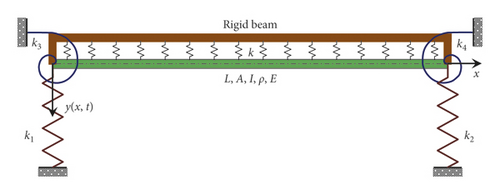
Let us consider a uniform straight Euler beam supported on a movable elastic foundation as shown in Figure 1, where L, A, I, ρ, and E are the span, cross-sectional area, cross-sectional moment of inertia, beam density, and Young’s modulus of elasticity, respectively. Ends of the Euler beam are elastically restrained by two vertical and two rotational springs with k1 and k2 being the left- and right-end transverse (or vertical) restraint stiffness, respectively, and k3 and k4 the left- and right-end bending restraint stiffness, respectively. The movable Winkler foundation is represented as a rigid massless beam together with distributed springs with a stiffness of k and is plotted above the beam for a clear visibility. As shown in Figure 1, both ends of the rigid beam are hinged to the ones of the Euler beam. So, the Winkler foundation will move vertically and/or rotationally together with the ends of the Euler beam, while has constraint on neither the Euler beam nor the elastic supports. The coordinate system is also shown in Figure 1, where the x axis is defined as the centroidal axis of the Euler beam at its original or static position, and the left end of the beam is located at x = 0. y(x, t) denotes the absolute transverse displacement of the beam relative to the x axis.
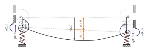
The transverse displacements as well as end forces of the Euler beam are detailed in Figure 2 where the movable Winkler foundation is omitted for a clear show. The dotted line A′B′ is the beam’s original or static position, the dashed line AB is the position of the rigid beam due to the elastic supports, and the solid curved AB is the beam’s final position. y(x, t) = the absolute displacement, u(x, t) = the flexural or relative displacement, and g(x, t) = the rigid-body or carrier displacement. y(0, t) and y(L, t) are the left- and right-end transverse displacement, respectively. All displacement components are supposed to be elastic and linear, hence satisfying the superposition principle. So, y(x, t), u(x, t), and g(x, t) can all be considered to act in the same direction, i.e., the vertical direction. Q(0, t) and Q(L, t) denote the shears at two ends, and M(0, t) and M(L, t) denote the end moments. All forces act in their positive direction.
Here and evermore, for convenience, ((∂M(0, t))/∂x) = ((∂M(x, t))/∂x)|x=0, ((∂M(L, t))/∂x) = ((∂M(x, t))/∂x)|x=L, and so forth.
Equations (9) and (7a)–(7d) are just the dimensionless free-vibration equation and corresponding boundary conditions for the elastically restrained Euler beam resting on a movable Winkler foundation.
3. Frequency Equations and Mode Shapes
3.1. Frequency Equations
In other words, only when κ satisfies equation (29) can ωc be one of the natural frequencies of the structure. We call the positive real root of equation (29) the critical foundation stiffness κc. It should be noted that the number of κc may be zero, one or two depending on the values of κ1, κ2, κ3, and κ4.
3.2. Mode Shape Functions
Clearly, the afore-obtained frequency equations (22) and (25) are both transcendental ones that have to be solved numerically by the bisection method [23]. After solving for the frequency and the corresponding mode shape, equation (19) or (24) can be determined. For each root of the frequency, there exists one mode shape of vibration which can be obtained as follows.
4. Calculations and Discussion
4.1. Validation of the Model when κ = 0
The afore-obtained model can degenerate into other ones by setting κ and/or κi (i = 1,2,3,4) to zero or infinity. κ = 0 means omitting the elastic foundation and κ = infinity corresponds to a rigid beam. Setting κ1 = κ3 = 0 (or κ2 = κ4 = 0) yields a free end. Similarly, a pinned end is achieved by setting κ1 = infinity and κ3 = 0 (or κ2 = infinity and κ4 = 0), a sliding end by setting κ1 = 0 and κ3 = infinity (or κ2 = 0 and κ4 = infinity), and a fixed end by setting κ1 = κ3 = infinity (or κ2 = κ4 = infinity). Table 1 shows the frequency equations and corresponding constants in mode shapes for ten degenerate cases with κ = 0 to validate the present model. They are exactly the same as those given by Blevins and Plunkett [24]. And, Table 2 presents the first five dimensionless wave numbers numerically obtained for the above ten degenerate cases.
| Case ∗ | Frequency equation | c1 | c2 | c3 | c4 |
|---|---|---|---|---|---|
| Sl-Fi | sin(a)cosh(a) + cos(a)sinh(a) = 0 | 0 | 1 | 0 | (sin(a)sinh(a) + cos(a)cosh(a) + 1)/(sin(a)sinh(a) − cos(a)cosh(a) − 1) |
| Fr-Sl | sin(a)cosh(a) + cos(a)sinh(a) = 0 | 1 | (cos(a) − cosh(a))/(sin(a) + sinh(a)) | 1 | (cos(a) − cosh(a))/(sin(a) + sinh(a)) |
| Fr-Fi | 1 + cos(a)cosh(a) = 0 | 1 | −((sin(a) + sinh(a))/(cos(a) + cosh(a))) | 1 | −((sin(a) + sinh(a))/(cos(a) + cosh(a))) |
| Pi-Sl | cos(a)cosh(a) = 0 | 1 | 0 | 0 | 0 |
| Sl-Sl | sin(a)sinh(a) = 0 | 0 | 1 | 0 | 0 |
| Pi-Pi | sin(a)sinh(a) = 0 | 1 | 0 | 0 | 0 |
| Fr-Fr | cos(a)cosh(a) − 1 = 0 | 1 | (cos(a) − cosh(a))/(sin(a) + sinh(a)) | 1 | (cos(a) − cosh(a))/(sin(a) + sinh(a)) |
| Fi-Fi | cos(a)cosh(a) − 1 = 0 | 1 | −((sin(a) − sinh(a))/(cos(a) − cosh(a))) | −1 | −((sin(a) − sinh(a))/(cos(a) − cosh(a))) |
| Fr-Pi | sin(a)cosh(a) − cos(a)sinh(a) = 0 | 1 | −((sin(a) + sinh(a))/(cos(a) + cosh(a))) | 1 | −((sin(a) + sinh(a))/(cos(a) + cosh(a))) |
| Pi-Fi | sin(a)cosh(a) − cos(a)sinh(a) = 0 | 1 | 0 | −(sin(a)/sinh(a)) | 0 |
- ∗Here and evermore, for convenience, Fr = free, Pi = pinned, Sl = sliding, and Fi = fixed.
| Case | a1 | a2 | a3 | a4 | a5 |
|---|---|---|---|---|---|
| Sl-Fi | 2.3650204 | 5.4978039 | 8.6393798 | 11.7809725 | 14.9225651 |
| Fr-Sl | 2.3650204 | 5.4978039 | 8.6393798 | 11.7809725 | 14.9225651 |
| Fr-Fi | 1.8751041 | 4.6940911 | 7.8547574 | 10.9955407 | 14.1371684 |
| Pi-Sl | 1.5707963 | 4.7123890 | 7.8539816 | 10.9955743 | 14.1371669 |
| Sl-Sl | 3.1415927 | 6.2831853 | 9.4247780 | 12.5663706 | 15.7079633 |
| Pi-Pi | 3.1415927 | 6.2831853 | 9.4247780 | 12.5663706 | 15.7079633 |
| Fr-Fr | 4.7300407 | 7.8532046 | 10.9956078 | 14.1371655 | 17.2787597 |
| Fi-Fi | 4.7300407 | 7.8532046 | 10.9956078 | 14.1371655 | 17.2787597 |
| Fr-Pi | 3.9266023 | 7.0685827 | 10.2101761 | 13.3517688 | 16.4933614 |
| Pi-Fi | 3.9266023 | 7.0685827 | 10.2101761 | 13.3517688 | 16.4933614 |
4.2. Effects of the Movable Foundation on Rigidly Restrained Beams
When κ = 0, by setting κi (i = 1,2,3,4) to zero or infinity, the present model can degenerate into those of beams resting on a movable Winkler foundation and with classical rigid end conditions. These models are in general different from those of beams resting on a static Winkler foundation and with the same end conditions, i.e., the traditional Winkler foundation beams. Table 3 presents the frequency equations and corresponding constants in mode shapes of the former models. However, for the latter ones, the frequency equations and corresponding constants in mode shapes are exactly the same as those of beams with κ = 0 and with the same end conditions as shown in Table 1 except that the wave number a equals or instead of .
| ω | Case | Frequency equation | c1 | c2 | c3 | c4 |
|---|---|---|---|---|---|---|
| ω > ωc | Sl-Fi | a[sin(a)cosh(a) + cos(a)sinh(a)] + r2[cos(a) − cosh(a) − sin(a)sinh(a)] = 0 | 1 | c2,S1Fi ∗ | 1 | c4,S1Fi ∗ |
| Fr-Sl | a[sin(a)cosh(a) + cos(a)sinh(a)] + r2[cos(a) − cosh(a) − sin(a)sinh(a)] = 0 | 1 | (cos(a) − cosh(a))/(sin(a) + sinh(a)) | 1 | (cos(a) − cosh(a))/(sin(a) + sinh(a)) | |
| Fr-Fi | a[1 + cos(a)cosh(a)] − r2[sin(a) + sinh(a)] = 0 | 1 | −((sin(a) + sinh(a))/(cos(a) + cosh(a))) | 1 | −((sin(a) + sinh(a))/(cos(a) + cosh(a))) | |
| Pi-Sl | 2a cos(a)cosh(a) − r2[sin(a)cosh(a) + cos(a)sinh(a)] = 0 | 1 | 0 | cos(a)/cosh(a) | 0 | |
| Sl-Sl | a sin(a)sinh(a) + r2[sin(a) − sinh(a) − sin(a)cosh(a) + cos(a)sinh(a)] = 0 | 1 | c2,S1S1 ∗ | 1 | c4,S1S1 ∗ | |
| Pi-Pi | sin(a)sinh(a) = 0 | 1 | 0 | 0 | 0 | |
| Fr-Fr | cos(a)cosh(a) − 1 = 0 | 1 | (cos(a) − cosh(a))/(sin(a) + sinh(a)) | 1 | (cos(a) − cosh(a))/(sin(a) + sinh(a)) | |
| Fi-Fi | cos(a)cosh(a) − 1 = 0 | 1 | −((sin(a) − sinh(a))/(cos(a) − cosh(a))) | 1 | −((sin(a) − sinh(a))/(cos(a) − cosh(a))) | |
| Fr-Pi | sin(a)cosh(a) − cos(a)sinh(a) = 0 | 1 | −((sin(a) + sinh(a))/(cos(a) + cosh(a))) | 1 | −((sin(a) + sinh(a))/(cos(a) + cosh(a))) | |
| Pi-Fi | sin(a)cosh(a) − cos(a)sinh(a) = 0 | 1 | 0 | −(sin(a)/sinh(a)) | 0 | |
| ω > ωc | Sl-Fi | a[sin(2a) + sinh(2a)] − r2[sin(a) + sinh(a)]2 = 0 | c1,S1Fi ∗∗ | 1 | 1 | −(2a)/r2 |
| Fr-Sl | a[sin(2a) + sinh(2a)] − r2[sin(a) + sinh(a)]2 = 0 | 0 | 1 | 1 | c4,FrS1 ∗∗ | |
| Fr-Fi | a[cos(2a) + cosh(2a) + 2] − 2r2[sin(a)cosh(a) + cos(a)sinh(a)] = 0 | 0 | 1 | 1 | c4,FrFr ∗∗ | |
| Pi-Sl | r2[sin(2a) + sinh(2a)] − 2a[cos(2a) + cosh(2a)] = 0 | 0 | 1 | c3,PiS1 ∗∗ | 0 | |
| Sl-Sl | r2[sin(a) + sinh(a)] − a[cos(a) + cosh(a)] = 0 | c1,S1S1 ∗∗ | 1 | 1 | c4,S1S1 ∗∗ | |
| Others | — ∗∗∗ | — | — | — | — | |
| ω = ωc | Sl-Fi | a = 0 and κ = 240/7 | 1 | −5 | 0 | (4(κ + 30))/κ |
| Fr-Sl | a = 0 and κ = 240/7 | 1 | −2.5 | 0 | 0 | |
| Fr-Fi | a = 0 and κ = 120/11 | 1 | −5 | 0 | 0 | |
| Pi-Sl | a = 0 and κ = 7.5 | 1 | 0 | −10 | 0 | |
| Sl-Sl | a = 0 and κ = 120 | 1 | −2.5 | 0 | (1.5(κ + 80))/κ | |
| Others | — | — | — | — | — | |
- ∗c2,SlFi = (2a cosh(a) − r2[sin(a) + sinh(a)])/r2[cos(a) − cosh(a)], c4,SlFi = (r2[sin(a) + sinh(a)] − 2a cos(a))/r2[cos(a) − cosh(a)], c2,SlSl = (2a sinh(a) + r2[1 + cos(a) − cosh(a) − sin(a)sinh(a) − cos(a)cosh(a)])/r2[sin(a) − sinh(a) − sin(a)cosh(a) − cos(a)sinh(a)], and c4,SlSl = (r2[1 − cos(a) + cosh(a) + sin(a)sinh(a) − cos(a)cosh(a)] − 2a sin(a))/r2[sin(a) − sinh(a) − sin(a)cosh(a) + cos(a)sinh(a)]. ∗∗c1,SlFi = (r2[sin(a)cosh(a) + cos(a)sinh(a)] − 2a cos(a)cosh(a))/−r2sin(a)sinh(a), c4,FrSl = (r2[cos(2a) + cosh(2a) − 2] + 2a[sin(2a) − sinh(2a)])/2[cos(a) − cosh(a)]{r2[sin(a) + sinh(a)] − 2a[cos(a) + cosh(a)]}, c4,FrFi = (2a[sin2(a) + sinh2(a)])/2r2sin(a) − a[sin(2a) + sinh(2a)], c3,PiSl = (2a sinh(2a) + r2[cos(2a) − 1])/2a sinh(2a) − r2[cos(2a) − 1], c1,SlSl = (2a[sin(a)cosh(a) + cos(a)sinh(a)] − r2[sin(a) + sinh(a)]2)/ − r2[sin(a) + sinh(a)][cos(a) − cosh(a)], and c4,SlSl = (r2[sinh2(a) − (a)] + 2a[sin(a)cosh(a) − cos(a)sinh(a)])/r2[sin(a) + sinh(a)][cos(a) − cosh(a)]. ∗∗∗: “−” = none.
Comparing Table 1 with 3 shows that movability of the foundation has serious influence on the first five cases, i.e., Sl-Fi, Fr-Sl, Fr-Fi, Pi-Sl, and Sl-Sl, while seems to have no influence on the other five cases. To show the influence quantitatively, Table 4 compares the first five wave numbers numerically obtained for the above five cases with a static and those with a movable Winkler foundation of stiffness κ = 100, and accordingly, only the first four mode shapes are given in Figures 3(a)–3(e) for a clear show. Results indicate that the influence is mainly on the first two modes and may be opposite for different cases, for example, for the case of Sl-Fi, the first wave number decreases from 2.3650204 of static foundation to 1.9669491 of movable foundation, while for the case of Fr-Fi, it increases from 1.8751041 to 2.2255349.
| Case | Foundation | a1 | a2 | a3 | a4 | a5 |
|---|---|---|---|---|---|---|
| Sl-Fi | Static | 2.3650204 | 5.4978039 | 8.6393798 | 11.7809725 | 14.9225651 |
| Movable | 1.9669491 | 5.5014690 | 8.6369097 | 11.7810633 | 14.9224023 | |
| Fr-Sl | Static | 2.3650204 | 5.4978039 | 8.6393798 | 11.7809725 | 14.9225651 |
| Movable | 1.9669491 | 5.5014690 | 8.6369097 | 11.7810633 | 14.9224023 | |
| Fr-Fi | Static | 1.8751041 | 4.6940911 | 7.8547574 | 10.9955407 | 14.1371684 |
| Movable | 2.2255349 | 4.7293245 | 7.8514919 | 10.9961585 | 14.1369917 | |
| Pi-Sl | Static | 1.5707963 | 4.7123890 | 7.8539816 | 10.9955743 | 14.1371669 |
| Movable | 2.0902242 | 4.6938582 | 7.8523471 | 10.9952652 | 14.1370786 | |
| Sl-Sl | Static | 3.1415927 | 6.2831853 | 9.4247780 | 12.5663706 | 15.7079633 |
| Movable | 2.0078977 | 6.2831853 | 9.4221148 | 12.5663706 | 15.7077544 | |
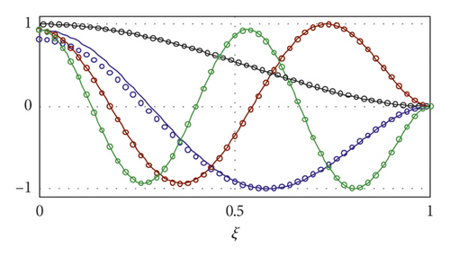
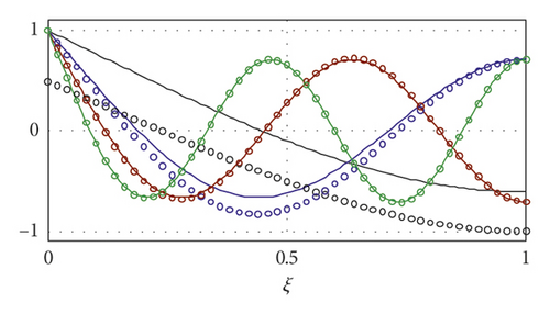
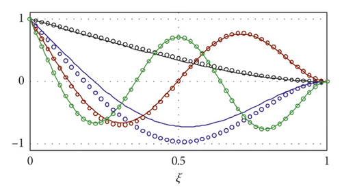
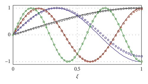
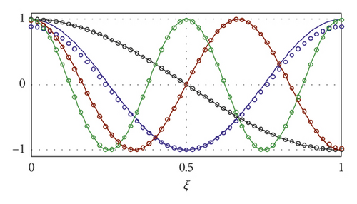
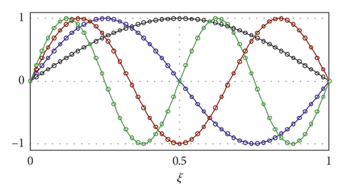
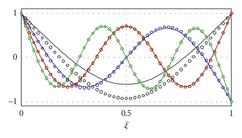
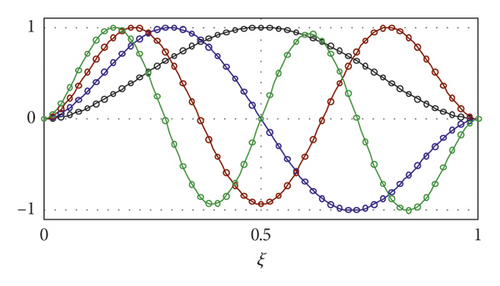
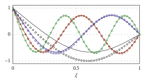
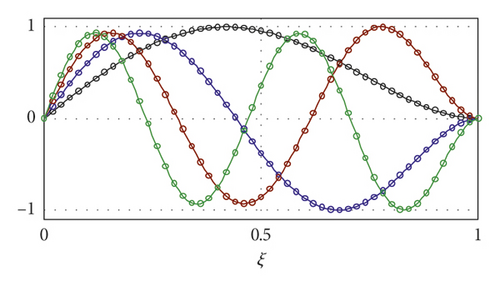
As stated above, movability of the foundation has no influence on wave number for the other five cases, i.e., Pi-Pi, Fr-Fr, Fi-Fi, Fr-Pi, and Pi-Fi, because the frequency equations are not changed. However, it may not be true for the mode shapes as shown in Figures 3(g) and 3(i) in which the first mode shape of movable foundation differs heavily from that of static foundation because of the change of shape function as shown in Tables 1 and 3. For the cases of Pi-Pi, Fi-Fi, and Pi-Fi, movability of the foundation has no influence at all because neither of two ends can move vertically and it is easy to understand when both ends of the beam are rigidly restrained against the vertical motion; the model in this paper is identical to the traditional Winkler foundation beam model.
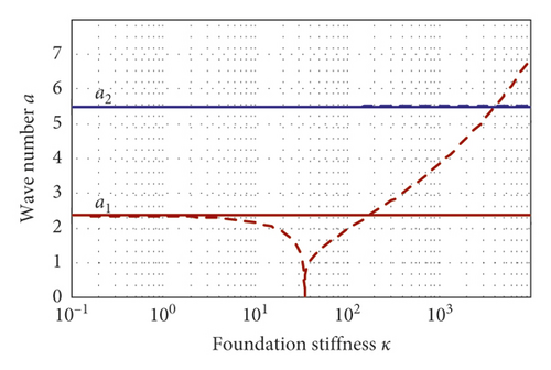
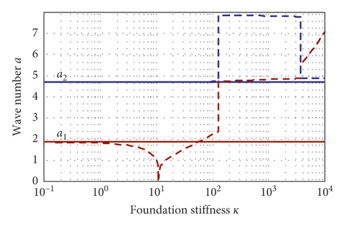
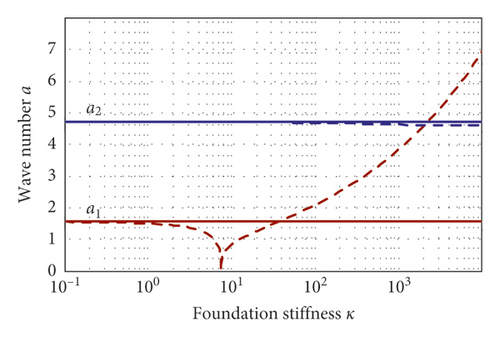
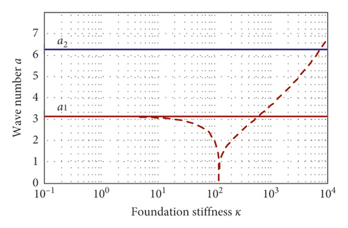
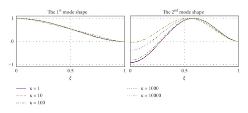
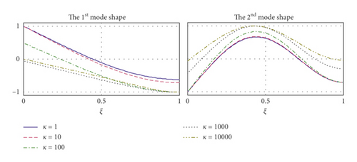
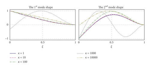
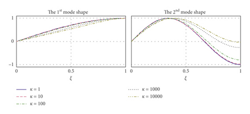
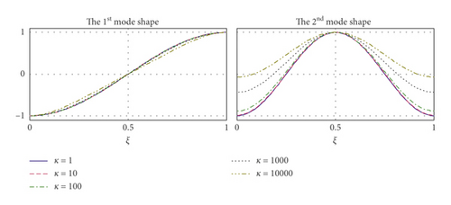
Besides, the influence of the foundation’s movability depends heavily upon the stiffness κ as shown in Figure 4 which shows variations of the first two wave numbers with κ for five degenerated cases with a static foundation and with a movable foundation. One can see that the wave number is independent of κ for the cases of static foundation shown by solid line. However, for the cases of movable foundation, the wave number decreases first slowly and then fast to zero at the point of the critical foundation stiffness κ = κc, and after this point, it rises fast with κ. And, it is interesting to find for the case of Fr-Fi that the first wave number a1 jumps at a point around κ = 125.2 from about 2.3648132 up to about 4.7361473, and the second wave number jumps at the same point from about 4.7361473 up to about 7.8506932, and then, at a point around κ = 3654.4, the first wave number jumps once again from about 4.8728569 up to about 5.4978386 while the second one from about 7.7907950 down to about 4.8728576. The fact is the original first mode vanishes when κ crosses 125.2, so the original second mode becomes the first one and the original third one becomes the second one, while when κ > 3654.4, the first mode reappear, so the second mode resets, just as shown in Figure 5(c). Figure 5 shows variations of first two mode shapes with κ for five degenerate cases. Generally, the influence of κ is larger on the second mode shape than on the first one. As κ increases, the mode shapes approach a straight line, which accords with the physical truth that when the foundation is rigid the beam cannot deform, i.e., keeping the shape of a straight line.
4.3. Effects of the Movable Foundation on Elastically Restrained Beams
-
Case 1: κ3 = κ4 = 0 and κ1 = κ2 = 1, 10, 100
-
Case 2: κ3 = κ4 = 10 and κ1 = κ2 = 1, 10, 100
-
Case 3: κ1 = κ2 = 0 and κ3 = κ4 = 1, 10, 100 and
-
Case 4: κ1 = κ2 = 10 and κ3 = κ4 = 1, 10, 100
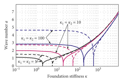
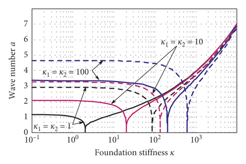
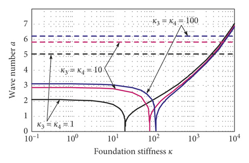
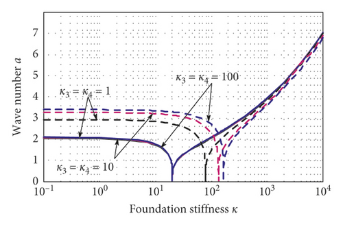
Figure 6 shows variations of the first two wave numbers with the foundation stiffness κ and end restraint stiffness for the above four cases. Clearly, Case 3 is different from others. As shown in Figure 6(c), the influence of κ is like that shown in Figures 4(a), 4(c), and 4(d) for which there exists only one critical foundation stiffness and the second mode is nearly independent of κ. However, for the other three cases, there exists two critical foundation stiffnesses, a smaller one for the first mode and a larger one for the second mode. As κ increases, both wave numbers firstly decrease to zero at the point of their respective critical foundation stiffness and then increase after this point. And, for each of the three cases, wave numbers under different end restraint stiffnesses approach the same as κ increases. Besides, for Case 1 and Case 2, vertical end restraint stiffnesses, κ1 and κ2, have impact on both wave numbers which increase with κ1 and κ2. However, for Case 4, the first wave number is independent of κ3 and κ4 as shown in Figure 6(d).
5. Conclusions
- (i)
A general model governing free vibrations of an elastically restrained Euler beam resting on a movable Winkler foundation was first established.
- (ii)
The frequency equations and corresponding mode shapes were analytically derived and can degenerate into many other classical ones.
- (iii)
If one of the beam ends is not vertically fixed, the effects of the movable foundation cannot be neglected.
- (iv)
Contrast to a beam resting on a static foundation and with the same rigid end conditions, movability of the foundation mainly affects the first two modes and the influence depends upon end restraints. The wave number may be enlarged or reduced for different end restraints.
- (v)
For a rigidly restrained beam resting on a movable Winkler foundation, there exists only one critical foundation stiffness. And, as the foundation stiffness κ increases, the first wave number firstly decreases to zero at the critical foundation stiffness and then increases after this point. The wave number may jump up and down with κ for some case of end condition.
- (vi)
There may be two critical foundation stiffnesses for an elastically restrained beam resting on a movable foundation, a smaller one for the first mode and a larger one the second mode. With κ increasing, the first two wave numbers firstly decrease to zero at their respective critical foundation stiffness and then increase after this point.
Conflicts of Interest
The authors declare that there are no conflicts of interest regarding the publication of this paper.
Acknowledgments
This research was supported by the National Natural Science Foundation of China (Nos. 51508333 and 51708462).
Open Research
Data Availability
The data used to support the findings of this study are included within the article.


