Design and Analysis of CFD Experiments for the Development of Bulk-Flow Model for Staggered Labyrinth Seal
Abstract
Nowadays, bulk-flow models are the most time-efficient approaches to estimate the rotor dynamic coefficients of labyrinth seals. Dealing with the one-control volume bulk-flow model developed by Iwatsubo and improved by Childs, the “leakage correlation” allows the leakage mass-flow rate to be estimated, which directly affects the calculation of the rotor dynamic coefficients. This paper aims at filling the lack of the numerical modelling for staggered labyrinth seals: a one-control volume bulk-flow model has been developed and, furthermore, a new leakage correlation has been defined using CFD analysis. Design and analysis of computer experiments have been performed to investigate the leakage mass-flow rate, static pressure, circumferential velocity, and temperature distribution along the seal cavities. Four design factors have been chosen, which are the geometry, pressure drop, inlet preswirl, and rotor peripheral speed. Finally, dynamic forces, estimated by the bulk-flow model, are compared with experimental measurements available in the literature.
1. Introduction
Labyrinth seals and their sealing principles are commonplace in turbomachinery and they can arise in various configurations [1]. The most popular are the straight-through, the staggered, the slanted, and the stepped labyrinth seals. By their nature, labyrinth seals are noncontact seals that can harmfully rub against stationary parts [2]. Their working principle consists in reducing the leakage mass-flow rate by dissipating the flow kinetic energy via sequential cavities arranged to impose a tortuous path to the fluid (see the scheme of a staggered labyrinth seal in Figure 1). The speed and pressure at which they operate are bounded by their structural design.
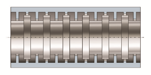
The clearance is defined by aerothermomechanical conditions that stave off the contact against the shroud under radial and axial excursions. In straight-through labyrinth seal, the angle at which the flow approaches to the teeth is usually 90°; the coefficients of discharge (Cf), peculiar of labyrinth seals, emphasize the effectiveness of the sealing element. The discharge coefficient is defined as the ratio between the actual mass-flow rate and that in ideal flow conditions. The relation between the sharpness of the tooth and the ability to restrict the flow has been given by Mahler [3] and more recently explored by means of computational fluid dynamics (CFD) in [4].
Labyrinth seals are effective in reducing the flow but have a strong effect on the dynamic behaviour and often lead to dynamic instabilities. These problems have been addressed by several researchers starting with Thomas [5] and Alford [6]. They recognized that dynamic forces can lead to instabilities. Childs [7] addressed the root cause to the swirl velocity and introduced the swirl brake at the seal inlet to mitigate the circumferential velocity of the fluid.
The current trends in the oil and gas market lead the manufacturers to maximize the turbomachinery efficiency. This target pushes the rotor dynamic design to be challenging. Therefore, the accuracy of rotor dynamic analyses has become of primary importance to avoid undesired instability phenomenon. Because labyrinth seals are one of the major sources of destabilizing effects, it is straightforward that the accurate prediction of labyrinth seal dynamic coefficients is crucial.
The bulk-flow model is the most used approach for estimating the seal dynamic coefficients thanks to the low computational effort compared to CFD calculations. It was developed by Iwatsubo [8] and improved by Childs and Scharrer [9] in the 80s. The bulk-flow model is a control volume approach: the continuity and circumferential momentum equations are solved for each cavity, allowing the circumferential fluid dynamics within the seal to be investigated. For the axial fluid dynamics, empirical correlations are required, aiming at estimating the leakage and the pressure distribution. No turbulence model is employed in the bulk-flow model; therefore also the effect of the turbulence is demanded to correlations that estimate the wall shear stresses. The leakage strictly influences the swirl velocity profile along the seal and consequently the resulting dynamic coefficients.
Dealing with staggered labyrinth seals, few models allow the dynamic coefficients to be estimated, despite the fact that this seal configuration is widely used in turbomachinery, especially in steam turbines. The advantage of this configuration, with respect to straight-through labyrinth seal, is the reduction of the leakage mass-flow rate given equal clearance.
Wang et al. [10] use the straight-through bulk-flow model for the staggered labyrinth seal; Childs [7] considered the kinetic energy carry-over equal to the unity for all the cavities. Kwanka and Ortinger [11] compared the numerical results of the bulk-flow theory with experimental results performed on a staggered labyrinth seal. They revealed the strong connection between the circumferential flow and the axial one. The numerical results were not accurate compared to the experimental ones. The leakage correlation used by Kwanka et al. did not reproduce well the “zig-zag” behaviour of the discharge coefficients, because they considered an average value. Li et al. [12] investigated numerically and experimentally the effects of the pressure ratio and rotational speed on the leakage flow in a staggered labyrinth seal. In their paper, the authors do not report any correlation for the prediction of the leakage flow.
This paper aims at filling the lack of analytical models for staggered labyrinth seals. Firstly, the authors performed a design and analysis of computer experiments (DACE) using steady-state CFD analysis to develop a new empirical correlation for the prediction of staggered labyrinth seal leakage. The CFD analysis investigates several seal geometries and various operating conditions, which are pressure drop, inlet preswirl, and rotor peripheral speed. To capture the nonlinear dependency of these factors on the flow conditions, three levels each are chosen, except two for the preswirl. The correlation obtained is finally verified numerically, comparing the results of the bulk-flow model with those of a CFD analysis in terms of leakage mass-flow rate, pressure distributions, and Mach number.
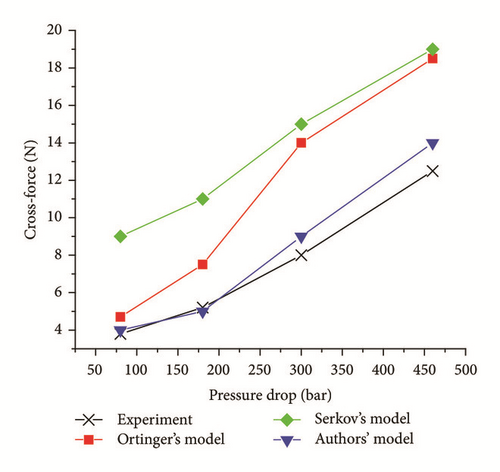
In conclusion, the rotor dynamic coefficients prediction has been compared with the experimental measurements performed by Kwanka and Ortinger [11], highlighting the more accurate estimation of the cross-force with respect to other bulk-flow models.
2. Bulk-Flow Steady-State Solution
The estimation of the steady leakage, pressure, and circumferential velocity distribution represents the so-called zeroth-order solution in the bulk-flow model, as described in [13]. For a fixed pressure drop and assuming, at a first stage, an isenthalpic process, the leakage and the pressure distribution in the seal cavities are determined by solving iteratively the continuity equation, until the mass-flow rate is equal for each control volume (see Figure 2). Then, the enthalpy and the circumferential velocity in each cavity are determined by solving the coupled circumferential momentum and energy equation. Multivariate Newton-Raphson algorithm is employed to find the solution. At the following step, the leakage is calculated one more time, considering the enthalpy variation previously estimated. The iteration continues until the leakage mass flow-rate converges.

The continuity, circumferential momentum, and energy zeroth-order equations for each cavity are stated as follows:
3. Preliminary Results
To investigate the accuracy of the leakage correlation used for straight-through labyrinth seals in the case of staggered seals, the zeroth-order solutions are compared with the CFD results. Steady-state CFD analysis is very accurate in the prediction of the leakage, static pressure, and circumferential velocity within the seal; therefore CFD has been considered as the reference for the zeroth-order solution.
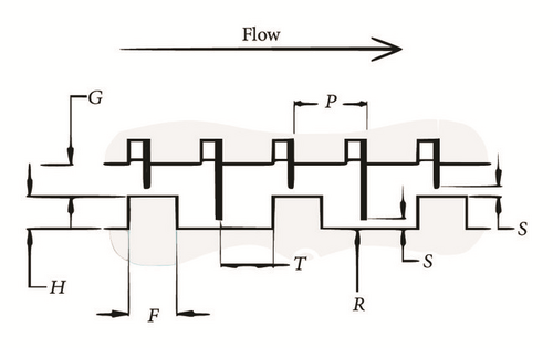
A detailed description of the CFD analysis is shown in the next chapter of the paper. The seal geometry is shown in Figure 3, and the geometrical parameters are reported in Table 1, using the nomenclature shown in Figure 4. The working fluid is the steam.
| Seal geometry | |
|---|---|
| Shaft radius Rs | 189 |
| Radial clearance (mm) s | 0.6 |
| Steps-to-casing radial distance (mm) G | 2.00 |
| Steps height (mm) H | 2.00 |
| Steps width (mm) F | 3.00 |
| J-strips width at tip (mm) W | 0.25 |
| J-strips pitch (mm) P | 4.00 |
| J-strip-to-step axial distance (mm) T | 2.75 |
| J-strips number NJ | 47 |
| Rotor steps number NS | 24 |

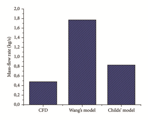
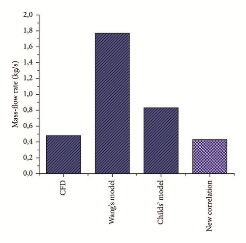
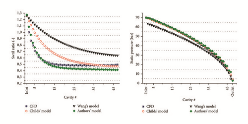
The results in terms of leakage mass-flow rate are shown in Figure 5, while the swirl velocity and the pressure distribution are shown in Figure 6. The mass-flow rate is overestimated for both bulk-flow models: the relative error is, respectively, equal to +75% and +272% for Childs’ model and Wang’s model. The swirl ratios along the seal cavities are strongly influenced by the mass flow. Even if the asymptotic value of the swirl ratio for Childs’ model is equal to that of the CFD, the values in the first cavities are far from the CFD ones. The predicted static pressure distribution is very similar to Childs’ model.
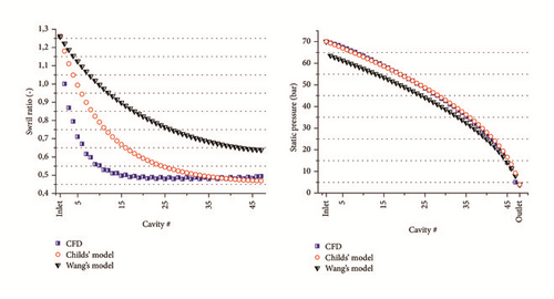
Eventually, Childs’ model is the more accurate one-control volume bulk-flow model in the literature for staggered labyrinth seals; however, the results in terms of leakage, pressure, and circumferential velocity distribution are not accurate enough compared to CFD results. The zeroth-order solution strongly influences the prediction of the seal dynamic coefficients; hence, the authors decide to develop a new empirical correlation for staggered labyrinth seal.
4. Design and Analysis of Computer Experiments
Design and analysis of CFD experiments allow several staggered seal geometries and operating conditions to be investigated for the development of a new leakage correlation. A priori, it is not possible to know which are the geometric parameters that influence the leakage flow rate, as well as the operating conditions.
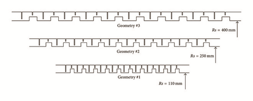
Three seal geometries are chosen according to the OEMs design criteria, while additional two are selected in order to extend the domain of the investigation in the case of possible axial shifting of the rotor. Axial excursion of the rotor commonly happens during the start-up condition or even during the variation of the process parameters (i.e., the output power density). The validation of the correlation also for off-design seal operations allows extending the seal dynamic coefficients predictability. The geometric parameters that define the seal geometry are those reported in Table 1. Three different rotor diameters have been investigated (220 mm, 500 mm, and 800 mm); the teeth are 20, while the rotor steps are 10. The additional two seal geometries are equal to those with the rotor diameter equal to 500 mm (geometry #4) and 800 mm (geometry #5) but with a different length of the rotor step. The three main geometries are shown in Figure 7; the steam flows from right to left.
Because CFD analysis is very time-consuming, a factorial DACE is performed, even if not all the combinations of the parameters have been investigated. The list of the CFD analysis performed is shown in Table 2.
| Test | Pressure drop | Geometry | Peripheral speed | Preswirl |
|---|---|---|---|---|
| (bar) | (m/s) | — | ||
| 1 | 50 | Geom 1 | 69.1 | 1.9 |
| 2 | 20 | Geom 1 | 69.1 | 1.9 |
| 3 | 10 | Geom 1 | 69.1 | 1.9 |
| 4 | 50 | Geom 2 | 69.1 | 1.9 |
| 5 | 50 | Geom 3 | 69.1 | 1.9 |
| 6 | 20 | Geom 2 | 69.1 | 1.9 |
| 7 | 20 | Geom 3 | 69.1 | 1.9 |
| 8 | 50 | Geom 4 | 69.1 | 1.9 |
| 9 | 50 | Geom 5 | 69.1 | 1.9 |
| 10 | 50 | Geom 1 | 69.1 | 0.5 |
| 11 | 20 | Geom 1 | 69.1 | 0.5 |
| 12 | 50 | Geom 2 | 69.1 | 0.5 |
| 13 | 50 | Geom 3 | 69.1 | 0.5 |
| 14 | 50 | Geom 1 | 115.2 | 1.9 |
| 15 | 20 | Geom 1 | 115.2 | 1.9 |
| 16 | 50 | Geom 2 | 115.2 | 1.9 |
| 17 | 50 | Geom 1 | 161.3 | 1.9 |
| 18 | 50 | Geom 1 | 115.2 | 0.5 |
| 19 | 20 | Geom 2 | 115.2 | 1.9 |
| 20 | 50 | Geom 2 | 115.2 | 0.5 |
| 21 | 50 | Geom 3 | 115.2 | 0.5 |
| 22 | 20 | Geom 2 | 69,1 | 0,5 |
| 23 | 20 | Geom 3 | 69.1 | 0.5 |
| 24 | 20 | Geom 1 | 115.2 | 0.5 |
| 25 | 50 | Geom 4 | 161.3 | 1.9 |
| 26 | 50 | Geom 5 | 161.3 | 1.9 |
| 27 | 10 | Geom 4 | 69.1 | 1.9 |
| 28 | 10 | Geom 5 | 69.1 | 1.9 |
| 29 | 50 | Geom 4 | 69.1 | 0.5 |
| 30 | 50 | Geom 5 | 69.1 | 0.5 |
| 31 | 50 | Geom 1 | 161.3 | 0.5 |
| 32 | 10 | Geom 1 | 69.1 | 0.5 |
| 33 | 10 | Geom 1 | 161.3 | 1.9 |
5. CFD Analysis and Results
The domain discretization has been carried out using Ansys™ [22]. The meshing procedure consists of creating, at a first stage, the 2D computational domain by means of quadrilateral element. After that, the 2D domain is rotated circumferentially to obtain the 3D structured mesh, composed by hexahedra elements. The 3D domain corresponds to a five-degree sector along the circumferential direction. For instance, in the case of the seal geometry with the diameter equal to 220 mm, one element per degree has been used for the mesh rotation, while for the other diameters, two elements per degree are necessary to avoid excessive stretched elements in the circumferential direction.
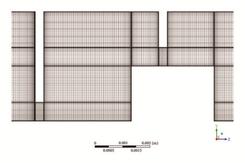
It is worth mentioning that the discretization has been refined close to the wall to achieve a low Reynolds approach in the boundary layer (see Figure 8). Details concerning the discretization have been summarized in Table 3.
| Mesh parameters | |
|---|---|
| Height of first layer | 1 · 10−3 mm |
| Cell expansion ratio | 1.2 |
| Number of elements | 1.25 million (∅ 220 mm) |
| 2.50 million (∅ 500 and 800 mm) | |
Among the several approaches to solve numerically the Navier-Stokes equations, the most employed in the turbomachinery field is the Reynolds Averaged Navier-Stokes (RANS) due to the good compromise between accuracy and computational time required. The IAWPS steam tables have been employed to properly model the fluid properties [23].
Turbulence has been modelled using the SSTk-ω model, firstly introduced by Menter [24] and widely tested in turbomachinery application in the last decade. This turbulence model is associated with the automatic near wall treatment, where a smooth transition between the low Reynolds number approach and the standard wall functions is adopted. However, due to the low value of y+ achieved, using the grids employed in this paper, this treatment corresponds to the low Reynolds model; hence, the viscous sublayer is not modelled but directly solved. This approach is surely preferable due to the final purpose of the present analysis, where the exact amount of flow rate for a given pressure drop must be assessed through the clearances.
The boundary condition scheme is hereafter introduced in Figure 9. The same set of conditions are imposed to all the test cases. The value of inlet total pressure is changed at each new iteration to target the desired pressure drop; moreover, the circumferential velocity component is adjusted to obtain the desired preswirl ratio.

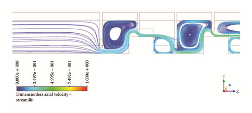
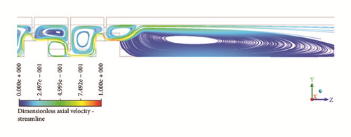
The results of some simulations are shown in Figures 10 and 11. Static pressure and temperature contours are reported in Figure 10. Dimensionless values are obtained using the downstream value equaling the unity. Furthermore, streamlines in the meridional plane are illustrated in Figure 11, focusing on the inlet and outlet locations. The flow structure before the first clearance is different from the one occurring upstream the consecutive teeth.


6. Discharge Coefficients Correlation
Since the mass-flow rate, pressure, and density can be evaluated by the CFD, the discharge coefficient for each cavity can be evaluated. Using the CFD data of all the tests investigated by the DACE, the idea is to develop a new correlation based on the geometric parameters and on the operating conditions.
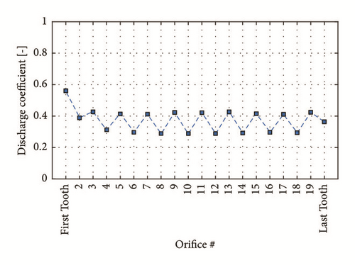
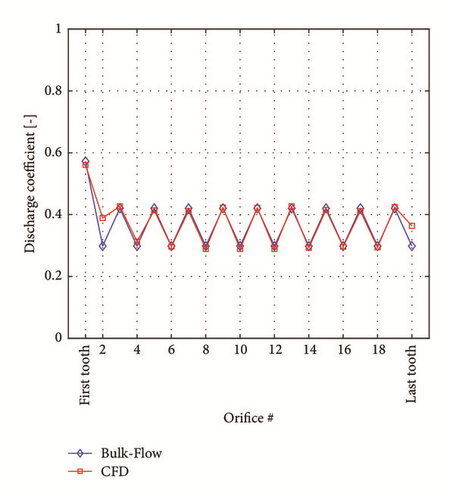
The authors have observed that the discharge coefficients have different values depending on the constriction type (long teeth or short teeth coupled with the rotor step); however, the values along the seal orifices almost remain constant, for both the constriction types, expect for the first tooth (see Figure 12). Since the discharge coefficient depends on the angle at which the fluid approaches to the tooth, the different discharge coefficient is likely due to the fluid, which approaches to the long teeth and to the short ones in two different manners. For instance, as can be observed in Figure 12, for test 1 shown in Table 2, the discharge coefficient in correspondence of the short teeth is about 0.3, whereas for long teeth it is practically constant and equal to 0.48. For the first tooth, the discharge coefficient is about 0.6.
After several investigations, the authors have observed that two geometrical parameters mainly influence the discharge coefficient. These parameters are listed in Table 4. The parameter s/(H + G) is related to the ratio between the height of the constriction and the height of the seal. The other parameters are related to the axial position and length of the rotor step. In addition, one parameter regarding the operating conditions has been considered. From a primary screening of the CFD results, the authors observed that the only operating condition parameter that significantly affects the leakage is the pressure drop. The inlet preswirl and the rotor peripherical speed have practically no influence on the mass flow and therefore on the pressure distribution.
| Geometric parameters for the j-strip | Geometric parameters for the rotor step |
|---|---|
For confidentiality reasons, the values of the coefficients q0, …, q6 and p0, …, p6, shown in (12)–(15), are not reported in the paper.
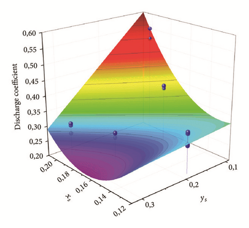
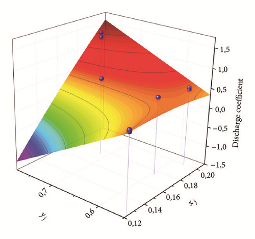
Figures 13 and 14 show the polynomial surface that fits the discharge coefficients evaluated with the CFD analysis for both short teeth (Figure 13) and long teeth (Figure 14). The blue points represent the average value of the discharge coefficients, in correspondence of the rotor step, for each CFD analysis. The CFD points are well fitted, since the adjusted R2 [26] is about 0.97 for the short teeth and 0.98 for the long ones, whereas the root mean square error (RMSE) [26] is equal to 0.01406 and 0.01399, respectively. These statistical parameters highlight the goodness of fit of the data.
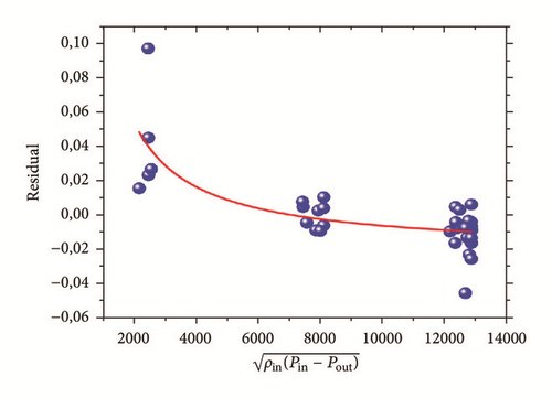
Furthermore, Figures 15 and 16 show the fitting of the residual by the operating parameter (). The blue points represent the average value of the residual, in correspondence of the rotor step, for each CFD analysis. The adjusted R2 is about 0.9689 and the RMSE is 0.01406.
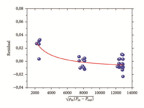
The discharge coefficient in correspondence of the first tooth has been considered constant for all the tests and it seems to be uncorrelated from the geometric parameters and from the pressure drop.
6.1. Prediction of the Leakage and Pressure Distribution
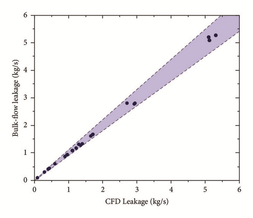
The new discharge coefficient correlation has been implemented in the bulk-flow model. The bulk-flow leakage mass-flow estimations compared to the CFD leakage are shown in Figure 17. The bulk-flow leakage is in the range of ±6% of relative error (the blue region defines the ±10% of relative error).
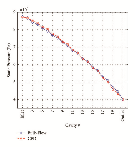
Moreover, the pressure distribution predicted with the bulk-flow model is very similar to that evaluated with the CFD. In Figure 18(a), the pressure shows a “zig-zag” behaviour along the seal, which is due to the nonconstant discharge coefficients (see Figure 18(b)).
6.2. Prediction of the Circumferential Velocity
In this section, the authors have compared the fluid-wall shear stresses estimated by the bulk-flow model with those computed using the CFD. For the sake of brevity, only the results related to test case 1 are reported (see Figure 19) considering both cases with and without the axial velocity component in the bulk-flow model. The accuracy of the results is still long valid for the other tests.
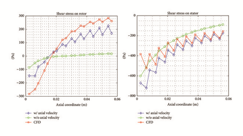
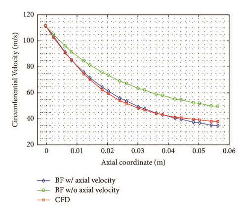
The CFD shear stresses are averaged along the length of each cavity to be compared with the bulk-flow results. In Figure 20, the circumferential velocity profile is shown. Typically, in the 1CV bulk-flow model (see bulk-flow models in [9, 10, 18]), the shear stresses are evaluated considering only the circumferential velocity, whereas the authors have considered also the contribution of the axial velocity (see (7)) as suggested in [19].
6.3. Numerical Verification of the New Correlation
The new correlation has been numerically verified using the results of the staggered seal shown in Figure 3, which has about twice the teeth of the DACE seal geometries and moreover the operating conditions are far from those investigated in the DACE. The relative error between the leakage evaluated with the bulk-flow model and the one with the CFD is equal to 10% (see Figure 21). Moreover, the pressure distribution is accurately reproduced, and the sonic flow condition is reached as in the CFD analysis (see Figure 23). The results of Childs’ model and Wang’s model are reported in Figures 21 and 22.

7. Prediction of Staggered Labyrinth Seal Rotor Dynamic Coefficients
7.1. Bulk-Flow First-Order Mathematical Treatment
The bulk-flow model, developed by the authors, is based on the one-control volume bulk-flow model described in [13, 27–29] and here customized for staggered labyrinth seal. Each cavity of the seal is modelled by one-control volume. The model includes the steam properties evaluated with the IAPWS tables [23]. The model is based on the perturbation analysis, as described in [7].
7.2. Perturbation Analysis
7.3. Dynamic Coefficients
7.4. Numerical Results
A preliminary investigation on the dynamic behaviour of staggered labyrinth seals has been performed in the paper. The numerical results are compared with the experimental measurements performed by Kwanka and Ortinger in [11]. The radial force generated by a fourteen-cavity staggered labyrinth seal was obtained by integrating the pressure measured along the circumferential direction. The maximum circumferential velocity at the seal inlet is equal to 22 m/s. The seal geometry and the operating conditions are reported in Tables 5 and 6.
| Shaft radius | Rs | 111 | [mm] |
| Radial clearance | s | 0.50 | [mm] |
| Steps-to-casing radial distance | G | 4.00 | [mm] |
| Steps height | H | 5.00 | [mm] |
| Steps width | F | 10.50 | [mm] |
| J-strips width at tip | W | 0.30 | [mm] |
| J-strips pitch | P | 10.50 | [mm] |
| J-strip-to-step axial distance | T | 5.00 | [mm] |
| J-strips number | NJ | 15 | |
| Rotor steps number | NS | 8 |
| Pressure drop | ΔP | 0.8 | [bar] |
| 1.80 | [bar] | ||
| 3.00 | [bar] | ||
| 4.60 | [bar] | ||
| Outlet pressure | Pout | 1.01 | [bar] |
| Inlet temperature | Tin | 693 | [K] |
| Rotational speed | Ω | 3000 | [rpm] |
Figure 24 shows the measured cross-force as a function of the pressure drop, considering the rotor eccentricity equal to 0.4 mm. The geometry of the seal and the operating condition are far from those used for the development of the leakage correlation, but the prediction obtained by the authors’ model is more accurate than the numerical results reported in the paper by Kwanka and Ortinger.
8. Conclusion
The paper focuses on the numerical modelling of staggered labyrinth seals to predict the rotor dynamic coefficients. By considering the one-control volume bulk-flow model, a new leakage correlation has been developed to estimate accurately the zeroth-order solution: leakage mass-flow rate, static pressure distribution, circumferential velocity distribution, and temperatures.
Design and analysis of CFD experiments have been used to develop the leakage correlation using four design factors: the geometry, the pressure drop, the inlet preswirl, and the rotor peripherical speed. Only the geometry and the pressure drop have been confirmed to be effective on the estimation of the leakage and static pressure.
The procedure used by the authors for the development of the correlation relies on the definition of the discharge coefficient. The discharge coefficients have different values in correspondence of the long teeth with respect to the short ones. Polynomial functions have been used to calculate the discharge coefficients as a function of the seal geometry parameters and of the pressure drop. Once these coefficients have been evaluated, the static pressure in the cavities is estimated till the leakage converges.
Finally, a detailed description of the one-control volume bulk-flow model for staggered labyrinth seals has been reported in the paper. The model allows the rotor dynamic coefficients to be estimated. Numerical results are compared to experimental measurements by Kwanka and Ortinger. The results of the model developed by the authors are more accurate than the other numerical models.
Nomenclature
-
- ari, asi:
-
- Dimensionless length of the rotor and stator of the ith cavity
-
- Ai, A0i:
-
- Unsteady and steady cross-sectional area of the ith cavity
-
- Cfi:
-
- Discharge coefficient under the ith tooth
-
- C:
-
- Direct damping coefficient of the seal
-
- c:
-
- Cross-coupled damping coefficient of the seal
-
- Dhi, Dh0i:
-
- Unsteady and steady hydraulic diameter of the ith cavity
-
- er, es:
-
- Absolute roughness of the rotor and stator surface
-
- F:
-
- Steps width
-
- Fx, Fy:
-
- Lateral forces acting on the rotor
-
- fri, fsi:
-
- Friction factors on the rotor and stator surfaces
-
- G:
-
- Step-to-casing radial distance
-
- H:
-
- Steps height
-
- hi, h0i:
-
- Unsteady and steady enthalpy of the ith cavity
-
- :
-
- Unsteady and perturbed clearance
-
- K:
-
- Direct stiffness coefficient of the seal
-
- k:
-
- Cross-coupled stiffness coefficient of the seal
-
- P:
-
- Length of the ith cavity
-
- :
-
- Unsteady and steady mass flow rate in the ith orifice
-
- NJ:
-
- Number of long teeth
-
- NS:
-
- Number of rotor steps
-
- Pi, P0i:
-
- Unsteady and steady pressure in the ith cavity
-
- Pin:
-
- Seal inlet pressure
-
- Pout:
-
- Seal outlet pressure
-
- p0, p1, … , p6:
-
- Polynomial coefficients for the discharge coefficients in correspondence of the short teeth combined with the rotor step
-
- q0, q1, … , q6:
-
- Polynomial coefficients for the discharge coefficients in correspondence of the long teeth
-
- r0:
-
- Radius of the circular orbit of the rotor
-
- Rs:
-
- Rotor radius
-
- Rsi, Rs0i:
-
- Rotor radius in the tooth location and rotor base radius
-
- si:
-
- Clearance of the ith cavity
-
- T:
-
- Long tooth-to-step axial distance
-
- Ui:
-
- Axial velocity of the ith cavity
-
- Vi, V0i:
-
- Unsteady and steady tangential velocity in the ith cavity
-
- x(t), y(t):
-
- Rotor displacement in the lateral directions
-
- xj, yj:
-
- Geometrical parameters for the j-strip
-
- xs, ys:
-
- Geometrical parameters for the short teeth and rotor steps
-
- W:
-
- Tooth width
-
- ϵ:
-
- Perturbation parameter
-
- ρi, ρ0i:
-
- Unsteady and steady density in the ith cavity
-
- τri, τr0i:
-
- Unsteady and steady rotor shear stress in the ith cavity
-
- τsi, τs0i:
-
- Unsteady and steady stator shear stress in the ith cavity
-
- μi:
-
- Kinetic energy carry-over coefficient in the ith cavity
-
- νi:
-
- Kinetic viscosity in the ith cavity
-
- ω:
-
- Whirling speed of the orbit of the rotor
-
- Ω:
-
- Rotational speed of the rotor
-
- j:
-
- Imaginary part.
Abbreviations
-
- CFD:
-
- Computational fluid dynamics
-
- DACE:
-
- Design and analysis of computer experiments
-
- OEMs:
-
- Original equipment manufacturers
-
- SST:
-
- Shear stress transport.
Conflicts of Interest
The authors declare that they have no conflicts of interest.


