An Integral Formulation of Two-Parameter Fatigue Crack Growth Model
Abstract
A two-parameter fatigue crack growth algorithm in integral form is proposed, which can describe the continuous crack growth process over the time period. In this model, the fatigue crack propagation behavior is governed by the temporal crack-tip state including the current applied load and the physical condition due to the previous load sequence. The plasticity-induced crack closure, left by the historical loading sequence, controls the following fatigue crack growth behavior and typically leads to the interaction effects. In the proposed method, a modified crack closure model deriving from the local plastic deformation is employed to account for this load memory effect. In general, this model can simulate the fatigue crack growth under variable amplitude loading. Additionally, this model is established on the physical state of crack tip in the small spatial and temporal scale, and it is used to evaluate the macroscopic crack propagation and fatigue life under irregular tension-tension loading. A special superimposed loading case is discussed to demonstrate the advantage of the proposed model, while the traditional two-parameter approach is not proper functional. Moreover, the typical various load spectra are also employed to validate the method. Good agreements are observed.
1. Introduction
Since the damage tolerance concept is of great significance to the engineering design, the prediction of fatigue crack growth life under the service environment becomes a prerequisite. Many fatigue-critical structures are usually subjected to variable amplitude (VA) loading condition. The fatigue analysis in this case has to encounter high nonlinear mechanisms of damage accumulation. An appropriate solution to the interaction effects in crack propagation process under VA loading is necessary and valuable.
Many references have focused to evaluate the interaction effects and further predict the fatigue crack growth under complex loading condition [1–4]. Wheeler and Willenborg et al. state that the yield zone size correlates with the fatigue crack growth rate [5, 6]. Afterwards, the forward and reverse plastic zone interaction is considered to be an essential characteristic of load sequence effects [7, 8]. Based on this hypothesis, Zhang et al. introduced a novel parameter, da/dS, to define the fatigue crack propagation rate with the stress variation at any moment of a cycle [7]. Furthermore, Zhang derived the relationship between da/dS and the traditional da/dN parameter that represented the fatigue crack growth rate per cycle. Lu and Liu proposed a small time scale fatigue crack growth model, in which the incremental crack growth kinetics was calculated [8]. Zhang and Liu stated that the crack-tip opening displacement (CTOD) is the driving parameter of fatigue crack growth and developed a time-based formulation [9]. Nevertheless, the computation results in the internal of a cycle are discontinuous by using these aforementioned methods. The requirement of cycle counting before predicting the fatigue crack growth is inevitable, which leads to the fundamental incapacity to utilize the load sequence information. Sadananda and Vasudevan suggested that the fatigue crack propagation rate is determined by two parameters, the maximum stress intensity factor, Kmax, and the stress intensity factor range, ΔK [10]. Therefore, this paper presents a novel integral formulation of two-parameter model to calculate the continuous fatigue crack propagation process without cycle counting. An equivalent physical state is proposed. It is assumed that the various physical states can be quantized by the several mechanism parameters. This hypothesis is beneficial to characterize the previous loading effects through the measurable physical function. Hence, the fatigue crack growth behavior is simultaneously determined by the current applied loads and the physical state ahead of the crack tip. In this investigation, the driving parameters are designated to be the current loading and the CTOD variation which is under the influence of the plastic-induced crack closure. Based on that, an integral two-parameter fatigue crack growth model is derived in the small spatial and temporal scale. The macroscopic crack propagation behavior under irregular tension-tension loading condition at arbitrary time can be estimated.
The paper is organized in four sections. Firstly, the model in integral form is proposed to calculate the fatigue crack growth rate. Next, the modified crack closure model is reviewed. Especially, the superimposed loading condition is discussed. In addition, Section 3 validates this model by comparison with the experimental data of aluminum alloy under VA loading. Finally, Section 4 summarizes and concludes this investigation.
2. Methodology
2.1. The Integral Fatigue Crack Growth Model
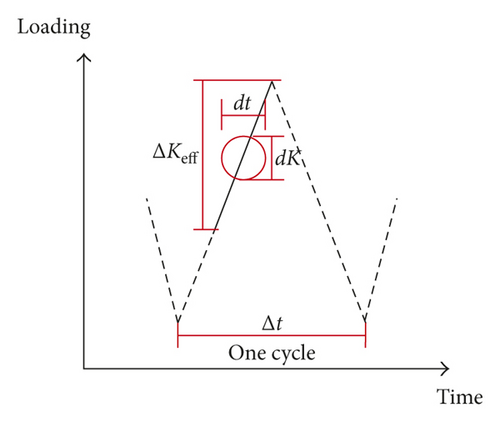
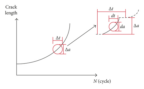
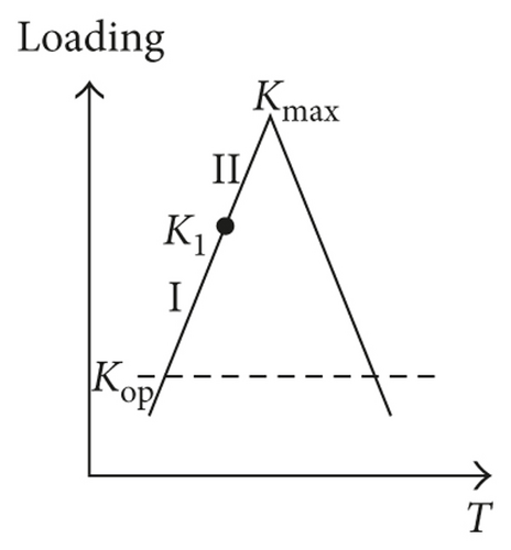
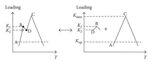
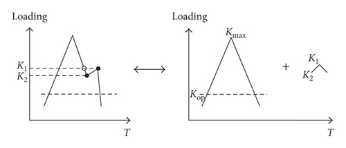
The simplified loading cases are shown in Figure 2. Firstly, the constant amplitude (CA) loading condition is discussed. K1 is the intermediate stage in the loading process. The comparison between the integral model and the traditional two-parameter method is carried out. The crack increments in these two stages can be calculated, as shown in Table 1.
| The integral model | The traditional two-parameter model |
|---|---|
For both of these two models, if the load level directly increases from Kop to Kmax, the crack growth rates during this cycle can be calculated as shown in Table 2.
| The integral model | The traditional two-parameter model |
|---|---|
Especially, when K2 is infinitely approaching to K1, the crack increment will approximate to that in the CA load cycle. It is manifested that the proposed model can handle the continuous crack growth prediction under the complex loads without cycle counting.
2.2. The Analytical Crack Closure Model
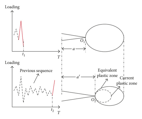
In [12], an analytical crack closure model is developed and verified under CA loading. This model is modified in this paper, and the schematic illustration is shown in Figure 4. The plastic state after the unloading process is shown in the upper plot of Figure 4. There is a reverse plastic zone with dr in diameter ahead of the crack tip “O.” The crack equably closes with length “b.” It is assumed that the crack “annealing” happens once it is fully closed. Therefore, the crack length can be perceived as a − b, and the reverse plastic zone diameter is Dr. The equation Dr = b + dr can be established. In the next loading process, the closed part of crack gradually opens until completes. Eventually, the forward plastic zone is df in diameter. The aforementioned equation can be written as df = Dr − dr.

3. Model Validation
3.1. Model Validation under Superimposed Loading Condition
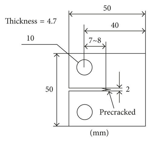
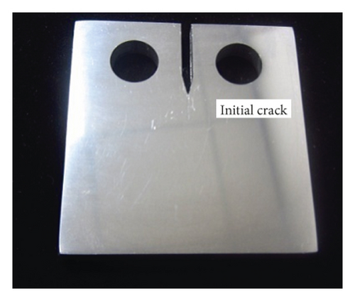
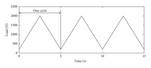
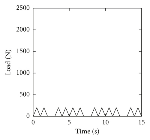

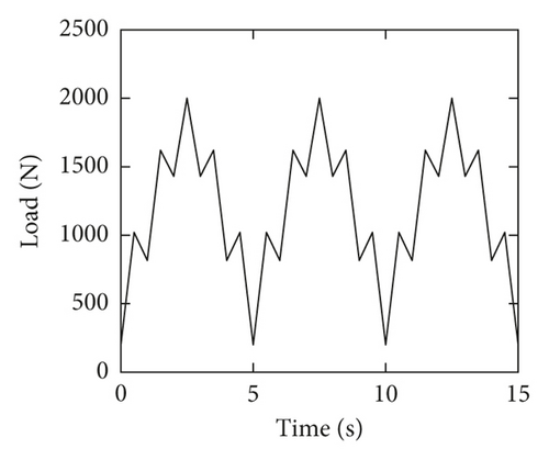
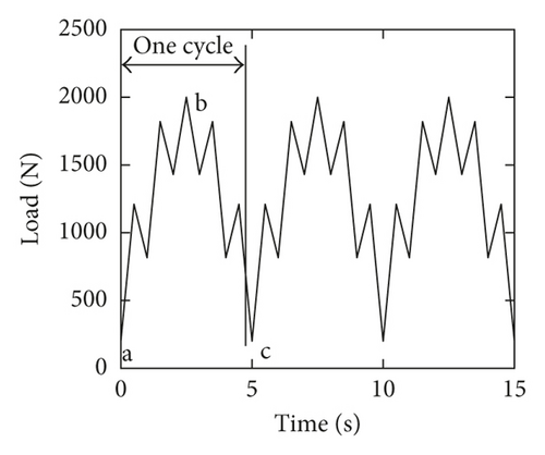
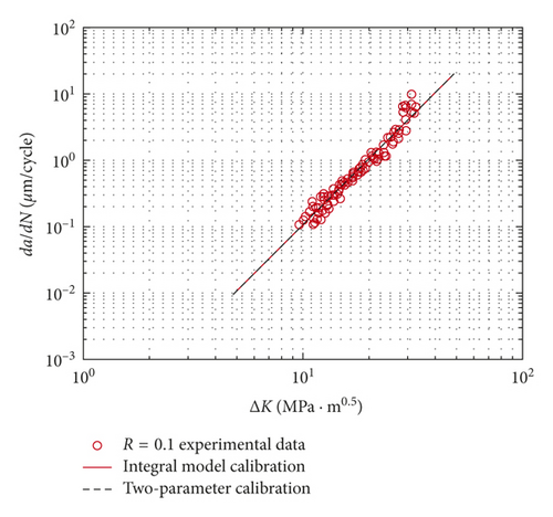
There are several unknown parameters in the fatigue crack growth formulation (6) and (8). The da/dN-ΔK testing data under baseline loading are employed to identify these calibration parameters [9], as shown in Figure 7. The calibration curves of these two models are coincident. The results are CI = 1.3469e − 10, α = 1.3268, and γ = 0.95 for the integral model, and CT = 4.5832e − 11 and mT = 3.3268 for the two-parameter method.
Taking the high ratio loading condition (Figure 6(e)) as an example, the comparison between the integral model and the two-parameter method is shown in Table 3.
| The loading path | The integral model | The traditional two-parameter model |
|---|---|---|
 |
The comparison between the proposed model and the traditional method is also shown in Figure 8. Under the baseline condition, the predicted a-N curves of these two models coincide with each other. The reason is that the integral model is equivalent to the two-parameter method under constant amplitude loading. Nevertheless, in the superimposed loading cases, the predictions of the traditional approach are slower than the baseline results, which is inconsistent with the experiment observation. It is noted that the integral approach can give the better predictions. The proposed model is verified to be appropriate under the superimposed loading condition. It is clear that the interaction effects can be evaluated well.
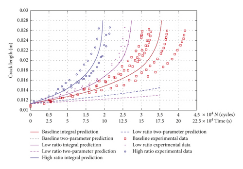
It is natural that the crack-tip damage occurs because of the current loading and the loading history and does not depend upon future loading, in the cycle-counting algorithm [19]. In these cases, as shown in Figure 6(e), when the applied load reaches to the point b, the large cycle cannot be identified without the future loading (point c). Hence, the traditional two-parameter approach is unable to calculate the fatigue crack growth under superimposed loading conditions, whereas the integral model is functional.
3.2. Model Validation under Variable Amplitude Loading
McMillan and Pelloux collected the fatigue testing data on the Al 2024-T3 specimen with center through crack under complex VA loading [20]. The specimens geometry parameters are as follows: width = 229 mm, length = 610 mm, and thickness = 4.1 mm. Two types of spectrum are discussed in this section. Two kinds of the Al 2024-T3 composition are used, and the materials mechanism properties are ultimate strength σult = 473.3 MPa and yield strength σy = 327.9 MPa.
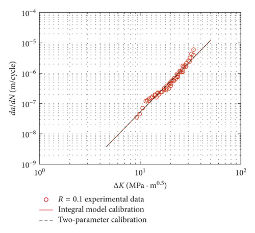
One set of da/dN-ΔK testing data under CA loading (R = 0.1) are employed to calibrate the fitting parameters, as shown in Figure 9 [21]. The calibration results are CI = 6.6619e − 11, α = 1.3874, and γ = 0.9 for the integral model, and CT = 2.1283e − 11 and mT = 3.3874 for the two-parameter model. Good agreements are observed, which proved that the calibration results are available.
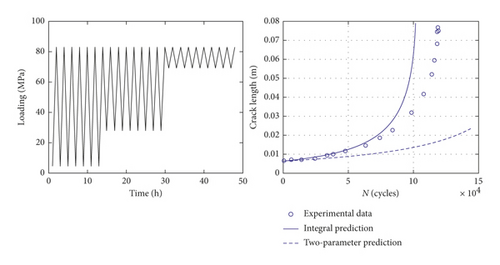
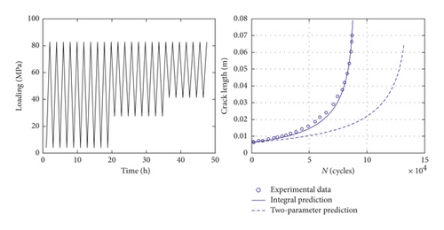
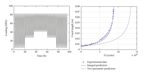
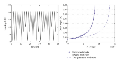
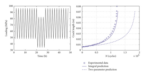
For the constant loading condition, the integral model is equivalent to the two-parameter method, so the predictions of these two approaches are the same. In this section, six types of VA loading condition are used to further validate the proposed model. These spectra and the corresponding prediction results are shown in Figure 10. Taking spectrum 1 as an example, the comparison between the integral model and the two-parameter method is shown in Table 4. For the variable loading case, the calculation results between these two models are obviously different. As it is shown in Figure 10, there is little difference between the first two spectra (spectrum 1 and 2). The reason might be that the crack closure level is stable and almost the same. Thus, the interaction effects under these two cases have no obvious difference, and the predicted a-N curves approximately coincide with each other. It is indicated that the proposed model is able to depict the interaction effects well and give the better predictions than the two-parameter method. In general, the results of the proposed model can match the testing data better.

| The loading path | The integral model | The traditional two-parameter model |
|---|---|---|
 |
4. Conclusions
In this paper, an integral fatigue crack growth model is proposed. Based on the current investigation, several conclusions can be drawn.
This approach is a general form of the traditional model. One advantage of the proposed model is that it can calculate the fatigue crack propagation under VA loading without cycle counting. Another advantage is that it can be used for fatigue analysis at arbitrary time periods and scales. In general, the model validation shows overall good agreements between the predictions and testing data under CA/VA loading cases. The interaction effects can be described well by considering the plasticity-induced crack closure. Furthermore, a typical loading condition is used to validate this model, which is the superimposed of the high-frequency small load cycles and low-frequency baseline. In this case, the proposed model can calculate the continuous crack propagation, while the traditional two-parameter approach is not proper functional.
Nomenclature
-
- δa:
-
- Crack increment in arbitrary time period
-
- Δt:
-
- Time of one cycle
-
- Δa:
-
- Crack increment in one cycle
-
- a:
-
- Crack length
-
- da:
-
- Infinitesimal crack increment
-
- σmin, σmax:
-
- Minimum and maximum stress in one loading cycle
-
- σop:
-
- Stress level at which the crack begins to grow
-
- Kmax, Kmin:
-
- Maximum/minimum stress intensity factor
-
- ΔK:
-
- Stress intensity factor range
-
- Kop:
-
- Stress intensity factor at which the crack begins to grow
-
- CI, ress:
-
- Material parameters in the integral model
-
- CT, αT, βT:
-
- Material parameters in the two-parameter model
-
- Deq:
-
- Equivalent plastic zone size
-
- Dm:
-
- Monotonic plastic zone size
-
- df:
-
- Forward plastic zone size
-
- dr, Dr:
-
- Reverse plastic zone size
-
- σy:
-
- Material yield strength
-
- Y:
-
- Geometry factor of the stress intensity factor.
Conflicts of Interest
The authors declare no conflicts of interest.
Acknowledgments
This work was supported by the National Natural Science Foundation of China (grant no. 51405009) and the Academic Excellence Foundation of BUAA for PhD Students.


