Numerical Investigations on Residual Stress in Laser Penetration Welding Process of Ultrafine-Grained Steel
Abstract
Weld solidification crack prevention in the laser penetration welding process is essential for the strength of the welded component. The formation of solidification cracks can ultimately be attributed to welding residual stresses, and preventive measures should be taken during welding. In this study, the effects of residual stresses on the laser penetration welding quality of ultrafine-grained steels were investigated. A heat source model was established through the analysis of the metallography of the cross section of the heat-affected zone (HAZ) of ultrafine-grained AN420s-grade steel, and the chemical composition of the weld bead was obtained using an FLS980-stm Edinburgh fluorescence spectrometer. Furthermore, the constitutive coupling relation between the temperature and material flow stress was established based on the Gibbs function, and the welding residual stress was obtained by setting trace points in a finite element analysis (FEA) model based on experimental data of the weld bead cross section under different welding conditions. The results show that weld solidification cracks will form when the residual stresses exceed the material flow stresses in the weld bead, and the residual stresses can be decreased through a reasonable increase of the welding speed. The results indicate that the proposed criterion has high accuracy and can be used to predict the formation of weld solidification cracks in the laser penetration welding process.
1. Introduction
Laser penetration welding, which is a stable and noncontact joining process, provides high welding speeds, good flexibility (narrow weld width and large weld depth), and high accuracy in process control [1]. The laser penetration welding technology has potential uses in additive manufacturing of ultrafine-grained steels [2, 3]. However, solidification crack formation in the fusion welding process continues to be one of the major challenges in the use of laser penetration welding technology to join ultrafine-grained steels [4]. For example, the use of laser penetration welding for new structural components still requires significant amounts of engineering data to determine its effects on the mechanical properties, such as tensile strength, fatigue strength, and the generation of residual stresses [5]. During the laser penetration welding process, the heat transfer and liquid metal flow in the molten pool affect the grain growth direction, which may affect the weld seam structure and the properties of the weld [6]. If thermomechanical strains caused by the time-dependent temperature distribution during welding and material-specific shrinkage during the liquid- or solid-phase transition cannot be compensated for by the ductility of the weld metal or by reflow of the melt, solidification cracks will appear [7]. Furthermore, the residual stress caused by the changes in the chemical composition and the heating and cooling rates during the welding process can aggravate the initiation and growth of solidification cracks [8]. Measured residual stress data can be used for fracture analysis, safety design, and strength evaluations. However, it is difficult to experimentally measure the evolution of residual stress and solidification cracks due to the strong interference from the arc light, the rapid change in temperature, and the phase transition [5]. Thus, numerical simulations can provide valuable information to understand the laser penetration welding process of ultrafine-grained steels.
Numerical simulation methods can use multiple physics models to describe the complex physical phenomena in the molten pool [9, 10]. Many of the studies on the susceptibility to solidification cracking during the welding process using thermomechanical modelling focused on the resulting deformation and residual stresses. Frewin and Scott [11] presented a three-dimensional (3D) finite element (FE) model of the heat flow during pulsed laser beam welding. They also investigated the transient temperature profiles, dimensions of fusion, and heat-affected zone (HAZ) by incorporating temperature-dependent thermophysical properties and experimentally measured beam profiles. Shibahara et al. [12] developed a temperature-dependent interface element technique to analyze solidification cracking for mild steels. They suggested that this technique could be used to predict solidification cracks with a high accuracy. Volpp and Vollertsen [13, 14] presented an analytical method to quickly calculate the keyhole dynamics for different spatial laser intensity distributions during laser deep penetration welding. They concluded that a top hat intensity distribution led to higher maximum frequencies of the keyhole oscillations compared to a Gaussian beam profile. Dong et al. [15] indicated that the prediction of solidification cracking could be obtained by comparing the crack driving force and resistance curves. Fadaei and Mokhtari [16] presented an FE simulation and experimental measurements of the residual stresses in repair butt welds using the Goldak double-ellipsoid heat source model.
However, most recent studies on residual stresses in the laser penetration welding process were limited to numerical simulations of the evolution of temperature and residual stress fields and rarely involved the accurate modelling and analysis of the effects of transient residual and material flow stresses for weld solidification cracking.
The objective of this study was threefold. First, a heat source model was established through the analysis of the metallography of the cross section of the weld bead of ultrafine-grained AN420s-grade steel, and the chemical composition of the weld bead was measured using an FLS980-stm Edinburgh fluorescence spectrometer. Second, the constitutive coupling relation between temperature and material flow stress in the molten pool was derived. The Gibbs interface thermodynamic method and the Sente Software JMatPro were used in the derivation of the constitutive coupling relation. Third, an FE model of the molten pool was established based on the experimental data of the weld bead cross section under two different welding conditions, and four trace points were used to calculate the residual stresses in different positions of the molten pool. Emphasis was placed on the accuracy of predicting solidification cracking using the proposed criterion. Finally, a comparison between the predicted results and experimental data is given.
2. Materials and Methods
2.1. Heat Source Model and Chemical Composition in Weld Bead
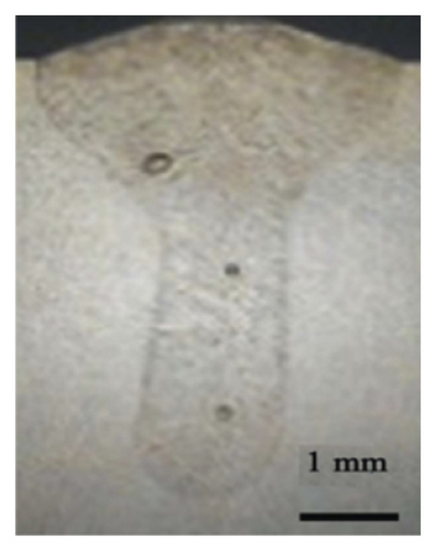
The HAZ in the ultrafine-grained steel was a major concern in many studies [21, 22]. In the HAZ, the microstructure of the ultrafine-grained steel undergoes severe transformations due to the influence of the welding thermal cycle, and the structure of the overheated zone changes significantly under the influence of the welding heat [21]. To investigate the microstructure and mechanical properties of the ultrafine-grained steel under laser penetration welding, the metallography of the cross section of the weld bead should be studied. The samples of ultrafine-grained steel were provided by Angang Steel Company Limited. The mechanical properties of the plate of AN420s-grade steel with dimensions of 60 mm × 30 mm × 8 mm were obtained through an experimental tension test using a SUNS UTM5000 electronic tensile testing machine under an ambient temperature of about 0°C. The mechanical properties of the AN420s-grade steel plate are shown in Table 1, where σs is the yield strength, σb is the tensile strength, and δs is the extensibility.
| Steel grade | Thickness (mm) | σs (MPa) | σb (MPa) | δs (%) | Remarks | |
|---|---|---|---|---|---|---|
| AN420s | 8 mm | 950 | 1080 | 12 | Transverse | |
| 940 | 1050 | 12 | Longitudinal | |||
| 945 | 1025 | 13 | 45° | |||
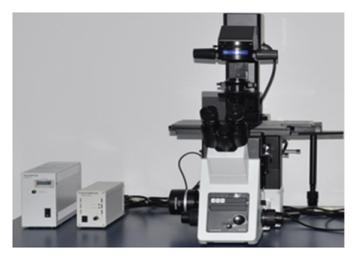
In this study, an IPG-YSL-10000 fiber laser welder with a minimum spot diameter of 0.72 mm and an argon gas flow rate of 15 L/min were used to weld the samples. The chemical composition of the weld bead was determined using an FLS980-stm Edinburgh fluorescence spectrometer and an Olympus GX71 metallographic microscope (Figure 2). The instruments used in this study are shown in Figure 2.

2.2. Constitutive Coupling Relation
| Al | C | Fe | Mn | Nb | P | S | Si | Ti | V |
|---|---|---|---|---|---|---|---|---|---|
| 0.015 | 0.11 | 97.062 | 1.71 | 0.087 | 0.22 | 0.016 | 0.46 | 0.15 | 0.17 |
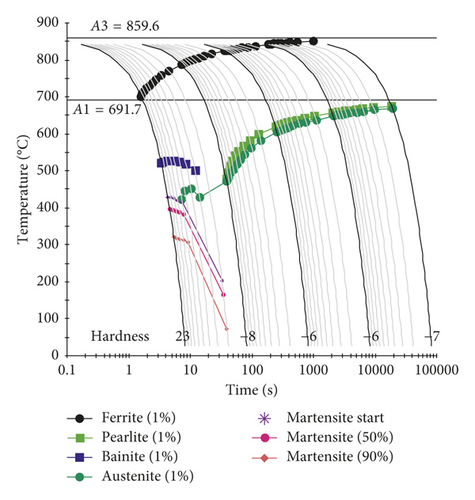
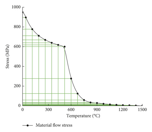
Figure 4 shows the material flow stress of ultrafine-grained AN420s-grade steel at different temperatures between the solidus and liquidus temperatures. A softening phenomenon occurs at a temperature above 500°C, and liquefaction of the material occurs at a temperature of about 1455°C, at which point the metallic state in the molten pool can be regarded as liquid. The material flow stress dramatically decreases from 610 MPa to about 50 MPa at a temperature above 500°C. The region beneath the material flow stress curve in Figure 4 can be considered a safety zone in which cracks will not form.
2.3. FEA Model
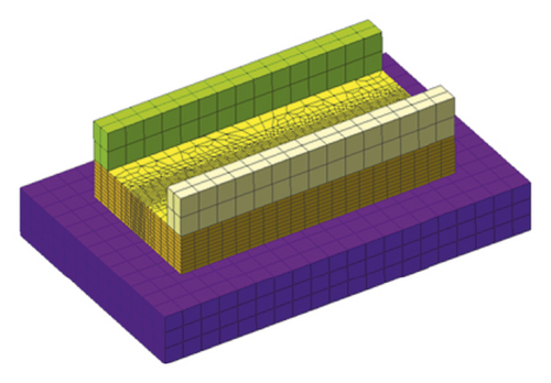
The finite element analysis (FEA) model of the ultrafine-grained AN420s-grade steel in the form of a vehicle component with a joint fabricated by pressure welding was created using the HyperWorks software. Subsequently, the FEA model was imported into the Simufact Welding software to analyze the laser penetration welding process. Two different welding conditions were used in this investigation. The FEA model is shown in Figure 5, the input data for the FEA model are shown in Table 3, and the welding conditions are shown in Table 4.
| Input data | Welding plate | Clamp | Support plate |
|---|---|---|---|
| Element size | Weld bead: 0.5 mm; base metal: 1.5 mm | 2.5 mm | 3 mm |
| Clamping force (kN) | 0.3 | 0.3 | 0.3 |
| Heat exchange coefficient | Air heat exchange coefficient: 20 W/(m2·K); weldment heat exchange coefficient: 1000W/(m2·K) | ||
| Welding parameters | Power (kW) | Speed (mm/s) | Holding force (kN) | Defocusing distance (mm) |
|---|---|---|---|---|
| 1st condition | 5.0 | 10.0 | 0.3 | 3 |
| 2nd condition | 5.0 | 20.0 | 0.3 | 3 |
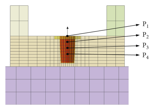
As shown in Figure 5(a), the total number of elements was 20040, and the ambient temperature was 20°C. To investigate the changes in the temperatures and stresses in the molten pool, four trace points were assigned. As shown in Figure 5(b), the trace points P1, P2, P3, and P4 were set to collect the residual stress and temperature information in the molten pool.
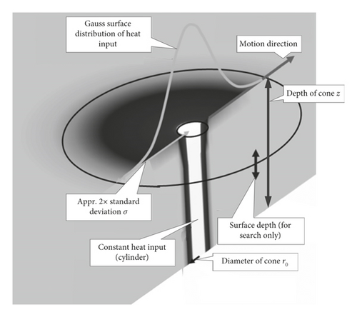
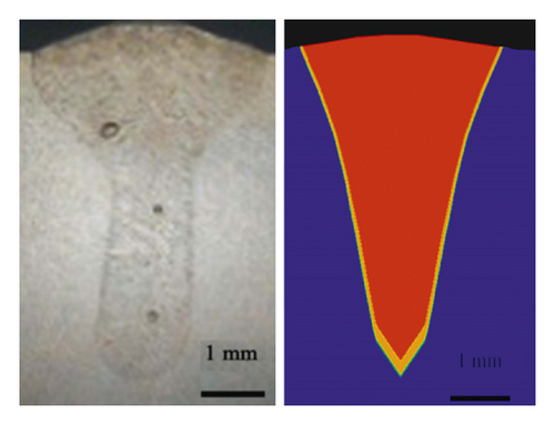
The characteristics of the laser welding heat source were the local concentration and the instantaneous and heterogeneous temperature field, and an accurate heat source model can improve the accuracy of the FE simulation results [25]. A compound heat source model comprising a cone heat source and Gaussian surface heat source was adopted in this study, and the accurate heat source model was obtained through careful collation from the surface to the root of the weld between the FEA model and the cross section of the weld bead. The heat source model collation is shown in Figure 6, and the error between the simulated and actual molten pools is shown in Table 5.
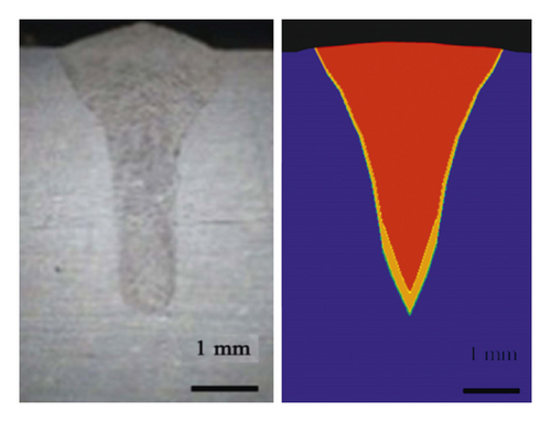
| Weld width (mm) | Weld depth (mm) | Maximum percentage error (%) | |||
|---|---|---|---|---|---|
| Experimental data | FEA model | Experimental data | FEA model | ||
| 1st condition | 4.0 | 4.068 | 5.4 | 5.387 | 0.2 |
| 2nd condition | 3.5 | 3.523 | 4.2 | 4.186 | 0.3 |
3. Results and Discussion
3.1. Simulated Results under the 1st Weld Operating Condition
The effects of the welding process parameters, including the laser power, welding speed, holding force, and defocusing distance, were studied. For the 1st welding condition, the parameters were a laser power of 5.0 kW, a weld speed of 10.0 mm/s, a holding force of 0.3 kN, and a defocusing distance of 3.0 mm. Nonuniform thermal expansion and contraction due to different temperatures during the heating and cooling sequence of the welding process resulted in tensile and compressive residual stress fields in and near the weld region [26]. Figure 7 shows the temperature evolution at the trace points in the molten pool. Figures 8(a)–8(c) show the residual stresses at the trace points at different times.
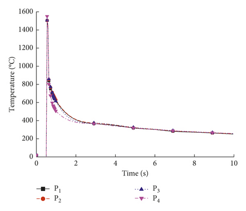

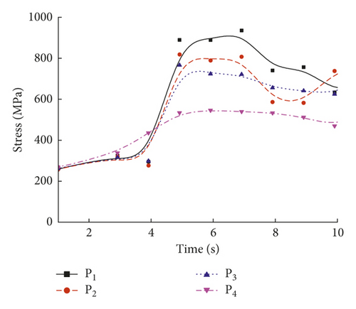
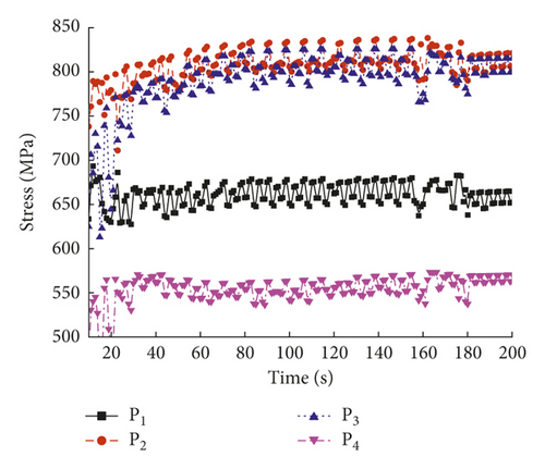
As shown in Figure 7, the temperature varied with time at the four trace points. The temperature in the molten pool increased dramatically from 20°C to a maximum temperature above 1570°C in a short period of 0.5 s, after which the temperature deceased during the cooling process. As shown in Figure 8, the residual stresses varied with time at the four trace points, and the residual stress curves can be divided into four stages: (1) the metal melted, and the stress value was below 3 MPa; (2) the metal solidified, and the stress value was below 200 MPa; (3) the molten pool began to cool, and the maximum stress occurred at about 7 s; and (4) the stress fluctuated about a certain value and finally reached a steady state. The residual stresses at the four trace points eventually stabilized to constant values, and the steady-state values are shown in Table 6.
| Trace point | P1 | P2 | P3 | P4 |
|---|---|---|---|---|
| Steady-state value of stress (MPa) | 650 | 820 | 800 | 570 |
According to Table 4, the steady-state residual stress values at the trace points were in the following order: P2 > P3 > P1 > P4. Under the 1st welding condition, the highest residual stress occurred in the middle of the welding plate.
3.2. Simulated Results under the 2nd Weld Operating Condition
For the 2nd welding condition, the parameters were a laser power of 5.0 kW, a weld speed of 20.0 mm/s, a holding force of 0.3 kN, and a defocusing distance of 3.0 mm. Figure 9 shows the temperature evolution at the trace points in the molten pool. Figures 10(a)–10(c) show the transient residual stresses at the trace points at different times.
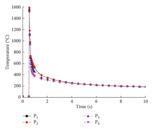
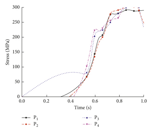
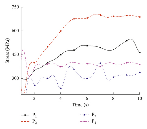
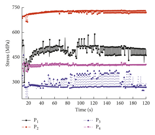
As shown in Figure 9, the temperature varied with time at the four trace points. Compared to the 1st welding condition, the highest temperature in the molten pool under the 2nd welding condition increased by about 5% from 1530 to 1600°C. As shown in Figure 10, the residual stresses varied with time at the four trace points, and the residual stress curve can be divided into four stages: (1) the metal melted, and the stress value was below 3 MPa; (2) the metal solidified, and the stress value was below 200 MPa; (3) the molten pool began to cool, and the maximum stress occurred at about 6 s; and (4) the stress fluctuated about a certain value and finally reached a steady state. The residual stresses at the four trace points eventually stabilized to constant values, and the steady-state values are shown in Table 7.
| Trace point | P1 | P2 | P3 | P4 |
|---|---|---|---|---|
| Steady-state value of stress (MPa) | 475 | 720 | 280 | 410 |
According to Table 4, the steady-state residual stress values at the trace points were in the following order: P2 > P1 > P4 > P3. Under the 2nd welding condition, the highest residual stress occurred in the middle of the welding plate.
3.3. Discussion
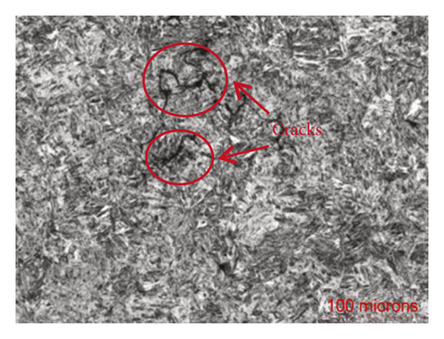
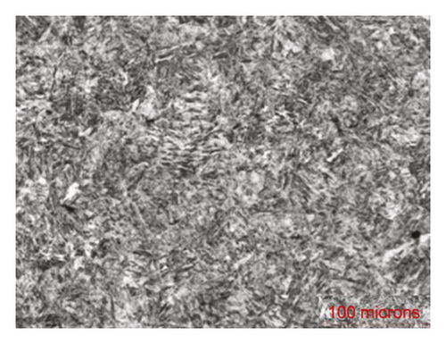
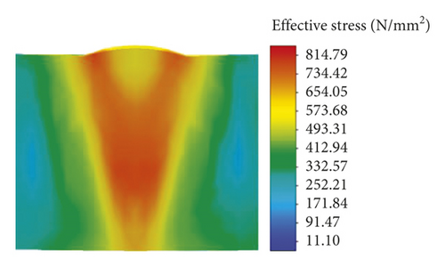
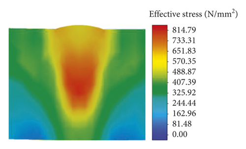
The results from the two different sets of welding parameters indicated that the highest residual stresses occurred in the middle of the welding plate, which corresponds to the trace point P2. However, the highest value of residual stress under the 2nd welding condition was significantly less than that under the 1st welding condition. When the welding speed increased and the weld pool geometry became tapered, the solidification cracks will be more concentrated and in positions near the centerline. Under this condition, the liquid flow rate was high and the rate of volume change was low. To investigate the effects of the residual stress on the solidification cracking behavior, a comparison between the experimental results and the predicted stress distributions under the two operating conditions is shown in Figure 10. The metallography of the cross sections of the weld beads under the two welding conditions was obtained using the Olympus GX71 metallographic microscope.
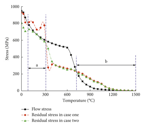
Figure 11 shows the cracks observed in the molten pool under the 1st welding condition. Upon increasing the weld speed from 10.0 to 20.0 mm/s for the 2nd welding condition, no cracks formed. Sheikhi et al. [27] reported that a low solidification rate and a small vulnerable zone were ideal for producing a weld without any cracks. Figures 11(c) and 11(d) show that the stresses in the molten pool under the 1st welding condition were higher than those under the 2nd welding condition, and high stresses in the molten pool increased the liquid flow. The constitutive coupling relation between the temperature and material flow stress is shown in Figure 4. The residual stresses at the trace point P2 at different temperatures were extracted and compared to the material flow stress curve.
- (1)
In the temperature range of interval b, the residual stresses under the two different welding conditions were higher than the material flow stresses. The weld bead was not completely solidified, and the state of the molten pool was a mixture of solid and liquid. The liquid still available between the solid cells was continuous and could move easily, since the solid cells have not yet coalesced, and compensates for the deformation induced by shrinkage and thermal stresses. Thus, for temperatures in the interval b, cracks will occur.
- (2)
In the temperature range of interval a, the weld bead was completely solidified, and the solid cells coalesced. The residual stresses under the 1st welding condition were higher than the material flow stresses, and cracks will form in this case. The residual stresses under the 2nd welding condition were lower than the material flow stresses, and cracks will not form in this case. These conclusions are in good agreement with the experimental results.
- (3)
The residual stresses under the two different welding conditions were nearly equal when the temperature was above 400°C. The residual stresses under the 1st welding condition quickly exceeded the residual stresses under the 2nd welding condition, indicating that cracks will form during the cooling process of the molten pool. This also explains why a reasonable increase of the welding speed can prevent solidification cracks in the laser penetration welding process of ultrafine-grained steel.
4. Conclusions
- (1)
At the same temperature and position in the molten pool, when the residual stress is higher than the material flow stress of ultrafine-grained steel, cracks will form in the weld bead.
- (2)
A reasonable increase of the welding speed can decrease the residual stress in the molten pool and enhance the laser penetration welding quality for ultrafine-grained steel.
- (3)
The proposed criterion obtained through the comparison of the residual stress and material flow stress curves of the ultrafine-grained steel can provide a new method to evaluate the formation of solidification cracks in weld beads.
Conflicts of Interest
The authors declare that they have no conflicts of interest.
Acknowledgments
The authors gratefully acknowledge the use of the services and facilities of AVIC Hubei Aviation Precision Machinery Technology Co, Ltd. and Hubei Key Laboratory of Power System Design and Test for Electrical Vehicle. This research was funded by the Youth Project of Hubei Provincial Department of Education (No. Q20172603), Hubei Superior and Distinctive Discipline Group of Mechatronics and Automobiles (No. XKQ2018065), and Hubei Superior and Distinctive Discipline Group of Mechatronics and Automobiles (No. XKQ2018009).
Open Research
Data Availability
The data used to support the findings of this study are available from the corresponding author upon request.


