Reliability Analysis of the Reconfigurable Integrated Modular Avionics Using the Continuous-Time Markov Chains
Abstract
The integrated modular avionics (IMA) has been widely deployed on the new designed aircraft to replace the traditional federated avionics. Hosted in different partitions which are isolated by the virtual boundaries, different functions are able to share the common resources in the IMA system. The IMA system can dynamically reconfigure the common resources to perform the hosted functions when some modules fail, which makes the system more robust. Meanwhile, the reliability of the reconfigurable integrated modular avionics becomes more complicated. In this paper, we firstly model the IMA as a joint (m, k)-failure tolerant system with the consideration of its reconfigurable capability. Secondly, the continuous-time Markov chains are introduced to analyze the reliability of the IMA system. Thirdly, we take the comprehensive display function hosted in the IMA system as an example to show the practical use of the proposed reliability analysis model. Through the parameter sensitivity analysis, different failure rate λ and priority order of different modules are chosen to analyze their impact on system reliability, which can provide guidance to improve the reliability of the IMA system during a dynamic reconstruction process and optimize resource allocation.
1. Introduction
In recent years, the integrated modular avionics (IMA) concept has been introduced to replace the traditional federated avionics [1]. In the federated avionics system, each function (e.g., autopilot, yaw damping, and displays) which uses dedicated communication, I/O, and computing resources is only loosely coupled to other functions [2]. Because the demand for more powerful and cost-effective avionic systems emerges, the federated avionics becomes not suitable for large-scale avionics. The IMA provides a common shared resource for several functions, which reduces the space, weight, and power requirements of the aircraft; therefore, both maintenance and operating costs are reduced [3]. Many newly designed civil and military aircrafts, such as COMAC C919, Boeing 787, and US Air force F-22, have chosen the IMA architecture.
Using shared resource, IMA has the potential to proliferate faults among functions, for example, a faulty function might monopolize the computer and deny service to all the other functions sharing the processor. It is almost impossible for individual functions to protect themselves against this kind of faults since their functions depended on the shared resources [4]. Furthermore, IMA implementations would allow applications with different safety-criticality levels to reside on the same platform. So, various partitioning technologies are introduced to the IMA to guarantee that each function will not be affected by other corrupt functions. In [5], spatial partitioning and temporal partitioning were proposed to isolate the memory and time resources for each function. The industry standard ARINC 653 [6] standardized a partitioned software architecture for IMA; it defined the application executive (APEX) interface which ensures the spatial and temporal partitioning of the avionics functions. Taking the communication needs of each function into account, Tu et al. [7] and He and Li [8] proposed the concept of network partition to allocate specified network bandwidth for each function. Zhou et al. [9] and Zhou and Xiong [10] proposed a resource allocation method for different functions to meet their various needs.
All the mentioned works tried to achieve the goal of robust partitioning [11] that offers the same level of isolation equivalent to the federated avionics. In fact, the partitioning mechanisms are provided either by hardware (such as memory management unit [12]) or software (such as intended segment analysis [13]). The failure or defect of the hardware and software can affect the robustness of the partitioning mechanism. In addition to the effectiveness analysis of the partitioning mechanism, the reliability of the partitioning mechanism themselves should also be considered. Chen et al. [14] analyzed the reliability of the avionics networks. Conmy and McDemid [15] illustrated the failure models of IMA. Suo et al. [16] analyzed the safety of the IMA from the airworthiness aspect. Wan et al. [17] used the stochastic Petri net (SPN) method to analyze the performability of the HM/FM strategies. The papers that focused on the reliability analysis of the IMA system reconfiguration are rare.
In this paper, the (m, k)-failure tolerant model is proposed to model the reconfigurable features of the IMA system and the continuous-time Markov chains are introduced to describe the state of the IMA reconfiguration. Then, a numerical example is given to show the practical use of the proposed reliability analysis model by listing reliability expressions. Finally, the sensitivity of the parameters λ and Pij that affect the reliability of the comprehensive display system is analyzed. The influence rules of parameters λ and Pij on system reliability are obtained, which can provide guidance for the resource allocation optimization of IMA.
2. The Reconfigurable Integrated Modular Avionics
2.1. Integrated Modular Avionics
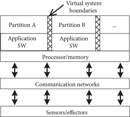
The IMA is comprised as a set of shared hardware and software resources. The IMA platform is partitioned into several partitions which can host one or more functions. Different partitions are isolated by the virtual system boundaries in both spatial and temporal dimensions. The platform manages all the resources to provide communications, computing capabilities, and interfaces to different functions. This architecture qualifies IMA with highly configurable capability of resources, which means that it is convenient to allocate resources to meet different needs of different functions and reallocate resources if any functions fail. So, the reliability analysis of the IMA partitioning mechanisms should take the failure tolerance of the IMA architecture into consideration. The system model is shown in Figure 1.
In the actual IMA system, different IMA system functions are configured by different types of core processing modules. As shown in Table 1, the A380 aircraft configures most of the aircraft functions to 7 types of 22 CPIOMs to support the system’s requirements of residing functions [18].
| Module type | Number |
|---|---|
| CPIOM-A | 4 |
| CPIOM-B | 4 |
| CPIOM-C | 2 |
| CPIOM-D | 2 + 1 (optional) |
| CPIOM-E | 2 |
| CPIOM-F | 4 |
| CPIOM-G | 4 |
| IOM | 8 |
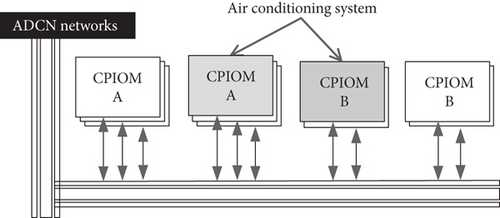
The same function can host in different CPIOMs to implement multiple backup systems, such as the ATA 21 air conditioning system in the A380 residing on two different types of hardware modules, CPIOM-A and CPIOM-B as shown in Figure 2.
2.2. Reconfiguration Process
Dynamic reconfiguration capability is the core technology of the IMA system, which not only reduces hardware redundancy and unexpected maintenance costs but also improves resource utilization, increases system flexibility, and enhances the ability of avionics systems to response to different missions and resource failures. Moreover, it can improve aircraft operational reliability while maintaining the current safety levels.
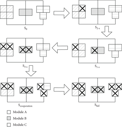
The reconfiguration behavior of the IMA system is controlled by the generic system management. When the reconfiguration is triggered due to the module failure, the generic system management obtains the configuration information from the blueprint system to realize the system reconfiguration. The following example illustrates the reconfiguration process of the IMA system. Assuming that an IMA system has 3 different types of modules, module A, module B, and module C. And function X can be implemented by any types of modules independently, while the amount of different types of modules required by function X varies due to the capability of each type of modules which is different. As shown in Figure 3, the system function is firstly implemented by the module A. When the number of type A modules is insufficient, it is implemented by the module B. When the module fails and the single -type module is not enough to implement the system function, the cooperative working mode is adopted. Function X will be implemented by a combination of module B and module C.

3. System Reliability Model
3.1. Assumptions
- (1)
Each module in the IMA system works in a binary state model that it is either functional or failed. Our work also can be extended to a multistate system which will take the performance degradation into account
- (2)
Module failures are independent and are not repairable
- (3)
The reconfiguration mechanism is reliable and will not fail
- (4)
All standby modules are in a hot backup state
3.2. Model of the Integrated Modular Avionics System
We assume that the IMA platform is consisted by N types of modules, PIMA = {M1, M2, …, MN}. And there are K functions hosted in the IMA platform, F = {f1, f2, …, fK}. We use an array to describe each kind of the module, Mi(Comi, Memi, Cali, Pi, Numi), where Comi is the communication capacity in which each module Mi can provide, Memi is the storage capacity in which each module Mi can provide, Cali is the calculation capacity in which each module Mi can provide, and Numi is the number of module Mi configured in the IMA platform. Pi = {pi1, pi2, …, pij}, where pij denotes the priority of module Mi for host function fj, which means the priority of module Mi is different for different host function fj. Because the requirement of different functions is varied and the capability of each type of module is different, functions can be implemented by different types of modules. denotes the number of module Mi required to perform function fj.
3.3. Reliability Model of the Reconfigurable Integrated Modular Avionics System
-
S0: all the m modules are functioning correctly
-
Si−s: the system works in a single-type module manner, which means that some modules fail, but the number of certain modules is sufficient to perform the function
-
Sc: the system works in a cooperative manner, which means that no single-type module can perform the function independently, but several types of modules can cooperatively work to perform the function
-
Sf: this state represents that the IMA system fails
The reconfiguration of the IMA system for certain functions is implemented according to the priority of the module for certain host function. In this paper, the reconfiguration mechanism for function fj is shown in the following steps.
Step 1. All the modules are functional, and the function fj is performed by module Mi. The system is in the state S0.
Step 2. When some module Mi fail and if the number of functional module Mi is more than , the function fj is still performed by module Mi. The system is in the state Si−s.
Step 3. When more module Mi fail and the number of functional module Mi is less than , the IMA platform reconfigures according to the priority of the module for host function fj. The function fj is performed by module Mt with ptj < pij. The system is in the state St−s.
Step 4. When more modules fail and no single-type module can perform the function independently, the IMA platform reconfigures in a cooperative manner. The system is in the state Sc.
Step 5. When the IMA platform cannot perform the function fj either in a single-type module manner or in a cooperative manner, the system is in the state Sf.
To simplify the model, the cooperative working mode among different modules is unidirectional, which means that the lower priority module for function fj can be replaced by a higher priority module but not vice versa.
The state transition diagram is shown in Figure 4.
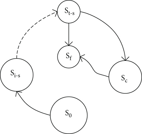
There is at least one type of the module that satisfies , i = 1, 2, …, N, and lu = 0, 1, 2, …, mu, u ≠ i. It is specified that the same type of the module has the same failure rate, and its reliability is expressed as ri(t). The definitions li and lu, respectively, represent the number of working modules Mi and Mu in the system. The vector m represents the number of modules configured, m = (m1, m2, …, mN). Other parameters are consistent with the previous definition. In the formula, the reliability of any module Mi that satisfies the condition is calculated and then, the reliability of the remaining N − 1 types of module Mu(u ≠ i) is calculated, as shown in the multiplication operation, by multiplying the two and finally adding all the conditions that satisfy , that is, the reliability of the system in the Si−s state.
All types of modules satisfy , and the equation is established. yc is defined as the state vector of the system, indicating the working state of various modules in the Sc state, yc = (l1, l2, …, lN). Define ψc(m) as the state vector set of the system. Other parameters are consistent with the previous definition. The reliability of each state vector yc is calculated, as shown in the multiplication operation, then calculated the reliability of each type of the module and multiplied it, and finally added all the conditions in the state vector set ψc(m), that is, the reliability of the system in the Sc state.
4. Model Example
4.1. Numerical Model
This section will give a numerical example to illustrate the feasibility of the proposed reliability analysis model. Suppose an IMA system has three types of modules: A, B, and C, that is, N = 3. The number of configuration for each type of the module is m = (4, 2, 3). For a function fj, the number of requirements for each type of the module is . The priority of each type of the module for function fj is pij = (1, 0, 2).
As shown in Figure 5, the reconfiguration process of IMA system function fj includes a total of six states. At the beginning, the system has no module failure and the system prefers the second-type module with the highest priority to execute the function fj. As the system runs, some modules fail. At this time, if , the system still prefers the type B module to execute function fj (S2−s), if , then the system will automatically perform the reconfiguration; it will reconfigure the function fj residing on the type B module to the higher priority type A module, and the system state is S1−s. Until the three types of modules satisfy , the system will not be able to implement fj through a single type of module and the system enters the joint working mode, that is, the high priority modules work in place of the low priority modules; this optimizes the performance of the system under limited resource conditions and enhances the system’s ability to cope with different missions. When the number of working modules of the system cannot meet the functional requirements, the system fails (Sfail).
4.2. Reliability Model of Display Function
In order to further study the impact of module configuration on the reliability of the reconfigurable IMA system, this section takes parameter sensitivity analysis by taking the comprehensive display function residing on the IMA platform as an example; by changing the failure rate and priority of each module, the reliability of the system is compared and analyzed.
4.2.1. Reliability Modeling
Based on the core processing module of IMA, the comprehensive display system cross-links with multiple systems such as aircraft communication, navigation, identification, and air data and attitude heading reference to realize the display of parameter information such as flight attitude, airspeed, and air pressure altitude [19]. The FAA Advisory Circular AC 25-11B provides clear guidelines for criticality of the display information [20], as shown in Table 2.
| Number | Display information | Criticality |
|---|---|---|
| 1 | Attitude | Critical |
| 2 | Airspeed | Critical |
| 3 | Barometric altitude | Critical |
| 4 | Vertical speed | Necessary |
| 5 | Corner velocity | Unnecessary |
| 6 | Sideslip/taxi, navigation, crew alerting | Necessary |
| 7 | Heading | Necessary |
| 8 | Power plant | Critical |
| 9 | Weather radar | Unnecessary |
The IMA system encapsulates these display information in different types of processing modules in the form of functional applications. According to the safety related section of part 6 of STANAG 4626 [21], functional applications of the same critical level are packaged in the same module. Therefore, the resource configuration of the IMA display function is shown in Table 3.
| Display information | 1, 8 | 2, 3 | 4, 6, 7 | 5 | 9 |
|---|---|---|---|---|---|
| Number of module A | 1 | 1 | 1 | 1 | 1 |
| Display information | 1, 8 | 2 | 4, 6, 7 | 3 | 5 | 9 |
|---|---|---|---|---|---|---|
| Number of module B | 1 | 1 | 1 | 1 | 1 | 1 |
So far, the establishment of the joint reliability model of the display function of the IMA system is completed, as shown in Figure 6.
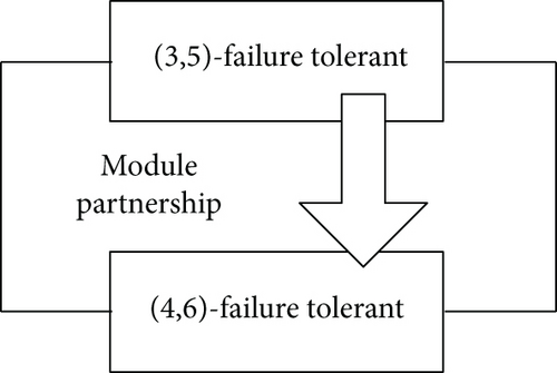
The IMA system performs display functions by configuring two types of modules, module A and module B, N = 2, m = (5, 6), , and PiDis. = (0, 1). Three type A modules reside for all critical, necessary display information functions, and two reside with unnecessary display information functions. Four type B modules reside for all critical, necessary display information functions, and two reside with unnecessary display information functions. When the module fails and the reconfiguration is triggered, the system can only turn off the unnecessary display information function, the key and necessary display information functions cannot be discarded. Therefore, the module that resides the unnecessary display information function will turn off its resident function according to the system requirements and reconfigure the critical and necessary display information functions. In addition, the system prefers the type A module to perform the display function.
4.2.2. Sensitivity Analysis of Parameter λ
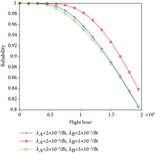
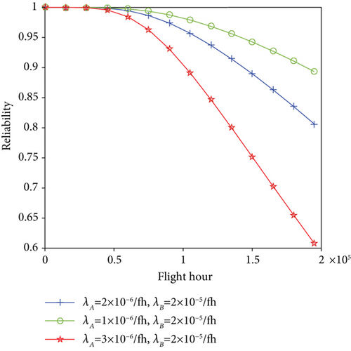
The parameter λ indicates the failure rate of the module, set the initial λ value of the type A module to λA = 2 × 10⁻⁶/fh and the type B module to λB = 2 × 10⁻⁵/fh. Then, keep the λ value of type A module unchanged and take the λ value of type B module as λB = 1 × 10⁻⁵/fh and λB = 3 × 10⁻⁵/fh, respectively; then, we obtain the relationship between system reliability and time as shown in Figure 7. Similarly, keep the λ value of type B module unchanged and take the λ value of type A module as λA = 1 × 10⁻⁶/fh and λA = 3 × 10⁻⁶/fh, respectively, as shown in Figure 8. Through observation, we found that for both types A and B of modules, when the value of λ is increased, the system reliability is reduced and when the λ value is reduced, the system reliability is improved. Meanwhile, we also found that the priority of the type A module is higher for the display function, so the system is more sensitive to the change of the λ value of the type A module. So, we can effectively improve the system reliability by configuring high priority modules with lower λ values.
4.2.3. Sensitivity Analysis of Parameter Pij
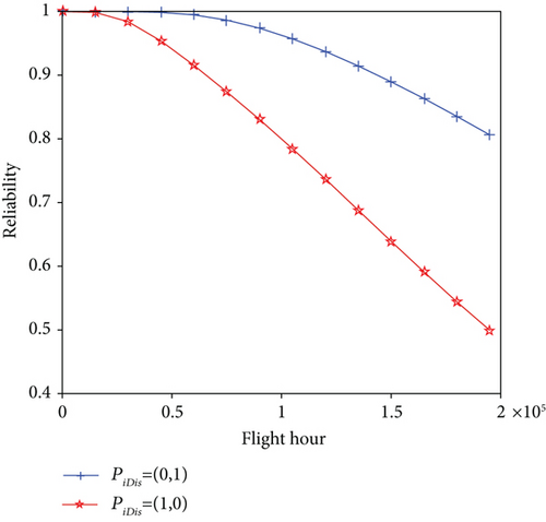
Since the different system function requirements for modules are different, we set the Pij value to characterize the priority of the module for function fj to better implement the reconfigurable configuration of the IMA system. For the display function, we change the priority of module A and module B, that is, PiDis. = (1, 0), the changes of the system reliability as shown in Figure 9. It can be seen from Figure 8 that the system reliability is significantly reduced. This is because after adjusting the priority of the type A module and the type B module, the system preferentially selects the type B module to perform the display function, but since the type B module has a larger λ value, the system reliability is degraded.
In summary, with the increase of the system module configuration, the economic cost of the system will be correspondingly improved and the correct and proper balance of the relationship between system reliability and economic benefits can provide effective guidance for system design.
5. Conclusion
This paper proposes a reliability methodology for the integrated modular avionics. Firstly, the reconfigurable ability of the IMA system is illustrated. Secondly, the joint (m, k)-failure tolerant model is introduced to analyze the reliability of the IMA system with the reconfigurable features. And a numerical example is given to show the practical use of the proposed reliability analysis model. The sensitivity of the parameters λ and Pij that affect the reliability of the comprehensive display system is analyzed. The influence rules of parameters λ and Pij on system reliability are obtained, which can provide guidance for the system design.
The Markov model can effectively describe the state transition of the system, while finding analytic solutions for Markov chain of complex systems is a big problem to overcome. We may pay great effort to find approximate solutions for the proposed Markov model of the reconfigurable IMA system.
Conflicts of Interest
The authors declare that they have no competing interests.
Acknowledgments
This paper was funded by Joint Funds of the National Natural Science Foundation of China and the Civil Aviation Administration of China (no. U1533105).
Open Research
Data Availability
The data used to support the findings of this study are available from the corresponding author upon request.


