Dynamic Stability and Control of a Manipulating Unmanned Aerial Vehicle
Abstract
This paper focuses on the dynamic stability analysis of a manipulator mounted on a quadrotor unmanned aerial vehicle, namely, a manipulating unmanned aerial vehicle (MUAV). Manipulator movements and environments interaction will extremely affect the dynamic stability of the MUAV system. So the dynamic stability analysis of the MUAV system is of paramount importance for safety and satisfactory performance. However, the applications of Lyapunov’s stability theory to the MUAV system have been extremely limited, due to the lack of a constructive method available for deriving a Lyapunov function. Thus, Lyapunov exponent method and impedance control are introduced, and the Lyapunov exponent method can establish the quantitative relationships between the manipulator movements and the dynamics stability, while impedance control can reduce the impact of environmental interaction on system stability. Numerical simulation results have demonstrated the effectiveness of the proposed method.
1. Introduction
Unmanned aerial vehicles (UAVs), especially the quadrotors, have developed rapidly and been widely applied in many ways [1], for example, aerial photography, power line patrol, and surveillance [2]. However, these applications mentioned all avoid interacting with the environments. For some environmental interaction tasks, the active operation of UAVs endowed with manipulator will greatly expand their range of applications, while it brings great challenges in dynamic stability for the whole system. As is well known, UAVs have many stability problems, such as shaking, out of control, and even crash, and if endowed with manipulators, UAVs stability will additionally be affected by manipulator movements and environment contacts. So dynamic stability researches of UAVs especially MUAVs are very necessary and important to ensure that the whole system is safe and reliable.
The field of MUAVs is still largely an immature one, but it has received great concern and some recent attempts have been made. Earlier studies focused on the installation of a lightweight gripper at the belly of the aircraft [3–5]. The gripper has less impact on the UAV, but the operating ability is very limited, so the later research mainly focused on changing the gripper device into a manipulator [6–9]. Manipulator, especially redundant manipulator, has flexible operation [10, 11]. However, manipulator movements and the environment contact will change the center of gravity position and reduce system stability [12]. On theoretical research, Euler Lagrange [13–15] and Newton-Euler [16–18] methods have been widely used to establish the dynamics model. But complex computation always brings great difficulties to model derivation.
As for nonlinear system stability analysis, the most commonly used method is Lyapunov’s stability theory [19–21]. It plays a very important role in the system stability proof and the controller design, and Lyapunov functions are needed when using this method. However, there is no constructive method available for deriving the functions, so it is quite difficult to establish the Lyapunov functions especially for the nonlinear system of MUAV with multiple variables, strong coupling, and underactuation. To solve this problem, Lyapunov exponent method has been introduced and widely used. Lyapunov exponents are the average exponential rates of divergence or convergence of nearby orbits in the state space, and they are related to the expanding or contracting nature of different directions in the n-dimensional phase space of a continuous dynamical system [22]. The concept of Lyapunov exponents provides a generalization of the linear stability analysis for perturbations of steady-state solutions to time-dependent solutions [23, 24]. Yang and Wu and Sun and Wu [25, 26] applied Lyapunov exponent method to study the dynamic stability of bipedal robots during disturbed standing. Abdulwahab et al. [27] used Lyapunov exponent method to analyze the lateral flight stability of unmanned aerial vehicles. In our previous work [28], quantitative relationship between the structural parameters of a quadrotor and the dynamic stability was established based on the Lyapunov exponent. By optimizing the different structural parameters, we improved the quadrotor dynamic stability. Since MUAVs usually need to interact with the environment, it is necessary to take some measures to ensure the stability of the system and avoid damage to the devices. Bartelds et al. [29] designed a compliant mechanism to allow the aerial manipulator to remain stable during and after impact. Alexis et al. [30] proposed a hybrid model predictive control framework to ensure the quadrotor stable and active interaction. In [31], impedance control was introduced to deal with the interaction between the end effector mounted on a ducted fan UAV and a vertical wall.
This paper focuses on the modeling and the dynamic stability analysis of a single DOF manipulator mounted on a quadrotor unmanned aerial vehicle. The Euler-Poincare equations are introduced to derive kinematics and dynamics model of the MUAV system. As for dynamic stability, the manipulator movements and the environmental interactions are considered separately. Lyapunov exponent method is used to analyze the stability affected by different manipulator movements and then the Newton-Euler recursive method is used to quantify the coupling between the manipulator and the quadrotor, after which coupling compensation is considered in the controller design. In order to ensure stability and safety when the end effector of the manipulator interacts with the environment, an impedance controller is designed. Numerical simulations illustrate the effectiveness of the controller in the force-constrained space as well as the transition from the free space to the force-constrained space.
The rest of this paper is organized as follows. Section 2 presents the overall system model. In Section 3, dynamics stability and coupling characteristics of the system due to manipulator movements are analyzed. In Section 4, the complete interaction control architecture is proposed, and its effectiveness is demonstrated in Section 5 by means of numerical simulation. Finally, some conclusions are presented in Section 6.
2. System Modeling
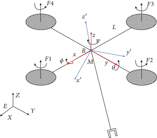
The system considered in this paper, depicted in Figure 1, is composed of a quadrotor vehicle equipped with a single DOF manipulator. One end of the manipulator is mounted at the geometric center of the four quadrotors (assuming that the geometric center coincides with the center of mass of the quadrotor).
-
m1: Mass of the quadrotor vehicle
-
m2: Mass of the manipulator
-
g: Local gravity acceleration
-
L: Length of the quadrotor from the center of mass to rotor axis
-
Rq: Rotor radius
-
R: Length of the manipulator from the root to the center of mass
-
S: Length of the manipulator
-
CQ: Coefficient of the rotor torque
-
CT: Rotor tensile force coefficient
-
ρ: Local air density
-
Ix, Iy, and Iz: Quadrotor moment of inertia of axis x, y, and z
-
Jy: Moment of inertia of the manipulator link about its center of mass
-
wi: ith rotor speed.
- (i)
Define joint data:
-
r1 = {6}; H1 = IdentityMatrix [6];
-
q1 = {ϕ, θ, ψ, x, y, z}; p1 = {p, q, r, u, v, w};
-
r2 = {1}; H2 = {{0}, {1}, {0}, {0}, {0}, {0}};
-
q2 = {a}; p2 = {b};
-
JointLst = {{r1, H1, q1, p1}, {r2, H2, q2, p2}};
-
- (ii)
Define body data:
-
com1= {0, 0, 0}; mass1 = m1; out1 = {2, {0, 0, 0}};
-
Inertia1 = {{Ix, 0, 0}, {0, Iy, 0}, {0, 0, Iz}};
-
com2 = {0, 0, −R}; mass2 = m2; out2 = {3, {0, 0, -S}};
-
Inertia2 = {{0, 0, 0}, {0, Jy, 0}, {0, 0, 0}};
-
BodyLst = {{com1, {out1}, mass1, Inertia1}, {com2, {out2}, mass2, Inertia2}};
-
- (iii)
Define interconnection structure:
-
TreeLst = {{{1, 1}, {2, 2}}};
- (iv)
Define potential energy and nonconservative generalized input force/torque:
-
PE = 0;
-
T1 = U2; T2 = U3; T3 = U4;
-
Q = {T1, T2, T3, 0, 0, U1, T4};
- (v)
Modeling.
-
{JV, JX, JH, MM, Cp, Fp, pp, qq} = CreateModel [JointLst, BodyLst, TreeLst, g, PE, Q, JV, JX, JH];
-
Equations = MakeODEs [pp, qq, JV, MM, Cp, Fp, t]
3. Dynamic Stability Analysis
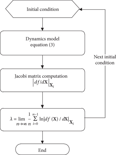
It can be known that if λ > 0, limn→∞ε · enλ → ∞ will tend to infinity, which shows that the disturbed trajectory and the original trajectory of the system is separated with time and the system is chaotic, and if λ < 0, limn→∞ε · enλ → 0 will tend to zero, which illustrates that after disturbed, the system can reach the original system state again and the system is insensitive to the disturbance and stable.
According to the method described above, when the quadrotor is hovering, Lyapunov exponents of the system are calculated separately with different manipulator movements. When setting the number of iterations to 100 and the initial state ([q, p]T) of the MUAV system to [0, 0, 0, 0, 0, 0, 0, 0, 0, 0, 0, 0, 0, 0]T, the Lyapunov exponents of the system can be obtained. For a clear analysis, Lyapunov exponents of the quadrotor attitudes and manipulator joint angle are shown in Figures 3 and 4. When the desired joint angle ad of the manipulator is 0, that is, the quadrotor and the manipulator are relative stationary, the Lyapunov exponents spectrum is shown in Figure 3. Similarly, set ad = sina, then the Lyapunov exponents spectrum of the quadrotor attitudes and manipulator joint angle are shown in Figure 4.
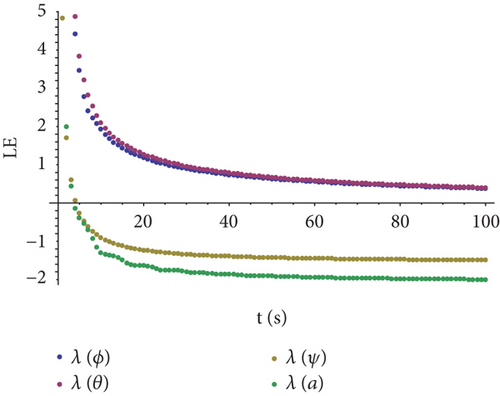
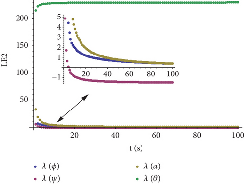
From Figures 3 and 4, we can see that the Lyapunov exponents of Figure 3 are less than 0 or tend to be 0, while in Figure 4, there is one exponent that is greater than 200 with no tendency to 0. In comparison with these two figures, when there is relative motion between the manipulator and the quadrotor, the dynamic stability of the whole system is obviously getting worse; in severe cases, the whole system may get unstable.
From Figures 3 and 4, it can be seen that the Lyapunov exponents of the corresponding roll angle and yaw angle are almost the same while the Lyapunov exponents of the corresponding pitch angle and manipulator joint angle differ. For a clearer analysis, the Lyapunov exponents of pitch angles and joint angles are shown in Figures 5 and 6.
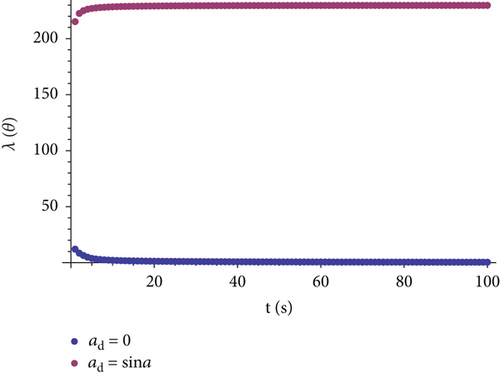
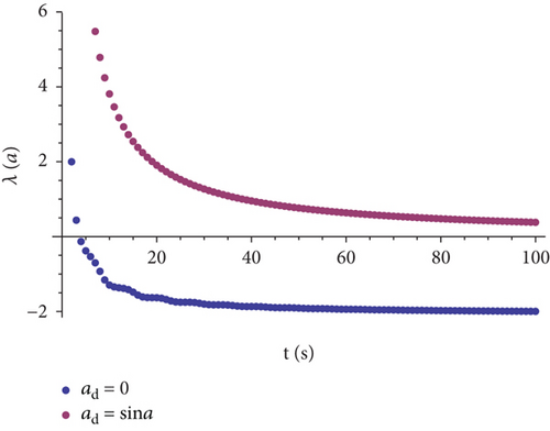
Figure 5 shows that the Lyapunov exponent of the pitch angle in the condition of ad = sina is much larger than that of ad = 0, which indicates that the dynamic stability gets worse when the manipulator movements exist and the manipulator movements will affect the quadrotor pitching motion, and even may lead to the instability.
According to Figure 6, the joint angle Lyapunov exponent is less than 0 when ad = 0. However, the exponent changes when ad = sina, that is, relative motion between the robot arm and the quadrotor presents, which indicates that manipulator motion, in turn, is affected by the quadrotor motion.
From Figures 5 and 6, it can be concluded that the quadrotor pitching motion and the manipulator motion are coupled. This coupling characteristic will have very bad effects on the subsequent control and practical applications, so it is necessary to analyze and quantify the coupling and then in the controller design, coupling, and compensation is needed.
Similar to the space manipulator [34], Newton-Euler recursive method [35] is used to quantify the coupling. Suppose that the quadrotor is the root of the manipulator, which can be thought link 0 and from the root to the end effector, the linear velocity, angular velocity, and acceleration of each link can be calculated. With velocity and acceleration, the force and torque on each link are derived backwards. Finally, the force applied on the quadrotor due to the manipulator movements can be calculated, and the derivation process is as follows.
For simplicity, some symbols are defined. Let jωi and jvi denote the angular velocity and the linear velocity of link i with respect to the link frame ∑j. αi denotes the joint angle of link i. represents the derivative of time. ijR is the rotation matrix of the ∑i relative to ∑j. jpi is the position of the ith joint in ∑j, and jhi represents the axis of rotation of link i in ∑j.
In order to verify the quantized coupling, firstly, simple PID controllers are designed to control attitude and height of quadrotor and joint angle of the manipulator. Then, PID controllers with regard to coupling compensation are also applied to control the quadrotor and the manipulator. For the two cases, the pitch angle simulation is presented in Figure 7.
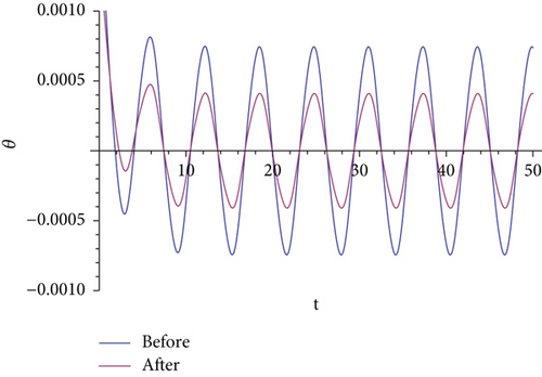
From Figure 7, the coupling exists both with and without feed-forward compensation. However, after compensation, the amplitude of the pitch angle oscillation is significantly decreased. Therefore, quantized coupling, when applied to control compensation, can play a certain role in controller design.
4. Control Scheme
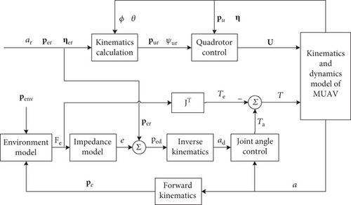
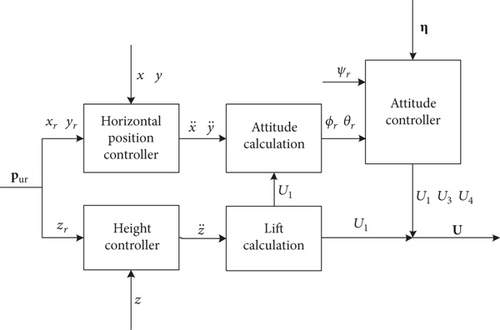
As is shown in the impedance control block diagram in Figure 8, for the manipulator, a position-based impedance control (PBIC) is introduced and it includes a double control loop. The inner loop is position control and the outer loop is impedance control. According to the actual interaction force and desired impedance parameters, the outer loop generates position correction as represented in (21). When giving the reference position per, attitude ηer and joint angle ar of the end effector as well as the feedback roll and pitch angle, the reference position pur, and yaw angle ψr of the quadrotor can be obtained via a kinematics calculation algorithm proposed by [37]. Then with reference and the feedback position pu and attitude η of the quadrotor, the quadrotor controller can be designed.
5. Simulation
In order to validate the effectiveness of the controller, several simulations have been carried out in the MATLAB/Simulink environment. The purpose of the simulation is that when the quadrotor hovers at a specified point, the manipulator makes contact with a surface. Two cases are studied, that is, the desired trajectory tracking and the desired force tracking. For simplicity, we ignore friction and consider that interaction force is applied to only one direction. Reference position of the manipulator is set at xer = 0.1 m and a surface is located at xenv = 0.09 m with respect to ∑b. With the given reference position of the end effector, reference joint angle ar of the manipulator can be calculated via the inverse kinematics algorithm, and the value of ar is π/6. Besides these, the stiffness of the environment ke is 100. Md, Bd, and Kd are 1, 50, and 625, respectively. The initial condition of the simulation is set to q = [0, 0, 0, 1, 1, 1, 0]T. Simulation adopts variable step. The solver is ODE45 and simulation time is 20 seconds. The involved system parameters values are given in Table 1.
| Symbols | Values |
|---|---|
| m1 | 0.875 kg |
| m2 | 0.106 kg |
| g | 9.8 m/s2 |
| L | 0.225 m |
| R | 0.1 m |
| S | 0.2 m |
| CT | 1.0792−005 |
| CQ | 1.8992−007 |
| Rq | 0.125 m |
| ρ | 11.69 kg/m3 |
| Ix | 9.5065−003 kg/m2 |
| Iy | 1.00−002 kg/m2 |
| Iz | 1.658−002 kg/m2 |
| Jy | 2.37−003 kg/m2 |
5.1. Desired Trajectory Tracking
Simulation results of the end effector during the transition from free motion to interaction are shown below. The quadrotor UAV firstly flies to a position of pu = (1, 1, 1) with respect to ∑, after which it hovers over this point and then the manipulator with an initial joint angle value of 0 approaches the wall and makes contact with it until the end effector arrives at the desired position.
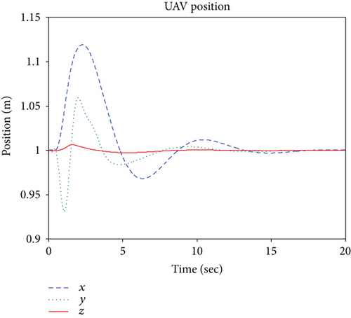
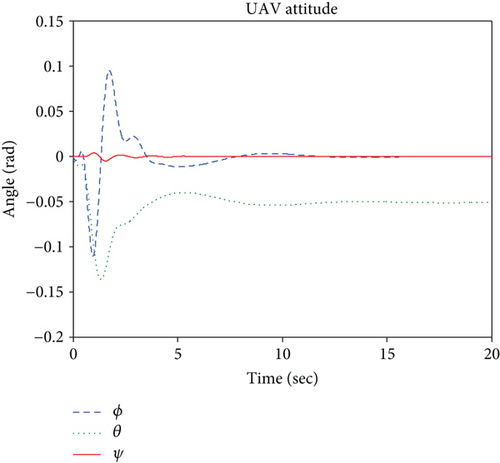
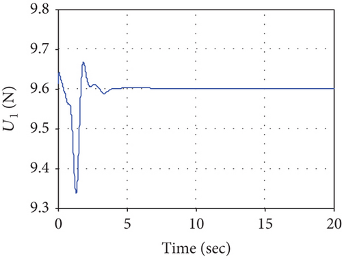
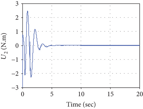
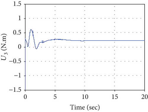
Simulation results of the UAV are shown in Figures 10–12. When the quadrotor hovers at the point pu, the manipulator operates, which results in a quadrotor oscillation. The quadrotor tends to stabilize after the controller works, but the coupling caused by the manipulator leads to a slight tilt of the quadrotor in the pitch angle (shown in Figure 11) and the pitch control torque U3 (shown in Figure 12) is no long 0. The tilt can allow the UAV to generate a force to offset the contact force. Figure 10 shows that the UAV translation in the x-axis is obviously affected due to the influence of the UAV pitch motion. The manipulator movements and interaction between the end effector and the surface affect the ability of the system, and the control force or torques change so that the UAV can return to a stable state quickly.

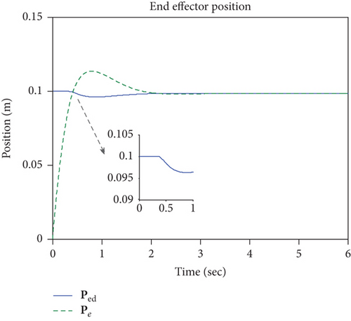
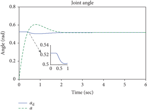
Figures 13–16 shows the simulation of the end effector. From 0 to about 0.4 seconds, the manipulator moves in the free space, and the interaction force is 0 (shown in Figure 15), which results in a position correction value of 0 and the reference position is equal to the desired position during this time period (shown in Figure 13). After 0.4 seconds, the end effector contacts the surface, and the interaction force is no longer 0. Figure 15 shows that when the end effector makes contact with the surface at a certain speed, the interaction may keep growing due to inertia, then the impedance controller works so that the interaction force and the end effector position meet the desired dynamic relationship. Figure 13 shows that the desired position of the end effector is less than the given reference value 0.1, which can be explained by the fact that when the desired dynamic relationship mentioned above meets the requirements, the end effector reaches a proper position to avoid an excessive contact force. This is why the impedance control can reduce the damage of the end effector and the interactive objects.
5.2. Desired Force Tracking
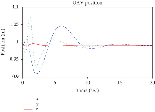
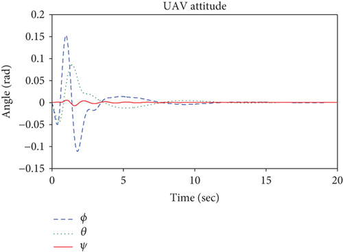
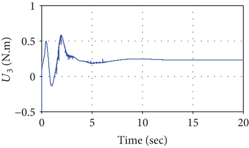
The desired force Fd is 1 N, and other simulation conditions are the same as the desired trajectory tracking simulation. Simulation results of the UAV are shown in Figures 17–23. Similar to the desired trajectory tracking, the UAV hovers at a position of pu = (1, 1, 1) with respect to ∑. Figure 17 shows that the UAV flies in a neighborhood of point pu and after about 13 seconds, the UAV tends to hovers although there is still a tiny error. Compared with Figure 11, Figure 18 reflects a better convergence effect especially the case of pitch angle and it reaches 0 despite the presence of interaction between the end effector and the environment. This is mainly because the given desired force Fd, which may be thought to offset the interaction force. Both simulations of the desired trajectory tracking and the force tracking indicate that the manipulator movements and the environment contacts have an impact on the UAV stability; however, the height and yaw motion suffer a relatively little impact. From Figure 19, due to the manipulator influence, it is can be seen that the UAV pitch control torque U3 is not 0 although the pitch angle can reach 0 after the controller works.
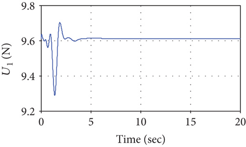
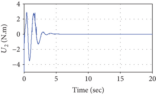
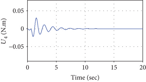
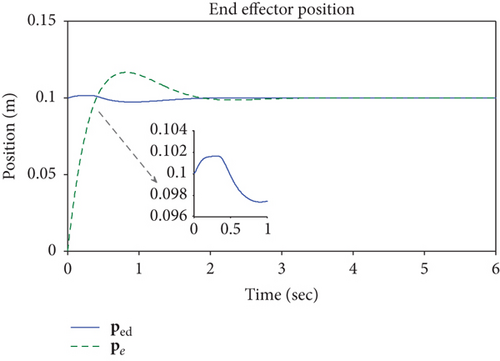
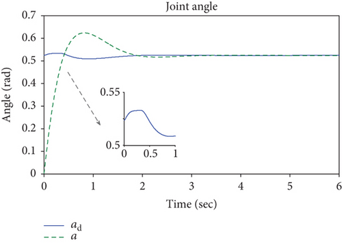
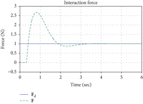

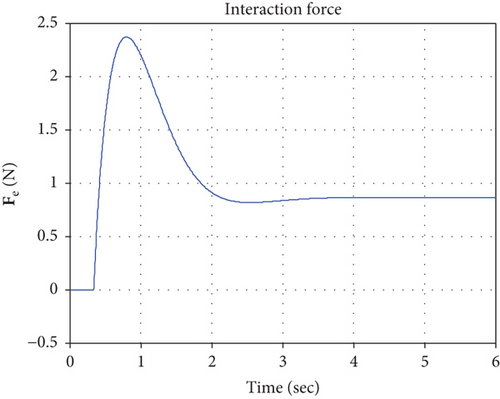
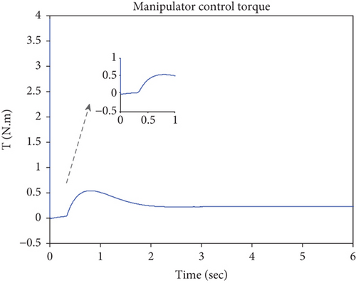
Figures 20–23 shows the simulation results of the end effector. From 0 to about 0.4 seconds, the manipulator moves in the free space, and the interaction force is 0, as shown in Figure 22. However, different from Figures 13 and 14, Figures 20 and 21 show that the desired position and joint angle of the manipulator changes during the movements in the free space. This can be explained by the desired impedance model (25), and position correction is not 0 due to the given desired force. After about 0.4 seconds, the controller works, and it tracks the desired force perfectly and the tracking error is 0, which results in a position correction value of 0 and the reference position is equal to the desired position. The joint control torque slightly increases to make the end effector reach the surface. Different from Figure 16, the joint torque decreases as the interaction force increases, as shown in Figure 23 and when the system gets stable, the torque remains a fixed value.
6. Conclusion
This paper has presented the model and the dynamic stability analysis of a manipulating unmanned aerial vehicle, and numerical simulation is used to test the work. The system modeling based on Euler-Poincare equation is simple and efficient by means of computer symbol derivation. Lyapunov exponent method used to analyze the dynamic stability just considering the manipulator movements has shown obvious advantages. It is constructive and simple for the exponent calculation when compared with Lyapunov’s stability theory. Simulation results illustrate that the coupling between the manipulator and the quadrotor will affect the dynamic stability of the MUAV, and the coupling compensation can reduce the influence. As for interaction dynamic stability, the proposed impedance controller is shown to be able to stabilize the system both in the free flight and in the presence of interaction.
Conflicts of Interest
The authors declare that they have no conflicts of interest.
Acknowledgments
The authors thank the anonymous reviewers for helpful and insightful remarks. Helpful discussions with Professor Wu Qiong on her guidance in Lyapunov exponent theory are gratefully acknowledged. This research is supported by the National Natural Science Foundation of China (51405243 and 51575283).


