Design of a Control System for an Organic Flight Array Based on a Neural Network Controller
Abstract
This paper presents a flight control system for an organic flight array (OFA) with a new configuration consisting of multimodularized ducted-fan unmanned aerial vehicles. The OFA has a distinguished advantage of assembling or separating with respect to its missions or operational conditions because of its reconfigurable structure. Therefore, designing a controller that can be flexibly applied in each situation is necessary. First, a dynamic modeling of the OFA based on a single ducted-fan vehicle is performed. Second, the inner loop for attitude control is designed through dynamic model inversion and a PD controller. However, an adaptive control component is needed to flexibly cope with the uncertainty because the operating environment of the OFA is varied, and uncertainty exists depending on the number of modules to be assembled and disturbances. In addition, the performance of the neural network adaptive controller is verified through a numerical simulation according to two scenarios.
1. Introduction
Unmanned aerial vehicles (UAVs) with many types, sizes, and ways of flight have been used in various fields during the past decades. Interest in vertical take-off and landing (VTOL) vehicles, in particular, greatly increased because having a space for a runway is not necessary, and hovering is easier than in fixed-wing UAVs. These features have recently been used for military purposes, such as surveillance of urban warfare and near-field reconnaissance. In addition, performing missions (e.g., communication relay, wide-area reconnaissance, and radar jamming) is possible because the field of application is diversified and because of the growth of technology. The VTOL UAVs are also utilized in the civil field for image photographing and in the aviation transport industry because of their advantages. Moreover, the VTOL UAVs have also been actively utilized for hobby and leisure and are classified into multirotor [1], coaxial [2], Coanda [3], and ducted-fan type [4].
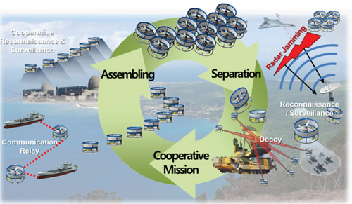
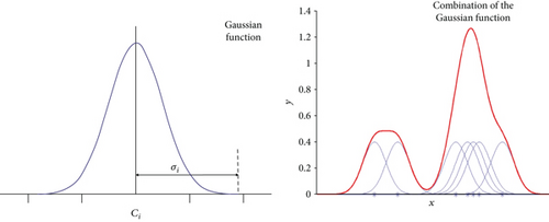
Although various VTOL UAVs are capable of hovering, their operation is restricted in the environment, where gusts or strong winds are constantly blown. Moreover, a disadvantage of having the thrust-to-weight ratio lower than that of a fixed-wing also exists. Therefore, many studies were conducted to overcome the disadvantages of the VTOL UAVs. Accordingly, studies have also been recently conducted to overcome the instability of the vehicle by using a controller that can more robustly cope with gusts and disturbances [5, 6]. Several studies were also performed to complement the disadvantages and overcome the payload limitation through the cooperation of several VTOL UAVs [7]. However, there is a limit in overcoming the disadvantages through the existing flight module in the situation when the mission becomes more diverse. Hence, a study is proposed to overcome the disadvantages by constructing a vehicle through physical assembling. In this way, the vehicle can have a higher robustness than when it is operated as a single vehicle. The vehicle can also have an advantage of increasing the payload according to the number of assembled vehicles. Moreover, organically coping with the mission becomes possible by changing the assembled shape in an environment, where reconnaissance is difficult in the field, such as indoor or in a narrow road. One of these studies is on the distributed flight array (DFA) conducted by the ETH Zurich of Switzerland. The vehicle used consisted of autonomous hexagonal single-rotor modules that are able to drive, dock with its peers, and fly in a coordinated fashion. The DFA can generate the thrust but cannot fly with a single module because it cannot remove the antitorque. Hence, the single-rotor modules must be combined to fly with other modules [8, 9]. The International Islamic University of Malaysia also conducted a study on autonomous flight vehicles with distributed flight array concepts. This module had triangular frames that can be combined with each module. In flight mode, the control gains are changed based on the in-flight data [10]. In this study, a similar concept with the DFA was used to overcome various disadvantages by assembling a ducted-fan vehicle. The operational concept that can be assembled and separated freely during flight was defined as shown in Figure 1 to adapt to the diversity of the mission [11]. However, the control performance greatly deteriorated because of the model uncertainty and the nonlinear disturbance when the assembling and separation modes were performed in flight. So, the model uncertainty that can occur in accordance with the operational concept of the organic flight array composed of ducted-fan vehicles is defined as the model inversion error of the process of DMI, and it is significant to verify whether such uncertainty is mitigated through the radial basis function neural network controller which enables control. This study proposed an adaptive control method to cope with the disadvantages and limitations of other studies on flight array by using the radial basis function neural network that can consider the nonlinear characteristics and model uncertainties. The dynamic model of the OFA in this process was defined based on the single ducted-fan vehicle [4]. A dynamic model of the OFA was then transformed into the affine system form to apply the dynamic model inversion technique [12]. Subsequently, the attitude control system was designed through a PD controller based on the affine system [13]. However, the model error was present between the model simulated by the model inversion process and the actual model. In addition, the adaptive control system that can compensate for the model error by applying the neural network control technique was also designed and added to the existing controller [14]. A radial basis function neural network with a simple structure that can guarantee the performance and minimize the amount of computation was applied because generating the adaptive control input in real time was necessary. The activation function of the hidden layer in this process was constructed by using a Gaussian function [15]. This paper is structured as follows: Section 2 describes the detailed modeling of a ducted-fan vehicle adopted in the OFA. The OFA dynamic equation of the affine system was then derived. Section 3 describes the design of the controller through a dynamic model inversion and a PD controller, which is the basic controller for attitude control. The adaptive controller of the neural network to cope with the uncertainty was also derived. Section 4 presents the numerical simulation results for each scenario. Section 5 summarizes the research conclusions.
2. Dynamic Model
2.1. Ducted-Fan Model Dynamics
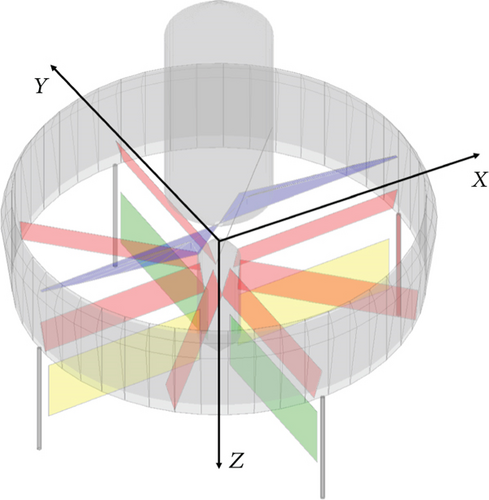
Figure 2 shows the simulation model defined based on the ducted-fan vehicle. The x-axis is defined as the direction similar to that of the aileron control surface, whereas the y-axis is defined as the direction similar to that of the elevator control surface. The z-axis is defined as the downward direction in which the yaw angle of the clockwise direction is set to a plus sign. The simulation model is basically composed of the duct, fuselage, rotor, stator, and control surfaces. The rotor that generates the thrust and the stator that counteracts the antitorque are placed inside the duct. Thus, the yaw axis stability is secured using the stator. Each control surface located directly under the duct structure is designed in a cross shape around the z-axis. This design creates a moment for the control of the roll, pitch, and yaw Euler angles. Defining the translational motion direction in advance is necessary because the ducted-fan vehicle has a symmetrical structure with respect to the z-axis. The coordinate axes are defined herein in accordance with the direction of the control surface. Table 1 shows the control surface direction and effect.
| Definition | Sense | Flaps | Effect |
|---|---|---|---|
 |
+δail | 1, 3 | +Mx |
| +δele | 2, 4 | +My | |
| +δrud | 1, 2, 3, 4 | +Mz |
- (1)
Rotor:
(4) -
In (4), bthr,1, bthr,2, btor,1 and btor,2 are the output values via the DFDC (Table 2).
- (2)
Fuselage: the fuselage generates a drag force proportional to the area along each axis. The force and the moment by the fuselage are defined as follows:
(5) -
Here, Stop and Sside are the cross-sectional areas along the direction of the fuselage, and ρ∞ is the density. The drag coefficients along each axis are defined as CD. The distance between the aerodynamic center and the center of gravity is defined as lfuse.
- (3)
Duct: the duct has a circular symmetrical shape around the z-axis. Therefore, duct modeling is performed by integrating the lift and the drag forces generated from the unit duct from 0 to 360°. The flow velocity around the duct surface is defined as the function of θduct as follows:
(6)where Vr is the flow velocity of the radial direction and Vz is the flow velocity in the direction of the rotation axis. The rotation angle about the z-axis, which rotates along the duct plane, is defined as θduct. The dynamic pressure and angle of attack can be written as follows using the flow velocity defined in (6):(7) -
The force and the drag per unit angle generated by the airfoil using (7) are as follows:
(8)where CL,duct and CD,duct represent the lift and drag coefficients for the duct airfoil, respectively. These parameters are derived from the empirical formulas. The total lift and drag can be defined by integrating the lift and the drag per unit angle from 0 to 2π as follows:(9) -
The lip moment induced by the lift imbalance phenomenon and the momentum drag generated by the reaction of the duct during the translational motion are included in the duct component.
-
Each component can be expressed as follows:
(10)where is the mass flow through the rotor and Cm,duct is the duct moment coefficient. The moments and forces generated by the duct considering (9) and (10) are as follows:(11) -
The lduct of (11) is the distance between the aerodynamic center of the duct having an airfoil shape and the center of the gravity point.
- (4)
Control surfaces: the control surfaces, which change the attitude of the vehicle by adjusting the direction of the wake generated by the rotor, are located directly below the duct. They perform the roles of an aileron, elevator, and rudder. The forces and moments generated by the control surfaces are defined as follows:
(12)where δr, Sr, lr, CL, and Qe represent the deflection angle, area, distance between the aerodynamic center and the center of the gravity point, lift coefficient of the control surface, and dynamic pressure, respectively. - (5)
Gravity: the gravity generates a force based on the body-fixed coordinate system whenever the attitude of the vehicle changes. The forces generated by the roll and pitch motion of the vehicle are defined as follows:
(13) - (6)
Gyroscopic moment: the gyroscopic moment is defined as a moment that is incidentally induced to the vehicle by the rotating rotor. Each component can be expressed as follows:
(14) -
The gyroscopic moment is a value proportional to the angular velocity and the RPM of the rotor. In (14), Nb, Jb, and ωr denote the number of blades, moment of inertia, and angular velocity of the rotor.
| Component | Parameter | Value |
|---|---|---|
| Thrust | bthr,1 | −1.5601e − 3 |
| bthr,2 | 4.1367e − 6 | |
| Torque | btor,1 | 9.0261e − 5 |
| btor,2 | −2.6851e − 8 | |
2.2. Organic Flight Array Model Dynamics
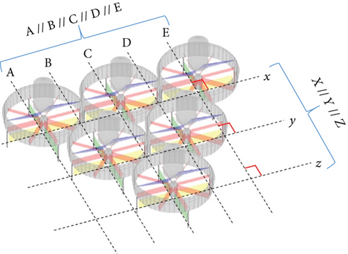
The control matrix G is defined by the area of the control surface of each module, induced velocity, and vertical velocity of the vehicle. The size of the matrix G varies depending on the number of combined vehicles, unlike the F matrix. Hence, the matrix size of G can be defined as .
3. Design of the Control System
3.1. Dynamic Model Inversion
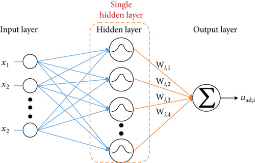
3.2. Adaptive Control System of the Neural Network
Assumption 1. There is a fixed point νad of at all d′ ∈ D′.
As a result, the model error can be canceled through the adaptive input and can be defined as using the components of (26) and (29).
3.3. Basis Function
| Channel | Input variables |
|---|---|
| Phi (ϕ) |
|
| Theta (θ) |
|
| Psi (ψ) |
|
3.4. Control System Structure
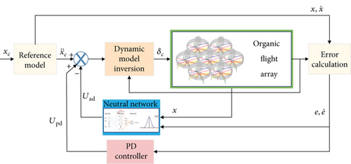
A PD controller was used, and the DMI method was applied herein as an inner loop for attitude control. A controller structure with an adaptive control input based on the neural network was additionally considered in a situation where a model error occurs. Figure 6 shows the control structure for the attitude control of the OFA.
4. Numerical Simulation
A numerical simulation was performed herein by applying the dynamic model inversion technique and the PD controller. The simulation result was analyzed according to the presence or absence of the NN by defining the scenario in which the uncertainty or the disturbance occurred. Each of the scenarios simulated the attitude control assuming a situation, in which an arbitrary model uncertainty is given, and simulated the path control in the situation where the strong disturbance continuously influences. Figure 7 shows the OFA model used in each scenario.

4.1. Scenario 1
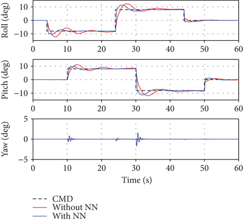
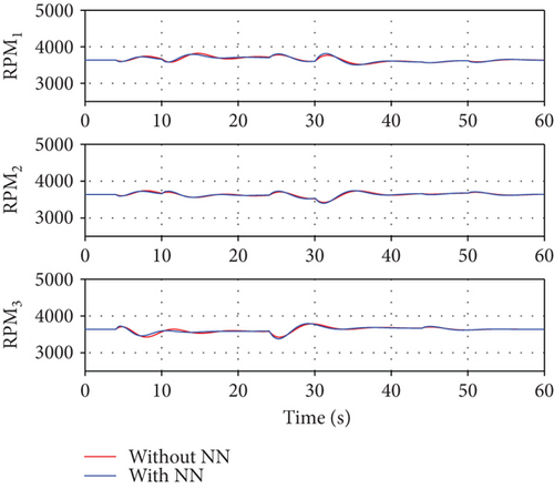
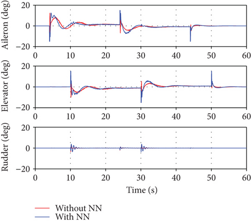
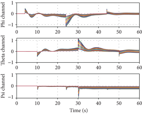
The first scenario assumed that the model uncertainty increases as the number of ducted-fan vehicles increases. It is assumed that 0 to 30% model uncertainty is generated in real time when two modules are added to the existing module. A simulation was performed to verify the control performance according to the application of the neural network. Figure 8 shows a relatively large overshoot and a slow follow-up when the neural network was not applied because the PD controller alone cannot compensate for the model error. On the contrary, each attitude response followed the command relatively quickly when the neural network was applied. However, as shown in Figures 9 and 10, the control input was excessively generated when the neural network was considered. The control allocation problem was not considered separately in this study. Hence, the control surfaces of the three modules moved in the same angle and direction. Each control surface deflection response was illustrated in a common graph. Meanwhile, the RPM control inputs showed different values to make the thrust difference by the center of the gravity. Figure 11 shows the weight of each channel when the neural network was applied. The weight change amount becomes large at the time of the command change, such that a deficient control input is generated.
4.2. Scenario 2
The second scenario presented a situation where the OFA consisting of three modules performed path control to combine with the other arrays in a strong disturbance environment. The attitude controller of the inner loop was generally classified according to whether the neural network was applied.
The outer loop for the path control adopted the PID controller. The disturbance was also assumed to be a uniform wind of 1.5 m/s along the x-axis of the body-fixed coordinate. As a result, the path control was not possible when the NN was not considered, as shown in Figure 12.
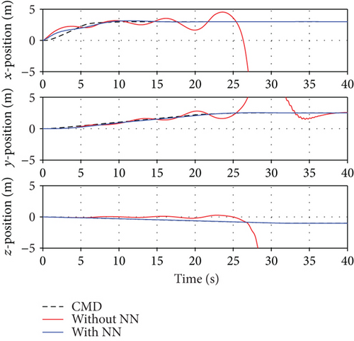
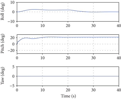
However, when the neural network controller is applied, it is observed that the position command is slightly slower but follows normally. Figure 13 shows the changes in the attitude of the UAV when the path control is normally performed in Figure 12. Through this result, it is confirmed that the attitude control system applying the neural network guarantees stability of the UAV in a strong disturbance environment. Figures 14 and 15 represent the control inputs when the neural network controller is applied. The oscillation of the elevator control surface in Figure 15 is caused to control the pitch angle in order to secure stability of the UAV and to follow the x-axis position command under the strong disturbance. This oscillation is caused by the changes in the cross-sectional force component, induced velocity, and z-axis translational velocity depending on the RPM, as shown in (18). This implies that the simulation results presented in this paper are under marginally stable conditions in which the ducted-fan UAV can operate.
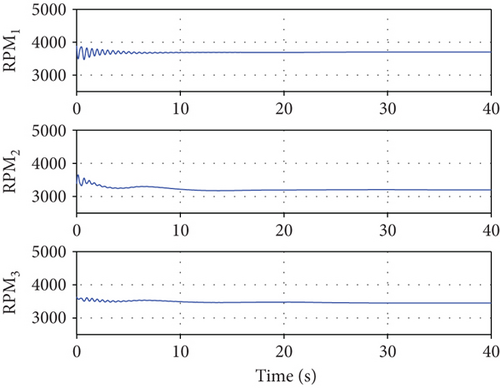
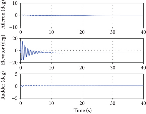
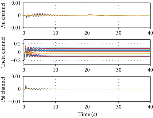
Since harsh disturbance is injected from the beginning of the simulation, such oscillation may be observed until the weights between the neural network layers are adjusted with sufficient samples of the system inputs/outputs. Furthermore, we considered the HS-5070MH servo motor as the control surface actuator that can deflect 60 deg for 0.12 sec at no load condition. Even if the full actuator performance cannot be guaranteed due to the aerodynamic load to the servo during the flight, there is still a sufficient margin to accommodate the maximum angular velocity (200 deg/s) observed in the simulation results. Figure 16 presents the weight update value of the neural network. The weight update value was confirmed to converge to a constant value after the position control is normally performed.
5. Conclusion
This study presented a concept of the organic flight array that can simultaneously perform various missions with a single ducted-fan vehicle through the assembling, separation, and cooperation modes. First, this study proposed a dynamic model for a single ducted-fan vehicle and defined the OFA dynamic model of the affine form, which is specified by the number of assembling modules. A control system was designed based on this through a dynamic model inversion and a PD controller. The adaptive controller based on the radial basis function neural network was also designed for the control system that can avoid model uncertainty or disturbance. Subsequently, the integrated simulation environment was constructed to verify the controller performance. The simulation results confirmed that the control performance was improved when the adaptive controller using the radial basis function neural network was considered in the case of model uncertainty or disturbance. Consequently, the control stability can be guaranteed when the neural network is used as an adaptive controller in a situation where the model uncertainty is large or the disturbance is strong.
Conflicts of Interest
The authors declare that they have no conflicts of interest.
Acknowledgments
This work is partly supported by the research project (no. 10062497) funded by the Ministry of Trade, Industry & Energy, Korean Government.


