Unsteady/Steady Hydromagnetic Convective Flow between Two Vertical Walls in the Presence of Variable Thermal Conductivity
Abstract
Unsteady as well as steady natural convection flow in a vertical channel in the presence of uniform magnetic field applied normal to the flow region and temperature dependent variable thermal conductivity is studied. The nonlinear partial differential equations governing the flow have been solved numerically using unconditionally stable and convergent semi-implicit finite difference scheme. For steady case, approximate solutions have been derived for velocity, temperature, skin friction, and the rate of heat transfer using perturbation series method. Results of the computations for velocity, temperature, skin friction, and the rate of heat transfer are presented graphically and discussed quantitatively for various parameters embedded in the problem. An excellent agreement was found during the numerical computations between the steady-state approximate solutions and unsteady numerical solutions at steady-state time. In addition, comparison with previously published work is performed and the results agree well.
1. Introduction
In recent years, the interest in the study of hydromagnetic flow in a channel region has been growing rapidly because of its extensive engineering applications. The experimental investigation of modern MHD flow in a laboratory was first carried out by [1]. This study provided the basic knowledge for the development of many MHD devices, such as MHD pumps, MHD generators, brakes, flow meters, plasma studies, and geothermal energy extraction. Unsteady free convection heat transfer with MHD effects in a channel region can be found in [2]. Unsteady hydromagnetic flows in rotating systems have been studied by [3–9]. An exact solution for unsteady hydromagnetic free convection flow with constant heat flux is to be found in [10]. All the above mentioned studies assumed the thermal conductivity of the fluid to be constant. However, it is known that the fluid physical properties may change significantly with temperature changes. To accurately predict the flow behavior and heat transfer rate, it is necessary to take into account the variation of thermal conductivity with temperature (see [11]). Thermal properties, particularly thermal conductivity and diffusivity, are essential materials parameters of bedrock controlling the heat transfer and temperature increases in the vicinity of repository. There has been considerable published work dealing with steady flow with variable thermal conductivity (see [12–18]). Recently (see [19]) studied steady MHD flow with variable thermal conductivity over an inclined radiative isothermal permeable surface.
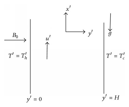
To the best of our knowledge, the problem of unsteady/steady hydromagnetic convective flow between two vertical walls heated symmetrically/asymmetrically in the presence of variable thermal conductivity has not been studied. The present paper is committed to study unsteady as well as steady natural convection flow of a viscous, incompressible fluid between two parallel vertical walls in the presence of transverse magnetic field and temperature dependent variable thermal conductivity when convection between the vertical parallel walls is set up by a change in the temperature of the walls compared to the fluid temperature.
2. Governing Equations
3. Approximate Solutions
4. Numerical Solutions
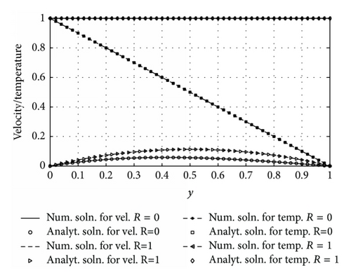
5. Results and Discussion
The numerical results are obtained by solving (14) using the method described in the previous section for various values of physical parameters to describe the physics of the problem. The nondimensional parameters that govern the flow are the Prandtl number (Pr), magnetic parameter (M), variable thermal conductivity parameter (λ), and buoyancy force distribution parameter (R). The value of Prandtl number (Pr) is taken as 1.0, which corresponds to electrolyte solution (see [22, 23]). Results obtained are presented graphically for velocity, temperature, skin friction, and Nusselt number for various flow parameters.
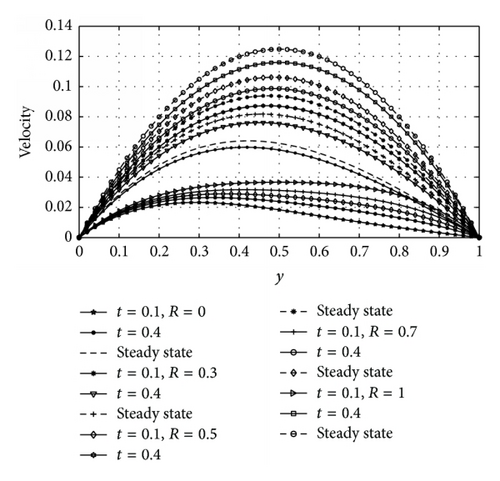
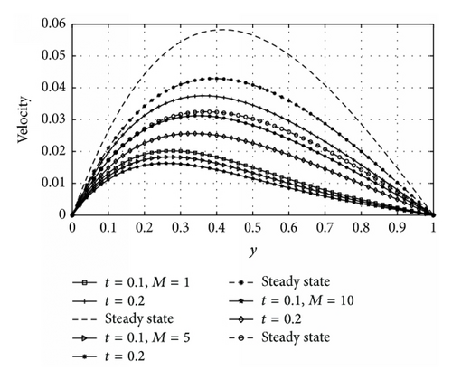
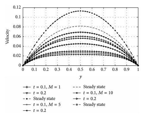
Figures 5 and 6 illustrate the velocity profiles of the fluid for different values of magnetic parameter (M) and nondimensional time (t) for asymmetric and symmetric case, respectively (i.e., R = 0 and R = 1). From Figure 5 it is observed that velocity of the fluid is maximum near the heated wall (y = 0) and then gradually decreases as it moves towards the cooled wall (y = 1). It is clear from Figure 6 that symmetric flow about occurs between the walls for all considered values of M and the nature of the figures is parabolic. In both Figures 5 and 6 it is noted that increasing M decreases the velocity of the flow throughout the channel walls. The physical explanation of this behavior is that the presence of magnetic field produces a resistivity force (Lorentz force) similar to the drag force which retard the velocity.
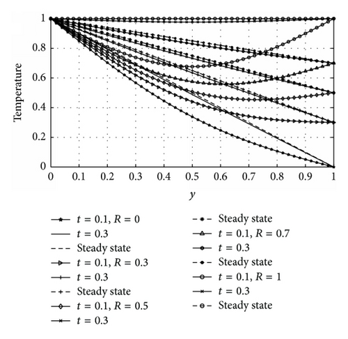
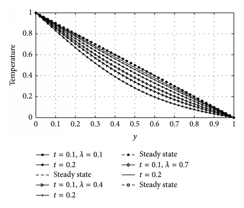
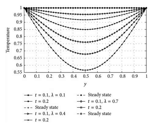
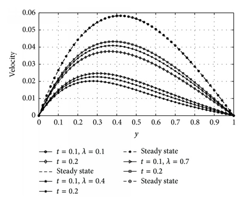
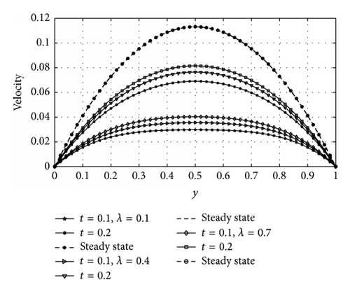
Figures 7 and 8, respectively, show the response of the fluid temperature to variation in the variable thermal conductivity parameter (λ) and time (t) for asymmetric and symmetric case. The effect of variable thermal conductivity (λ) and time (t) on velocity profiles for asymmetric and symmetric case is shown in Figures 9 and 10, respectively. From Figures 7 to 10, it is observed that both temperature and velocity of the fluid increase with increasing λ and t until a steady-state condition is attained. This is physically true, since the relation indicates that mounting values of λ increase the temperature difference between outside the plate and outside the boundary layer. As a result, heat is transferred rapidly from plate to fluid within the boundary layer. That is why both velocity and temperature profiles enlarge due to growing λ. It means that the velocity and the thermal boundary layer thickness rise for larger λ. From Figure 9, it is also seen that velocity of the fluid is maximum near the heated wall (y = 0) and then progressively decreases as it moves towards the cooled wall (y = 1). It is clear from Figures 8 and 10 that symmetric flow about occurs between the walls for all considered values of λ and t until a steady-state condition is achieved.
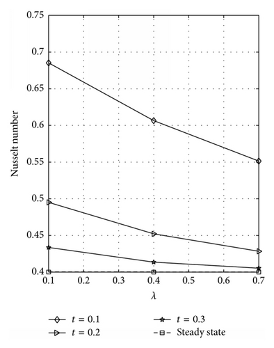
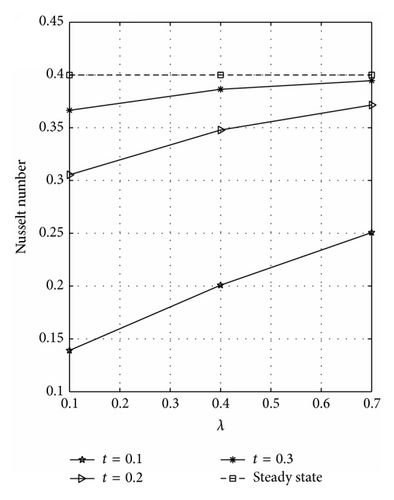
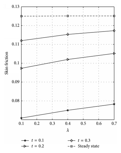
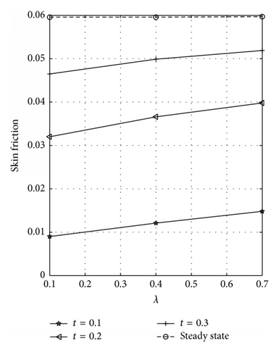
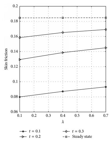
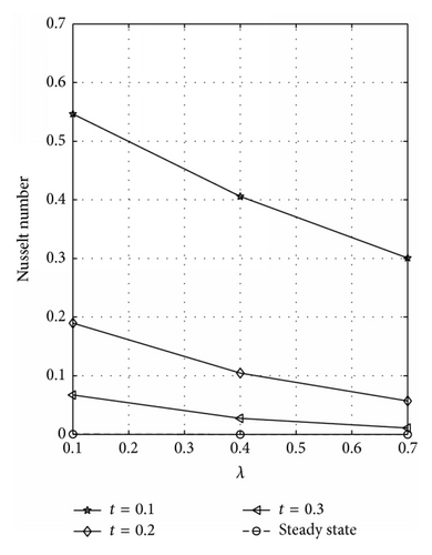
The rate of heat transfer (Nusselt number) dependence on λ is illustrated in Figure 11 for symmetric case. Figures 11(a) and 11(b) represent the rate of heat transfer at the walls y = 0 and y = 1, respectively. Figure 11(b) reveals that the rate of heat transfer increases as λ and t increase until a steady-state condition is reached. A reverse effect is observed at the plate y = 0; see Figure 11(a). The wall shear stress (skin friction) dependence on λ for varying values of t is illustrated in Figures 12(a) and 12(b) for symmetric case at the plates y = 0 and y = 1, respectively. From these figures, it is seen that skin friction increases with increase in λ and t. The skin friction and Nusselt number dependence on λ for varying values of t is displayed in Figures 13(a) and 13(b), respectively, at the plate y = 0 for asymmetric case. Figure 13(a) reflected that skin friction increases as λ and t increase until a steady-state condition is attained. Figure 13(b) reveals that Nusselt number decreases with increasing λ and t. It should be noted that the numerical values of skin friction at the plates y = 0 and y = 1 are the same for R = 1 because a symmetric flow occurs for this case. Also, the Nusselt number at the plates y = 0 and y = 1 is the same for R = 1.
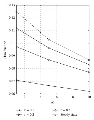
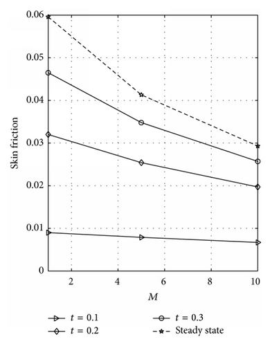
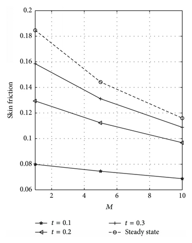
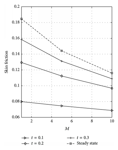
The skin friction dependence on M for varying values of t at the plates y = 0 and y = 1 is displayed in Figures 14(a) and 14(b), respectively, for R = 0. These figures reflected that skin friction decreases as M and t increase. Figures 15(a) and 15(b) are plotted to see the effects of M on the skin friction at the plates y = 0 and y = 1 for R = 1. From these figures, it is observed that skin friction decreases as M and t increase. Further, it is noted that Figures 15(a) and 15(b) are exactly the same. This is because a symmetric flow occurs for this case; that is, R = 1.
6. Conclusion
The problem of unsteady as well as steady hydromagnetic natural convection flow of a viscous, incompressible, and electrically conducting fluid between two vertical walls having asymmetric/symmetric temperatures on the walls in the presence of variable thermal conductivity and uniform applied magnetic field has been studied by obtaining approximated and numerical solutions of the governing equations, using perturbation series method and semi-implicit finite difference scheme. It is found that the fluid velocity and temperature increase with the increasing of variable thermal conductivity and nondimensional time for both asymmetric and symmetric heating, while magnetic parameter retards the motion of the fluid.
Conflict of Interests
The authors declare that there is no conflict of interests regarding the publication of this paper.


