Experimental Investigation and Multiobjective Optimization of Turning Duplex Stainless Steels
Abstract
This paper addresses experimental investigations of turning EN 1.4462 and EN 1.4410 duplex stainless steel grades with multilayer coated carbide inserts. Single-point wet and dry longitudinal turning tests of cylindrical bars are conducted; cutting forces, effective cutting powers, and tool wear are measured. The parametric influences of cutting speed, feed rate, and process conditions on the cutting performances such as resultant cutting force, specific effective cutting power, and flank wear are analyzed and proper conclusions are drawn. Nature-inspired metaheuristic bat algorithm is employed to handle the multiobjective optimization of the conflicting performances. Finally, the optimum cutting condition for each process condition can be selected from calculated Pareto optimal fronts by the user according to the planning requirements.
1. Introduction
Duplex stainless steels (DSSs) can be defined as a family of stainless steels whose structures are approximately 50% austenite and 50% ferrite, and its physical properties are a combination of the ferritic and the austenitic grades. In addition to their relatively low cost, they combine the best attributes of both austenitic and ferritic stainless steels which provide high strength and ductility with good resistance to corrosion (including stress corrosion cracking). Therefore, they are most commonly used when a combination of high mechanical strength and high corrosion resistance is required and are increasingly seen as an attractive alternative to the conventional stainless steels. However, owing to their high tensile and yield strength (roughly twice the yield strength of their counterpart austenitic grades, see Table 1), high work hardening rate, low thermal conductivity, high fracture toughness, strong tendency to form the built-up edge (BUE), and relatively high austenite and nitrogen content, modern duplex stainless steels are regarded as poorly machinable materials [1].
| Chemical composition %weight | EN 1.4462 | EN 1.4410 |
|---|---|---|
| C | 0.018 | 0.015 |
| Cr | 22.42 | 24.92 |
| Ni | 5.44 | 6.91 |
| Mo | 3.12 | 4.06 |
| Mn | 0.84 | 0.75 |
| Si | 0.37 | 0.25 |
| N | 0.18 | 0.3 |
| P | 0.025 | 0.021 |
| S | 0.0033 | 0.0007 |
| Mechanical properties | ||
| Yield strength (MPa) | 514 | 579 |
| Tensile (MPa) | 737 | 826 |
| Hardness (BHN) | 212 | 236 |
| Elongation (%) | 41 | 40 |
Over the past several years, few researchers have investigated the machining of duplex stainless steels. For instance, Bordinassi et al. studied the main effects of the turning in the superficial integrity of the duplex stainless steel ASTM A890-Gr6A. Their findings have shown that the smaller feed rate, smaller cutting speed, and the greater cutting depth provided the smaller values for the tensile residual stress, the smaller surface roughness, and the greater microhardness [2]. Królczyk et al. examined the influence of cutting parameters on surface roughness after DSS turning process. Their results have clearly showed that the feed rate was the main influencing factor on the surface roughness [3]. Królczyk et al. determined the coated carbide tool life and drew the tool wear curve when machining DSS. Their results have confirmed no effect of cutting speed and cooling on metallographic structure and designated the optimum cutting speed between 130 and 150 m/min and [4]. Nomani et al. have conducted machinability tests on duplex alloys SAF 2205 and SAF 2507, while employing austenite stainless steel 316L as a benchmark during drilling. Both duplex alloys displayed poorer machinability responses, with 2507 being worst [5]. Oliveira Jr. et al. have studied the turning operation of SAF 2507 and its influence on the alloy’s corrosion resistance in practical applications. Their results have indicated that turning with PVD-coated inserts under high-pressure cooling resulted in long tool lives, good workpiece roughness, and high corrosion resistance of the material after machining. The most frequent wear mechanism found during the tests was notch wear, while the main tool wear mechanism was attrition [6]. Philip Selvaraj et al. have optimized dry turning parameters of two different grades of nitrogen alloyed duplex stainless steel by using Taguchi method. Their results revealed that the feed rate is the most significant parameter influencing the surface roughness and cutting force. On the other hand, the cutting speed was identified as the most significant parameter influencing the tool wear [7].
In this paper, multiobjective bat algorithm (MOBA) is applied to optimize the conflicting turning performances such as resultant cutting force, specific effective cutting power, and maximum flank wear. The algorithm suggests sets of optimum solutions for the parameter setting of DSS turning process. The models of conflicting performances were obtained from experimental data. The rest of this paper is organized as follows. The description of MOBA is introduced in Section 2. Discussions of the obtained experimental results are presented in Section 3. Modeling of performance characteristics is described in Section 4. Results of MOBA are shown in Section 5 and some conclusions are given in Section 6.
2. Multiobjective Bat Algorithm (MOBA)
- (a)
All bats use echolocation to sense distance, and they also “know” the difference between food/prey and background barriers in some magical way.
- (b)
Bats fly randomly with velocity vi at position xi with a frequency φmin, varying wavelength, and loudness A0 to search for prey. They can automatically adjust the wavelength (or frequency) of their emitted pulses and adjust the rate of pulse emission r ∈ [0,1], depending on the proximity of their target.
- (c)
Although the loudness can vary in many ways, we assume that the loudness varies from a large (positive) A0 to a minimum constant value Amin.
-
Algorithm 1: Multiobjective bat algorithm (MOBA) [10].
-
Objective functions f1(x), …, fK(x), x =
-
Initialize the bat population xi (i = 1, 2, …, n) and vi
-
for j = 1 to N (points on Pareto fronts)
-
while (t < Max number of iterations)
-
Generate new solutions and update by (1)
-
if (rand > ri)
-
Random walk around a selected best solution
-
end if
-
Generate a new solution by flying randomly
-
if (rand < Ai & f(xi) < f(x*))
-
Accept the new solutions,
-
and increase ri& reduce Ai
-
end if
-
Rank the bats and find the current best x*
-
end while
-
Record x* as a non-dominated solution
-
end
-
Postprocess results and visualization
2.1. Pareto Optimality
3. Materials and Methods
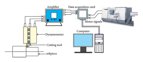
Full-factorial cutting tests are carried out on a CNC lathe (CTX 420 Linear V5) with maximum drive power 25 kW and a speed range of 35–7000 rpm. The workpiece materials for turning tests were standard DSS EN 1.4462 and super DSS EN 1.4410. Their chemical compositions and mechanical properties are given in Table 1.
The cutting tools used in the tests were made by Sandvik Coromant AB, Sweden. The solid carbide inserts were of type CNMG 120408-MM 2025. The coating consists of 5.5 μm CVD TiCN-Al2O3-TiN layers on a substrate which features excellent resistance to both mechanical and thermal shock. The triple coating consists of a 2.5 µm thick TiCN at the bottom followed by a 2 µm multilayer TiN/Al2O3 at the middle and finally a thin (~1 µm) outer coating of TiN on top. The inserts were mounted on a right hand style PCLNL-2525M-12 ISO type tool holder with tool geometry as follows: including angle = 80°, back rake angle = −6°, clearance angle = 5°, approach angle = 95°, and cutting edge radius ≈ 40 μm. The cutting and process conditions are given in Table 2. It has been designed to study the effects of the workpiece materials, process, and cutting conditions on the constants in Kienzle’s cutting force model.
| Cutting speed, m/min | 100, 180 |
| Feed rate, mm/rev | 0.15, 0.2, 0.25, 0.3, 0.35, 0.4 |
| Cutting depth, mm | 1 |
| Process condition | Dry, wet |
4. Results and Discussion
4.1. Specific Cutting Pressure
- (1)
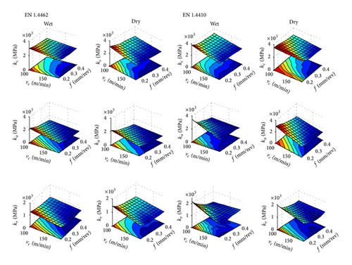
no drastic difference between the cutting pressures of dry and wet conditions was observed. However, overall wet machining shows an improvement in the machining performance through lower cutting pressures;
- (2)
specific cutting pressures when machining EN 1.4462 DSS were seen lower than the specific cutting pressures when machining EN 1.4410. Therefore, it can be predicted that the machinability index EN 1.4410 will be smaller than the machinability index of EN 1.4462;
- (3)
the cutting pressures generally showed a decreasing trend with increasing cutting speed and feed rate (see Figure 2). As it can be seen in this figure, the maximum cutting pressures occur at low cutting speeds and low feed rates. Thus, in order to achieve low cutting pressures, machining process should be done in high cutting speeds and high feed rates;
- (4)
modified Kienzle formula can be applied to evaluate the parametric effects of cutting conditions on the cutting forces as follows:
() -
where F represents the described cutting and resultant forces, k1.1 is the specific cutting pressure for 1 mm2 cross-sectional area of the cut, and a and b are constants. The model fitting has employed the least square method. Summary of models coefficients is listed in Table 3.
| Model | Proc. cond. | EN 1.4462 | EN 1.4410 | ||||
|---|---|---|---|---|---|---|---|
| k1.1 | a | b | k1.1 | a | b | ||
| Fc | Dry | 2367 | −0.28 | 0.1 | 2920 | −0.29 | 0.08 |
| Wet | 2215 | −0.26 | 0.13 | 2471 | −0.26 | 0.19 | |
| Ff | Dry | 852 | −0.48 | 0.47 | 1182 | −0.41 | 0.47 |
| Wet | 737 | −0.49 | 0.53 | 1126 | −0.64 | 0.5 | |
| Fr | Dry | 741 | −0.27 | 0.23 | 921 | −0.22 | 0.32 |
| Wet | 899 | −0.46 | 0.18 | 908 | −0.23 | 0.3 | |
| R | Dry | 2550 | −0.32 | 0.2 | 3145 | −0.31 | 0.21 |
| Wet | 2431 | −0.32 | 0.22 | 2811 | −0.35 | 0.28 | |
| Proc. cond. | EN 1.4462 | EN 1.4410 | ||||||
|---|---|---|---|---|---|---|---|---|
| R2 | F-value | P value | R2 | F-value | P value | |||
| Dry | 0.99 | 0.99 | 8430 | 7.8E − 16 | 0.99 | 0.99 | 5310 | 6.25E − 15 |
| Wet | 0.99 | 0.98 | 4010 | 2.2E − 14 | 0.99 | 0.99 | 7900 | 1.05E − 15 |
| Dry | 0.96 | 0.95 | 1660 | 1.2E − 12 | 0.84 | 0.80 | 350 | 1.24E − 09 |
| Wet | 0.94 | 0.92 | 1130 | 6.6E − 12 | 0.95 | 0.93 | 949 | 1.43E − 11 |
| Dry | 0.97 | 0.96 | 1720 | 9.9E − 13 | 0.73 | 0.67 | 159 | 4.14E − 08 |
| Wet | 0.96 | 0.95 | 1060 | 8.8E − 12 | 0.88 | 0.85 | 457 | 3.76E − 10 |
| Dry | 0.98 | 0.98 | 3870 | 2.6E − 14 | 0.96 | 0.95 | 1120 | 6.73E − 12 |
| Wet | 0.98 | 0.97 | 2250 | 3E − 13 | 0.98 | 0.97 | 2850 | 1.02E − 13 |
4.2. Specific Effective Cutting Power (Ps)
- (1)
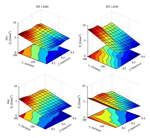
Specific effective cutting power is inversely proportional to the cutting speed and feed rate.
- (2)
Compared to the dry cutting, the wet cutting of EN 1.4462 and EN 1.4410 has shown lower values of Ps by 10.82% and 18.81%, respectively. This is mainly attributed to the lower cutting forces in wet cutting. Therefore, the advantage of employing wet cutting when machining DSSs overtakes its disadvantage of being more energy consumable due to the operation of the coolant pump.
- (3)
Average Ps when machining EN 1.4410 is 12.3% higher than the average Ps when machining EN 1.4462. This result is expected as the latter has inferior mechanical properties and higher percentage of chip breaking constituents such as sulfur and phosphorus (see Table 1).
- (4)
The effect of the process parameters on the Ps results can be modelled using the nonlinear model:
() -
where C1–3 are the model coefficients. The values of model coefficients and the check of adequacy of the models for each turning case are shown in Table 5. It can be seen from this table that the R2 values are high and close to 1, which are usually desirable. The large model F-values and small mode P values imply that the models are significant. Therefore, results from the statistical analyses indicate that the developed mathematical models can be successfully applied for predicting the Ps.
- (5)
The mean specific cutting pressure can be estimated by the equation:
() -
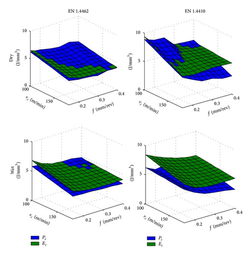
when cutting EN 1.4462 and EN 1.4410 were found to be 79.7% and 60.72% higher than corresponding Ps values (see Figure 4).
- (6)
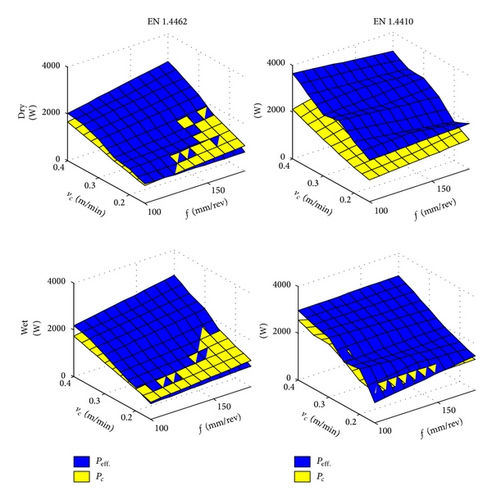
The comparison between the effective cutting power (Peff.) and the overall consumed cutting power (Pc) (see Figure 5) calculated by (11) has revealed that the average Peff. is 8.965% and 33.3195% higher than average Pc for cutting both EN 1.4462 and EN 1.4410, respectively. Results have also showed that the average Pc in wet cutting EN 1.4462 and EN 1.4410 were 2.9931% and 8.27% lower than the corresponding dry cutting:
()
| Coeff. | EN 1.4462 | EN 1.4410 | ||
|---|---|---|---|---|
| Dry | Wet | Dry | Wet | |
| C1 | 4.859 | 4.217 | 4.183 | 3.329 |
| C2 | −0.595 | −0.631 | −1.055 | −0.445 |
| C3 | 1.128 | 1.163 | 1.421 | 1.360 |
| Check of models adequacy | ||||
| R2 | 0.972 | 0.989 | 0.973 | 0.874 |
| 0.966 | 0.987 | 0.968 | 0.845 | |
| F-value | 3.35E + 03 | 7.70E + 03 | 1.06E + 03 | 6.29E + 04 |
| P value | 4.99E − 14 | 1.17E − 15 | 8.58E − 12 | 9.05E − 11 |
4.3. The Width of Maximum Flank Wear (VBmax )
- (1)
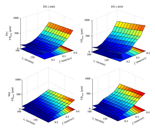
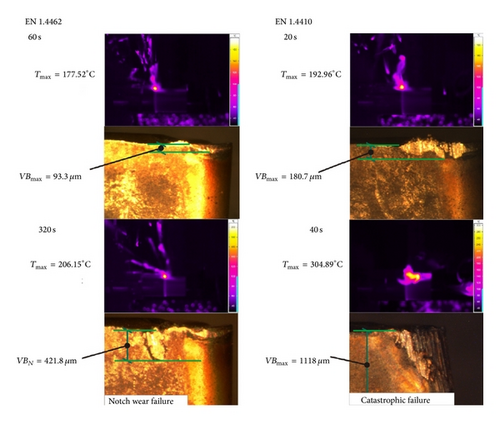
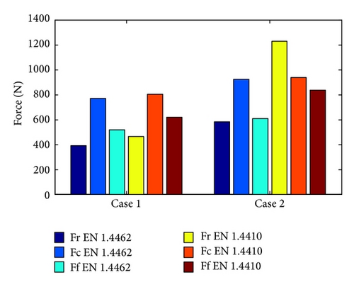
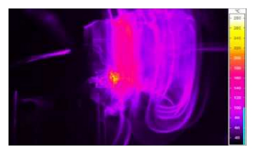
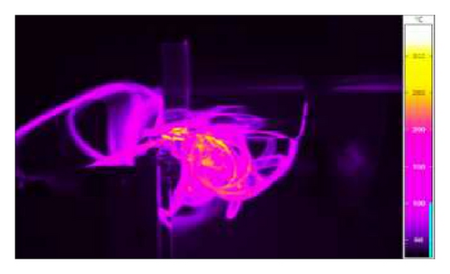
Based on the observations of tool wear behavior with respect to time during dry machining of DSSs, EN 1.4410 is considered more difficult-to-machine than EN 1.4462. For instance, machining EN 1.4410 at cutting speed value of 180 m/min and feed rate value of 0.35 mm/rev has resulted in significantly higher wear rate and thus shorter tool life, higher cutting temperature, higher cutting forces, and higher energy consumption than machining EN 1.4462 (see Figure 7). Figure 8 shows the average value of recorded cutting forces in dry conditions over 60 sec and 320 sec of machining EN 1.4462 and 20 sec and 40 sec of machining EN 1.4410.
-
An increasing trend in all cutting forces (main, feed, and radial) over time was observed. However, the largest percentage of cutting force increase was recorded in radial cutting force with 32.933% and 164.34% for machining EN 1.4462 and EN 1.4410, respectively. From this perspective, the most suitable parameter to monitor and correlate with progressive tool wear during machining is the radial cutting force component.
- (2)
The illustration of typical wear forms when machining DSSs are shown in Figure 9. The following can be seen.
- (a)
Severe adhesion between the chip and the rake face of the tool (BUE) was visible throughout the worn crater area. This is believed to be attributed to the high pressure and temperature encountered in machining ductile materials such as DSSs.
- (b)
Regardless of the adopted process conditions, chipping of the cutting edge at high feed rate was often observed, which has significantly contributed to acceleration of tool failure. Heavy load and impact when the tool entered and/or extracted the workpiece are considered to be the main reasons behind this phenomenon.
- (c)
The most dominant tool wear mode under low cutting speed conditions was the notch wear which was typically located near the depth of cut line. These notches act as stress and temperature raisers of the already high mechanical strength, strain hardening rate, fracture toughness, and low conductivity DSSs chips. Flaking occurrence because of the concentrated thermal load is more possible there. Ultimately, the combination of notch wear and flaking caused the cutting edge to fail abruptly.
- (d)
Another form of the main cutting edge damage is caused by the unfavorable chip morphology and chip flow (see Figure 10). Cutting DSSs at low cutting speed and feed rate has contributed to the formation of strong ribbon and snarled chips with dominant side-curl flow. The chips were entangled around the cutting tool, tool post, and workpiece and damaged to the cutting edge and the workpiece surface. The damage is often propagated along the main cutting edge of the tool with cutting time and had exceeded 5 mm length of damage in feed rate ranges of 0.15–0.20 mm/rev.
- (e)
In addition to the combined notching and flaking effects, nearly equal proportions of soft ferrite and hard austenite grains in the DSS structure make the cutting tool alternate cutting between soft and hard grains; this leads to an automatic tendency to initiate chatter in the cutting system and promote the catastrophic failure of the cutting tools.
- (a)
- (3)
To model VBmax, an empirical formula described by (8) is applied as follows:
() -
where λ1–3 are model constants. To check the adequacy of derived models, ANOVA for 95% confidence interval has been applied. Table 6 summarizes the values of coefficients and adequacy criterion. It can be seen that high correlation coefficients are existing between the experimental and predicted VBmax values and high model F-values, and low model P values (≪0.05) confirm the significance of the models.
| Coeff. | EN 1.4462 | EN 1.4410 | ||
|---|---|---|---|---|
| Dry | Wet | Dry | Wet | |
| λ1 | 4618.4 | 654.091 | 4473.3 | 2369.6 |
| λ2 | 0.29156 | 0.49853 | 0.50425 | 0.40716 |
| λ3 | −1.335 | −0.15483 | −1.236 | −0.8276 |
| Check of models adequacy | ||||
| R2 | 0.908 | 0.947 | 0.904 | 0.957 |
| 0.888 | 0.936 | 0.882 | 0.948 | |
| F-value | 1.17E + 02 | 4.55E + 02 | 1.10E + 02 | 3.15E + 02 |
| P value | 1.56E − 07 | 3.84E − 10 | 2.04E − 07 | 1.98E − 09 |


5. Multiobjective Optimization of Turning DSSs
- (1)
arithmetic average roughness (Ra)
() -
where rε is the tool nose radius (rε = 0.8 mm);
- (2)
cutting parameters lower and upper bounds:
()
| EN 1.4462 | EN 1.4410 | ||||||||||||||||||
|---|---|---|---|---|---|---|---|---|---|---|---|---|---|---|---|---|---|---|---|
| Dry | Wet | Dry | Wet | ||||||||||||||||
| vc | f | R | Ps | VBmax | vc | f | R | Ps | VBmax | vc | f | R | Ps | VBmax | vc | f | R | Ps | VBmax |
| (m/min) | (mm/rev) | (N) | (J/mm3) | (µm) | (m/min) | (mm/rev) | (N) | (J/mm3) | (µm) | (m/min) | (mm/rev) | (N) | (J/mm3) | (µm) | (m/min) | (mm/rev) | (N) | (J/mm3) | (µm) |
| 100.000 | 0.150 | 555.092 | 6.240 | 55.038 | 100.002 | 0.150 | 552.772 | 5.745 | 73.142 | 100.000 | 0.150 | 707.119 | 9.297 | 64.323 | 100.000 | 0.150 | 723.222 | 6.591 | 73.943 |
| 180.000 | 0.150 | 459.186 | 4.399 | 65.327 | 178.925 | 0.150 | 457.782 | 3.980 | 97.786 | 180.000 | 0.150 | 588.395 | 5.001 | 86.423 | 180.000 | 0.150 | 590.268 | 5.074 | 93.937 |
| 179.809 | 0.227 | 640.756 | 4.174 | 171.766 | 100.002 | 0.150 | 552.772 | 5.745 | 73.142 | 142.126 | 0.150 | 633.924 | 6.414 | 76.894 | 180.000 | 0.227 | 793.979 | 4.371 | 200.299 |
| 118.334 | 0.150 | 526.421 | 5.644 | 58.024 | 179.999 | 0.227 | 631.188 | 3.706 | 158.178 | 179.642 | 0.227 | 815.592 | 4.209 | 218.033 | 109.167 | 0.151 | 706.220 | 6.318 | 77.919 |
| 100.000 | 0.150 | 555.092 | 6.240 | 55.038 | 179.842 | 0.163 | 487.654 | 3.913 | 107.908 | 118.837 | 0.150 | 670.395 | 7.747 | 70.277 | 115.621 | 0.151 | 690.684 | 6.165 | 79.277 |
| 179.729 | 0.212 | 606.666 | 4.212 | 146.460 | 111.331 | 0.151 | 535.995 | 5.364 | 77.620 | 179.329 | 0.166 | 638.255 | 4.810 | 108.341 | 134.366 | 0.150 | 654.234 | 5.773 | 83.786 |
| 170.492 | 0.150 | 467.298 | 4.543 | 64.301 | 179.874 | 0.227 | 631.330 | 3.708 | 158.123 | 179.568 | 0.226 | 813.246 | 4.218 | 216.130 | 100.000 | 0.150 | 723.222 | 6.591 | 73.943 |
| 179.832 | 0.169 | 504.905 | 4.335 | 85.972 | 179.672 | 0.175 | 515.706 | 3.871 | 117.106 | 179.173 | 0.221 | 800.248 | 4.266 | 205.824 | 179.955 | 0.213 | 759.780 | 4.469 | 178.940 |
| 157.628 | 0.150 | 480.225 | 4.759 | 63.208 | 179.251 | 0.218 | 612.239 | 3.741 | 150.590 | 179.268 | 0.207 | 757.641 | 4.390 | 176.307 | 179.747 | 0.191 | 702.116 | 4.654 | 146.053 |
| 179.888 | 0.205 | 590.144 | 4.228 | 135.316 | 165.634 | 0.151 | 471.164 | 4.175 | 94.621 | 151.814 | 0.150 | 620.582 | 5.985 | 79.337 | 179.967 | 0.159 | 616.636 | 4.964 | 105.004 |
| 179.839 | 0.156 | 473.085 | 4.326 | 71.161 | 178.925 | 0.154 | 467.061 | 3.963 | 100.732 | 179.280 | 0.202 | 745.058 | 4.429 | 168.127 | 131.197 | 0.151 | 660.861 | 5.830 | 83.364 |
| 101.749 | 0.151 | 553.565 | 6.174 | 55.776 | 132.912 | 0.153 | 512.025 | 4.785 | 86.274 | 135.041 | 0.151 | 645.543 | 6.762 | 75.408 | 178.007 | 0.199 | 725.385 | 4.606 | 156.756 |
| 114.216 | 0.150 | 532.589 | 5.764 | 57.465 | 102.988 | 0.150 | 547.537 | 5.639 | 74.226 | 173.716 | 0.150 | 595.388 | 5.190 | 85.064 | 180.000 | 0.158 | 613.579 | 4.976 | 103.704 |
| 179.929 | 0.176 | 523.372 | 4.309 | 95.492 | 179.916 | 0.220 | 616.011 | 3.726 | 152.516 | 159.154 | 0.150 | 611.486 | 5.694 | 81.241 | 124.713 | 0.150 | 671.418 | 5.968 | 81.315 |
| 179.923 | 0.215 | 612.819 | 4.202 | 151.017 | 179.477 | 0.198 | 568.806 | 3.795 | 135.229 | 114.730 | 0.150 | 677.709 | 8.040 | 69.017 | 179.931 | 0.223 | 783.550 | 4.401 | 193.553 |
| 145.718 | 0.151 | 493.871 | 4.984 | 62.257 | 172.328 | 0.151 | 465.442 | 4.071 | 96.599 | 179.226 | 0.192 | 714.582 | 4.531 | 149.243 | 179.955 | 0.221 | 779.580 | 4.412 | 191.091 |
| 179.907 | 0.227 | 640.697 | 4.173 | 171.836 | 114.327 | 0.152 | 533.722 | 5.270 | 79.164 | 179.368 | 0.214 | 779.816 | 4.320 | 191.524 | 179.893 | 0.218 | 771.685 | 4.435 | 186.105 |
| 179.808 | 0.199 | 577.399 | 4.244 | 126.930 | 179.547 | 0.159 | 479.353 | 3.932 | 105.034 | 179.642 | 0.227 | 815.592 | 4.209 | 218.033 | 179.976 | 0.207 | 743.816 | 4.517 | 169.519 |
| 134.048 | 0.151 | 506.443 | 5.240 | 60.444 | 179.453 | 0.195 | 561.494 | 3.806 | 132.648 | 179.632 | 0.158 | 613.573 | 4.902 | 97.078 | 179.966 | 0.194 | 709.180 | 4.627 | 150.071 |
| 179.903 | 0.152 | 463.419 | 4.394 | 67.048 | 178.956 | 0.172 | 508.174 | 3.893 | 114.138 | 179.835 | 0.172 | 656.062 | 4.723 | 117.616 | 179.498 | 0.201 | 729.354 | 4.569 | 160.676 |
| 179.768 | 0.211 | 603.537 | 4.215 | 144.314 | 153.385 | 0.152 | 486.718 | 4.375 | 92.087 | 127.549 | 0.150 | 656.158 | 7.187 | 72.956 | 179.544 | 0.225 | 788.856 | 4.392 | 196.372 |
| 123.923 | 0.150 | 518.011 | 5.493 | 58.604 | 139.497 | 0.152 | 500.678 | 4.648 | 87.505 | 131.156 | 0.150 | 650.430 | 6.979 | 73.975 | 178.354 | 0.216 | 769.510 | 4.465 | 182.732 |
| 128.672 | 0.151 | 514.614 | 5.366 | 60.214 | 179.737 | 0.184 | 535.372 | 3.840 | 123.815 | 178.196 | 0.199 | 738.674 | 4.482 | 162.685 | 179.794 | 0.199 | 722.278 | 4.587 | 157.058 |
| 179.729 | 0.196 | 570.192 | 4.254 | 122.316 | 179.272 | 0.151 | 459.954 | 3.970 | 98.660 | 178.573 | 0.188 | 704.297 | 4.586 | 142.492 | 179.070 | 0.212 | 757.201 | 4.491 | 176.267 |
| 179.925 | 0.204 | 588.777 | 4.229 | 134.442 | 130.574 | 0.151 | 510.221 | 4.849 | 84.347 | 178.995 | 0.204 | 749.654 | 4.423 | 170.712 | 155.898 | 0.150 | 620.335 | 5.409 | 88.596 |
| 109.829 | 0.150 | 538.550 | 5.902 | 56.563 | 122.953 | 0.152 | 521.943 | 5.033 | 82.244 | 109.399 | 0.150 | 687.638 | 8.456 | 67.322 | 118.672 | 0.151 | 684.428 | 6.095 | 80.102 |
| 179.924 | 0.188 | 551.210 | 4.274 | 111.005 | 179.727 | 0.209 | 592.598 | 3.759 | 143.873 | 179.112 | 0.182 | 687.429 | 4.629 | 133.563 | 175.593 | 0.169 | 649.518 | 4.910 | 116.157 |
| 179.444 | 0.172 | 512.779 | 4.331 | 89.687 | 174.712 | 0.151 | 462.912 | 4.037 | 97.120 | 154.531 | 0.150 | 617.407 | 5.873 | 80.142 | 180.000 | 0.153 | 597.737 | 5.042 | 97.002 |
| 179.933 | 0.202 | 582.598 | 4.236 | 130.391 | 178.781 | 0.192 | 556.182 | 3.823 | 130.316 | 100.000 | 0.150 | 707.119 | 9.297 | 64.323 | 179.989 | 0.173 | 652.387 | 4.825 | 121.279 |
| 179.551 | 0.198 | 574.023 | 4.252 | 124.567 | 179.838 | 0.202 | 575.613 | 3.780 | 137.899 | 179.742 | 0.218 | 789.326 | 4.281 | 198.813 | 167.869 | 0.150 | 604.674 | 5.234 | 91.306 |
| 179.810 | 0.220 | 625.221 | 4.191 | 159.945 | 179.481 | 0.167 | 496.658 | 3.904 | 110.650 | 106.371 | 0.151 | 695.876 | 8.695 | 66.973 | 104.371 | 0.150 | 713.438 | 6.462 | 75.467 |
| 179.920 | 0.163 | 491.388 | 4.353 | 79.502 | 179.821 | 0.179 | 524.095 | 3.855 | 120.031 | 178.411 | 0.179 | 678.856 | 4.683 | 128.181 | 179.955 | 0.206 | 739.773 | 4.530 | 167.150 |
| 179.923 | 0.215 | 613.379 | 4.202 | 151.418 | 114.521 | 0.150 | 529.447 | 5.273 | 78.358 | 179.461 | 0.209 | 765.346 | 4.360 | 181.724 | 180.000 | 0.163 | 627.234 | 4.921 | 109.701 |
| 179.954 | 0.187 | 548.298 | 4.277 | 109.332 | 179.889 | 0.214 | 603.031 | 3.743 | 147.766 | 179.298 | 0.190 | 709.018 | 4.547 | 146.046 | 179.722 | 0.188 | 694.634 | 4.679 | 142.086 |
6. Conclusions
An experimental investigation on cutting of EN 1.4462 and EN 1.4410 duplex stainless steels was presented. A modelling technique based on the modified Kienzle’s equation was adopted to model the performances and ANOVA tests were performed to check the models adequacies. With the aid of three-dimensional surface plots, the effects of workpiece materials, process, and cutting conditions on the different cutting performances have been analysed and proper conclusion points have been drawn. Results of the early stages of this study have shown that the values of no-beneficial performances when cutting EN 1.4410 were generally higher than those of cutting EN 1.4462, and in comparison to the dry cutting, wet cutting has shown a general improvement in the machining performance.
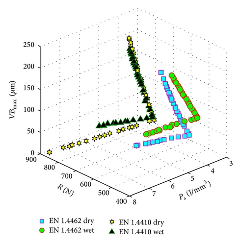
This paper also presented multiobjective optimization of machining duplex stainless steels based on the nature-inspired metaheuristic bat algorithm (MOBA). Three objectives are minimized simultaneously: resultant cutting force, specific effective cutting power, and maximum flank wear. Arithmetic average roughness has been included in the formulation of the optimization problem as a constraint. Results of optimization have shown that MOBA is very efficient and consistently converges to the sets of optimal solutions. It has provided Pareto frontiers of nondominated solution sets for optimum cutting conditions, providing decision makers with a resourceful and efficient means of achieving it. In addition to Pareto’s front graph, the paper is complemented with numerical outcomes.
Conflict of Interests
The authors declare that there is no conflict of interests regarding the publication of this paper.


