Sensitivity Analysis of the TRIGA IPR-R1 Reactor Models Using the MCNP Code
Abstract
In the process of verification and validation of code modelling, the sensitivity analysis including systematic variations in code input variables must be used to help identifying the relevant parameters necessary for a determined type of analysis. The aim of this work is to identify how much the code results are affected by two different types of the TRIGA IPR-R1 reactor modelling processes performed using the MCNP (Monte Carlo N-Particle Transport) code. The sensitivity analyses included small differences of the core and the rods dimensions and different levels of model detailing. Four models were simulated and neutronic parameters such as effective multiplication factor (keff), reactivity (ρ), and thermal and total neutron flux in central thimble in some different conditions of the reactor operation were analysed. The simulated models presented good agreement between them, as well as in comparison with available experimental data. In this way, the sensitivity analyses demonstrated that simulations of the TRIGA IPR-R1 reactor can be performed using any one of the four investigated MCNP models to obtain the referenced neutronic parameters.
1. Introduction
The TRIGA IPR-R1 research reactor, located at the Centro de Desenvolvimento da Tecnologia Nuclear (CDTN) sponsored by Comissão Nacional de Energia Nuclear (CNEN) in Belo Horizonte, Brazil, operates since 1960 and it has been an important source of experimental data used in the processes of verification and qualification of several modelling processes of neutronic and thermal-hydraulic codes. Furthermore, the Laboratory for Neutron Activation Analysis of CDTN has been responsible for 70% of the analytical demand using the k0 method of neutron activation analysis, established since 1995. Tests confirmed that the TRIGA IPR-RI reactor presented suitable characteristics to apply the method, mainly due to its stable and homogenous neutron fluxes. At that time, due to the symmetry of the core configuration and the rotary rack, no variations in neutron flux distribution in different channels were taken into account. The average thermal and epithermal fluxes were determined in the reactor rotating carousel facility (CF) [1, 2]. However, the reactor core configuration was changed in 2001 to enable a future power increase from 100 to 250 kW. This change consisted of four fuel rods added to the core, replacing the graphite dummy elements in the circular TRIGA core configuration [3]. In this configuration, the axial and radial neutron fluxes have not been measured and there are no experimental data about these parameters.
Previous studies evaluated the neutron flux in eleven irradiation channels of TRIGA comparing the estimated values by MCNP with experimental data [4–6]. The results presented good agreement when compared with experimental data.
Another previous work [7] investigated two modelling processes using MCNP code for the TRIGA IPR-R1 reactor. It presented some differences in the core elements dimensions according to technical documents used to perform such models. Moreover, one of them presented more geometrical detailing in relation to the other. Both models presented good agreement with respect to the experimental data and they were verified in relation to the criticality calculation and reactivity changes.
During the modelling processes, there is not a fixed rule to perform it and then a large responsibility is passed to the code user in order to develop an adequate model scheme and each code user can model the same system, with the same code, in different ways. Therefore, sensitivity analysis including systematic variations in code input variables or modelling parameters must be used to help identify the relevant parameters necessary for a determined type of analysis, that is, to determine how “sensitive” a model is considering changes in the parameters values or structure model.
Now, to complete the process of sensitivity analysis, reactivity data to different control rod positions were obtained and compared with experimental available data. Furthermore, thermal and total neutron flux in the central thimble were calculated to be used and compared with experimental data in future works.
2. Methodology
2.1. TRIGA IPR-R1 Configurations
- (i)
The active length of fuel element was discretized in 36 nodes.
- (ii)
The superior grid, inferior grid, and pneumatic tube were configured in this model.
- (iii)
Control rods guide tube is present.
- (iv)
The rotary rack groove is coated by aluminium layer.
- (v)
The samples of irradiation can be inserted in the rotary rack or in the central thimble or in the pneumatic tubes.
As described before, the differences between the models are in the geometry detailing. These models have the same materials composition obtained from [8] and they were configured according to the characteristics of TRIGA IPR-R1 [7]. In both models, the core was configured in the MCNP5 using a cylinder that contains water, fuel elements, radial reflectors, central tube, control rods, and neutron source. Each rod has a coordinate value. In these models, the rods were filled according to their individual characteristics. Around the core is the rotary rack with adequate groove to insert the samples to irradiation. The reactor was configured inside the pool where water surrounds the core and the rotary rack.
- (i)
Case 1—Model 1 and Dimension 1.
- (ii)
Case 2—Model 1 and Dimension 2.
- (iii)
Case 3—Model 2 and Dimension 1.
- (iv)
Case 4—Model 2 and Dimension 2.
In the simulations, Dimension 1 has the geometric values of previous studies [8, 9] and Dimension 2 presents the geometric values of the technical report [10]. Table 1 shows the core elements dimensions of the simulated models and information about criticality calculation simulations.
| Modified elements description | Dimension 1 (cm) | Dimension 2 (cm) | |
|---|---|---|---|
| Active core | Outer radius | 22.098 | 22.060 |
| Annular reflector | Inner radius | 22.730 | 23.050 |
| Outer radius | 53.140 | 53.500 | |
| Height | 53.950 | 56.000 | |
| Annular reflector cladding | Inner radius | 22.098 | 22.060 |
| Outer radius | 54.410 | 54.500 | |
| Height | 55.855 | 58.000 | |
| Rotary rack groove | Inner radius | 29.883 | 29.050 |
| Outer radius | 36.957 | 38.509 | |
| Graphite element | Graphite radius | 1.799 | 1.789 |
| Aluminium fuel element | Fuel radius | 1.790 | 1.780 |
| Cladding inner radius | 1.799 | 1.789 | |
| Stainless steel fuel element | Central zirconium radius | 0.286 | 0.318 |
| Cladding outer radius | 1.865 | 1.880 | |
| Control rods | Cladding inner radius | 1.060 | 0.965 |
| Cladding outer radius | 1.111 | 1.110 | |
| Information of criticality calculation | Dimensions 1 and 2 | ||
| kcode particles number | 100,000 | ||
| Simulated cycles number (skipped) | 515 (15) | ||
| Fission source | Punctual source at origin of system | ||
| System: OpenSUSE 12.1 | |||
| Total memory (RAM): 94.5 GB | |||
| Machine processor | Processor Intel (R) Xeon (R) CPU X5690 @ 3.47 | ||
| Speed: 1,596 MHz | |||
| Core number: 24 | |||
2.2. Evaluated Neutronic Parameters
To the sensitivity analyses, the neutronic parameters evaluated were the effective multiplication factor (keff), the reactivity (ρ), and the thermal and total neutron flux in central thimble as described in detail in the next subsections.
2.2.1. Effective Multiplication Factor (keff) and Reactivity
- (a)
all control rods withdrawn;
- (b)
individual and gradual insertion of shim rod;
- (c)
individual and gradual insertion of safety rod;
- (d)
individual and gradual insertion of regulating rod;
Experimental data with all control rods withdrawn can be obtained because TRIGA is the only nuclear reactor in this category that offers inherent safety. The safety of the reactor would be guaranteed even if the engineered features were bypassed and the control rods were rapidly removed. TRIGA is not ordinary light water reactor because much of its moderation of neutrons is due to the hydrogen that is mixed in with the fuel itself. Therefore, as the fuel temperature increases when the control rods are suddenly removed, the neutrons inside the hydrogen-containing fuel rod become faster than the neutrons outside in the cold water. These fast neutrons inside the fuel cause less fission and escape into the surrounding water. The end result is that the reactor automatically reduces the power in a few milliseconds [10, 11].
2.2.2. Neutron Flux into Central Thimble
- (a)
all control rods withdrawn;
- (b)
only the shim rod totally inserted into the core;
- (c)
only the safety rod totally inserted into the core;
- (d)
only the regulating rod totally inserted into the core.
3. Results
3.1. Reactivity Analysis
Table 2 presents the standard deviation (σST) and relative error (R) to the keff calculated by MCNP5 code. In addition, it shows the computation time (CT) for each case. According to [12], the values are reliable when the relative error R < 0.10. Table 2 shows that the relative error is around 0.011% and, therefore, the calculated keff values are acceptable. In addition, Table 2 shows that Cases 3 and 4 (configured with Model 2) present CT bigger than those for Cases 1 and 2 (configured with Model 1). This behaviour is due to Model 2 presenting more detailed geometry than Model 1. The MCNP code spends more time to follow particles in detailed geometries due to the increase of the number of surfaces and volumes. The code tracks particles through the geometry; it calculates the intersection of a track’s trajectory with each bounding surface and finds the minimum positive distance to an intersection. MCNP finds the correct cell that the particle will enter by checking the sense of the intersection point for each surface listed for the cell. When a complete match is found, MCNP has found the correct cell on the other side and the transport continues [12]. Therefore, a large number of surfaces will spend more computational time.
| Case type | Evaluated parameter | Control rod totally inserted | |||
|---|---|---|---|---|---|
| Shim | Safety | Regulating | No rods | ||
| Case 1 | keff | 0.99603 | 0.99741 | 1.01809 | 1.02236 |
| σST | 0.00011 | 0.00011 | 0.00011 | 0.00011 | |
| R (%) | 0.01104 | 0.01103 | 0.01080 | 0.01076 | |
| CT (min) | 36.14 | 35.55 | 35.73 | 36.20 | |
| Case 2 | keff | 0.98772 | 0.98914 | 1.01016 | 1.01411 |
| σST | 0.00011 | 0.00011 | 0.00012 | 0.00012 | |
| R (%) | 0.01114 | 0.01112 | 0.01188 | 0.01183 | |
| CT (min) | 35.07 | 35.52 | 35.78 | 35.81 | |
| Case 3 | keff | 0.99644 | 0.99805 | 1.01851 | 1.02300 |
| σST | 0.00010 | 0.00011 | 0.00011 | 0.00011 | |
| R (%) | 0.01004 | 0.01102 | 0.01080 | 0.01075 | |
| CT (min) | 89.84 | 87.56 | 88.03 | 89.06 | |
| Case 4 | keff | 0.98479 | 0.98627 | 1.00702 | 1.01126 |
| σST | 0.00011 | 0.00011 | 0.00011 | 0.00011 | |
| R (%) | 0.01117 | 0.01115 | 0.01092 | 0.01088 | |
| CT (min) | 86.94 | 88.38 | 88.57 | 88.43 | |
Table 3 presents the values of keff, ρ, Δkeff, and Δρ when the shim, safety, or regulating rod is totally inserted into core. This table shows these parameters to four studied cases and to experimental data (ED). The keff1 represents the effective multiplication factor to all control rods withdrawn and keff2 is the effective multiplication factor due to only one of the control rods (shim, safety, or regulating) inserted into the core.
| Case type | Control rod totally inserted | Evaluated parameter | |||||
|---|---|---|---|---|---|---|---|
| keff1 | keff2 | Δkeff (×10−2) | ρ1 (pcm) (×103) | ρ2 (pcm) (×103) | Δρ (pcm) (×103) | ||
| Case 1 | Shim | 1.02236 | 0.99603 | −2.63300 | 2.18710 | −0.39858 | −2.58568 |
| Safety | 0.99741 | −2.49500 | −0.25967 | −2.44677 | |||
| Regulating | 1.01809 | −0.42700 | 1.77686 | −0.41024 | |||
| No rods | 1.02236 | 0.00000 | 2.18710 | 0.00000 | |||
| Case 2 | Shim | 1.01411 | 0.98772 | −2.63900 | 1.39137 | −1.24327 | −2.63464 |
| Safety | 0.98914 | −2.49700 | −1.09792 | −2.48929 | |||
| Regulating | 1.01016 | −0.39500 | 1.00578 | −0.38559 | |||
| No rods | 1.01411 | 0.00000 | 1.39137 | 0.00000 | |||
| Case 3 | Shim | 1.02300 | 0.99644 | −2.65600 | 2.24829 | −0.35727 | −2.60556 |
| Safety | 0.99805 | −2.49500 | −0.19538 | −2.44367 | |||
| Regulating | 1.01851 | −0.44900 | 1.81736 | −0.43093 | |||
| No rods | 1.02300 | 0.00000 | 2.24829 | 0.00000 | |||
| Case 4 | Shim | 1.01126 | 0.98479 | −2.64700 | 1.11346 | −1.54449 | −2.65795 |
| Safety | 0.98627 | −2.49900 | −1.39211 | −2.50558 | |||
| Regulating | 1.00702 | −0.42400 | 0.69711 | −0.41636 | |||
| No rods | 1.01126 | 0.00000 | 1.11346 | 0.00000 | |||
| Experimental Data [8, 9] | Shim | 1.01859 | 0.99418 | −2.44100 | 1.82507 | −0.58541 | −2.41048 |
| Safety | 0.99615 | −2.24400 | −0.38649 | −2.21156 | |||
| Regulating | 1.01434 | −0.42500 | 1.41373 | −0.41134 | |||
| No rods | 1.01859 | 0.00000 | 1.82507 | 0.00000 | |||
The investigated cases have the same behaviour when the shim, the safety, or the regulating rod is inserted in the reactor core (see Table 3). In these cases, the insertion of shim rod induces the highest Δkeff, while the insertion of regulating rod causes the smallest Δkeff. In this way, the shim rod presents the highest Δρ while the regulating rod presents the lower value of Δρ. On the other hand, for the safety and shim rods the Δkeff and Δρ values are similar. The difference between the behaviours of such rods is due to their positions in the core. The regulating rod is located in the periphery of the core while the safety and shim rods are positioned near to the core centre. The simulated cases present the same behaviour of the experimental data.
| Inserted control rod | Case 1 | ED | Difference | |||
|---|---|---|---|---|---|---|
| keff | ρ | keff | ρ | keff | ρ | |
| Shim | 0.99603 | −0.00399 | 0.99418 | −0.00585 | 0.00185 | 0.00186 |
| Safety | 0.99741 | −0.00260 | 0.99615 | −0.00386 | 0.00126 | 0.00126 |
| Regulating | 1.01809 | 0.01777 | 1.01434 | 0.01414 | 0.00375 | 0.00363 |
| No rods | 1.02236 | 0.02187 | 1.01859 | 0.01825 | 0.00377 | 0.00362 |
| Inserted control rod | Case 2 | ED | Difference | |||
| keff | ρ | keff | ρ | keff | ρ | |
| Shim | 0.98772 | −0.01243 | 0.99418 | −0.00585 | −0.00646 | −0.00658 |
| Safety | 0.98914 | −0.01098 | 0.99615 | −0.00386 | −0.00701 | −0.00712 |
| Regulating | 1.01016 | 0.01006 | 1.01434 | 0.01414 | −0.00418 | −0.00408 |
| No rods | 1.01411 | 0.01391 | 1.01859 | 0.01825 | −0.00448 | −0.00434 |
| Inserted control rod | Case 3 | ED | Difference | |||
| keff | ρ | keff | ρ | keff | ρ | |
| Shim | 0.99644 | −0.00357 | 0.99418 | −0.00585 | 0.00226 | 0.00228 |
| Safety | 0.99805 | −0.00195 | 0.99615 | −0.00386 | 0.00190 | 0.00191 |
| Regulating | 1.01851 | 0.01817 | 1.01434 | 0.01414 | 0.00417 | 0.00403 |
| No rods | 1.02300 | 0.02248 | 1.01859 | 0.01825 | 0.00441 | 0.00423 |
| Inserted control rod | Case 4 | ED | Difference | |||
| keff | ρ | keff | ρ | keff | ρ | |
| Shim | 0.98479 | −0.01544 | 0.99418 | −0.00585 | −0.00939 | −0.00959 |
| Safety | 0.98627 | −0.01392 | 0.99615 | −0.00386 | −0.00988 | −0.01006 |
| Regulating | 1.00702 | 0.00697 | 1.01434 | 0.01414 | −0.00732 | −0.00717 |
| No rods | 1.01126 | 0.01113 | 1.01859 | 0.01825 | −0.00733 | −0.00712 |
Comparing Cases 1 and 2 (Model 1) or Cases 3 and 4 (Model 2), Cases 1 and 3 (Dimension 1) present the lowest value of the analysed difference. In comparison with the experimental data, Dimension 1 presents values of keff and ρ slightly overestimated while Dimension 2 presents values slightly underestimated.
As shown in Table 1, the fuel radius of aluminium element for Dimension 2 is smaller than for Dimension 1. Moreover, the central zirconium radius of stainless steel element in Dimension 2 is higher than in Dimension 1. These differences cause small decreasing of fissile material in the reactor core reducing the values of keff and ρ parameters. Furthermore, Dimension 1 presents outer radius of active core higher than Dimension 2. Then, the active core in Cases 1 and 3 presents more water volume than in Cases 2 and 4. As the water is a moderator material, its largest volume in Cases 1 and 3 causes probably an increase in the thermal fission. Consequently, Cases 1 and 3 presented keff values increased in comparison with Cases 2 and 4.
Although Cases 1 and 3 as well as Cases 2 and 4 have the same dimensions, Cases 3 and 4 have more detailed geometry (Model 2) which presents grid plates and control rods guide tube. In Cases 1 and 2 (Model 1), the volume of these elements is filled with water. Therefore, Model 1 presents water volume bigger than Model 2. As the water is a moderator material, Cases 1 and 2 (Model 1) have keff value bigger than Cases 3 and 4 (Model 3) (see Table 4).
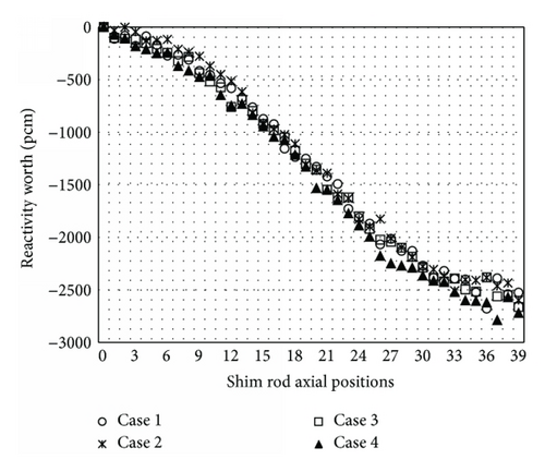
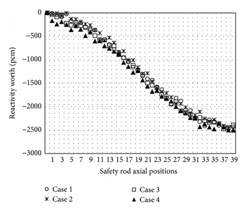
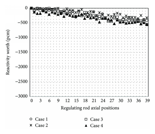
Figures from 1 up to 3 show the evolution of the Δρ for 39 axial positions of the shim, safety, and regulation control rods, respectively. In the figures, the zero position (“0”) represents total withdraw and the thirty-nine position (“39”) represents total insertion of control rods. As mentioned before, (3) was applied to calculate the control rods reactivity worth (Δρ) to each of the 39 axial positions where the relative error of Δρ is around 4.9 × 10⁻⁴. As it can be observed in the figures, the evolution of the Δρ presented the expected behaviour for all the simulated cases: as the control rods are inserted in the reactor core, the reactivity variations (Δρ) increase. In agreement with the values presented in the Table 3, the shim and safety rods produce bigger reactivity worth (Figures 1 and 2) than the regulating rod (Figure 3) due to its radial core position. According to the Figures 1 and 2, the shim and safety rods provide around 2600 pcm each, while the regulating rod (Figure 3) provides about 500 pcm Δρ total.
3.2. Neutron Flux Analysis in the Central Thimble
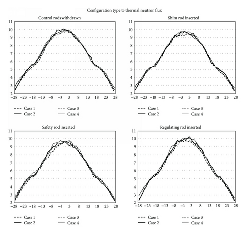
Figures 4 and 5 present thermal and total neutron fluxes, respectively, along the axial thimble positions for the four cases and for each case of control rod insertion. The ordinate axis represents the neutron flux values divided by 1012 and the abscissa axis represents the axial central thimble positions. As the central thimble was partitioned in 56 cylindrical cells in the model, the horizontal axis shows 56 positions from “–28” (bottom) up to “28” (top).
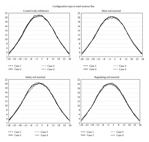
According to [12] the flux value is reliable when the relative error R < 0.10. In the simulated cases, the relative error of the estimated flux values is around 1%. Therefore, the calculated neutron flux values are statistically acceptable.
As it can be verified in Figures 4 and 5, the behaviour of the neutron flux distributions presents the typical “bell-shape.” For the simulated cases, there are some small differences in the flux values where the biggest difference is 7.5%.
As it was analyzed previously, the shim and the safety rods moving cause the biggest Δρ (see Table 3). Consequently, the insertion of such rods will produce the higher flux reduction. This behaviour was verified in the simulated cases (see Figures 4 and 5); in spite of the effect of this control rods insertion, the flux depression is very small. In addition, Table 5 presents the average total flux value in the middle of central thimble where the smallest flux values are of shim and safety rods inserted.
| Inserted control rod | Thermal neutron flux (×1012·cm−2·s−1) | |||
|---|---|---|---|---|
| Case 1 | Case 2 | Case 3 | Case 4 | |
| Shim | 9.2640 | 9.7634 | 9.6070 | 9.7285 |
| Safety | 9.5623 | 9.6109 | 9.6603 | 9.6336 |
| Regulating | 9.7181 | 10.0224 | 9.9171 | 9.9200 |
| No rods | 9.7271 | 10.0520 | 9.9273 | 9.9469 |
| Inserted control rod | Total neutron flux (×1012·cm−2·s−1) | |||
| Case 1 | Case 2 | Case 3 | Case 4 | |
| Shim | 19.3679 | 20.0651 | 20.1728 | 20.1664 |
| Safety | 19.8719 | 19.8786 | 20.0287 | 20.2220 |
| Regulating | 20.0979 | 20.5195 | 20.3159 | 20.7339 |
| No rods | 20.2836 | 20.7059 | 20.3656 | 20.9112 |
4. Conclusions
In this work, four cases of the TRIGA IPR-R1 reactor were analyzed using the MCNP5 code to estimate values of keff, ρ, Δkeff, Δρ and neutron flux in central thimble in some different conditions of the reactor operation. The simulated Models 2 and 3 present corrections in the geometry dimensions of some core elements where Model 3 includes more geometry details than Model 2. The aim was to identify how much the code results could be affected according to these differences in the models.
As the results demonstrated, the differences between the simulated models are small and therefore acceptable. In this way, the differences in the geometry dimensions detected in different reference works generated small variations in the evaluated neutronic parameters and the physical behaviour of these models is the same as all simulated models. The simulated models presented good agreement between them for the evaluated neutronic parameters and also when they considered experimental data. Therefore, the sensitivity analyses demonstrated that future works for the TRIGA IPR-R1 simulations can be performed using any of the four investigated models.
Conflict of Interests
The authors declare that there is no conflict of interests regarding the publication of this paper.
Acknowledgments
The authors are grateful to the Brazilian research funding agencies, CNEN (Brazil), CNPq (Brazil), CAPES (Brazil), and FAPEMIG (MG/Brazil), for the support.


