Exergoeconomic and Enviroeconomic Analysis of Photovoltaic Modules of Different Solar Cells
Abstract
The exergoeconomic and enviroeconomic analysis of semitransparent and opaque photovoltaic (PV) modules based on different kinds of solar cells are presented. Annual electricity and net present values have also been computed for the composite climatic conditions of New Delhi, India. Irrespective of the solar cell type, the semitransparent PV modules have shown higher net energy loss rate (Len) and net exergy loss rate (Lex) compared to the opaque ones. Among all types of solar modules, the one based on c-Si, exhibited the minimum Len and Lex. Compared to the opaque ones, the semitransparent PV modules have shown higher CO2 reduction giving higher environmental cost reduction per annum and the highest environmental cost reduction per annum was found for a-Si PV module.
1. Introduction
In this era of advanced technologies the demand of energy is increasing day by day. The sources of energy are very limited and are running out very rapidly. Emission of greenhouse gases from the fossil fuels is another major concern as it is causing the global warming [1]. Therefore, the renewable sources of energy are developed which have no harmful effects on our delicate environment. To reduce the impacts related to processing of any energy source the efficiency of energy plants should be improved and such studies are done by exergoeconomic and enviroeconomic analysis. The exergoeconomic analysis is basically the exergy analysis along with the cost analysis in order to access the performance of the energy systems [2]. It reveals the relative cost importance of each component and provides the ways to improve overall cost effectiveness [3, 4]. On the other hand, enviroeconomic analysis (also known as environmental cost analysis) identifies the options for reducing the environmental impact associated with the overall system [5].
Photovoltaic (PV) energy conversion is considered as one of the most promising renewable energy technology which has the potential to contribute significantly to a sustainable energy supply and to mitigate greenhouse gas emissions. PV systems are free from greenhouse gases emission. Badescu analyzed a heating system of an ecology building and found that a PV array can provide all the energy required to derive the heat pump compressor, if an appropriate electricity storage system is provided [6]. Ozgener and Hepbasli investigated the capital costs and thermodynamic losses in a greenhouse heating system with solar-assisted ground-source heat pump and found a correlation between the capital cost and exergy loss but no relation was established between capital cost and energy loss [7]. Caliskan et al. [8] performed the energy, exergy, environmental, exergoeconomic, enviroeconomic, and sustainability analyses of the novel air cooler considering the nine different dead state temperatures at constant environment temperature. They found the maximum exergetic cost rate of 0.0228 kWh/$-year at a dead state temperature of 37.77°C. According to the enviroeconomic analysis, the novel air cooler has CO2 emissions cost as 6.96$/year. Agrawal and Tiwari [9] have done the exergoeconomic analysis of a glazed PV thermal (PVT) module air collector and found that for energy saving point of view the glazed PVT module air collector is a better option compared to PV module. Prabhakant and Tiwari [10] have carried out an analysis of carbon credit earned by each district in India, for supplying minimum subsistence electricity to each family (energy security).
- (a)
clear days (blue sky);
- (b)
hazy days (fully);
- (c)
hazy and cloudy days (partially);
- (d)
cloudy days (fully).
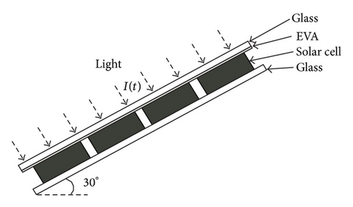
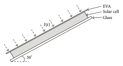
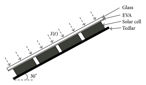
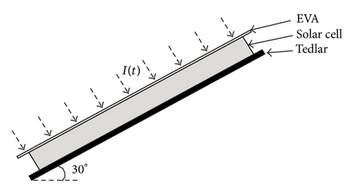
2. Modelling
- (i)
the heat conduction is in one direction;
- (ii)
the system is in quasi steady state;
- (iii)
the ohmic losses in solar cells and PV modules are negligible.
2.1. Energy Balance Equations
2.1.1. For Semitransparent c-Si
2.1.2. For Opaque c-Si PV Modules
2.1.3. For Thin Film (a-Si, CdTe, and CIGS) PV Modules
For semitransparent PV module, Ub is written as (effective τ > 0), whereas, for the opaque PV modules, Ub is given by (effective τ = 0).
2.2. Annual Electricity
2.3. Net Present Value (NPV)
2.4. Exergoeconomic and Enviroeconomic Analyses
2.4.1. Exergoeconomic Analysis
- (i)
For semitransparent c-Si PV module,
() - (ii)
For opaque c-Si PV module,
() - (iii)
For thin film PV modules (a-Si, CdTe, and CIGS):
()
2.4.2. Enviroeconomic Analysis
3. Methodology
The climatic data for the solar radiation I(t) on horizontal surface, ambient temperature (Ta), and the number of days for the weather conditions (a), (b), (c), and (d) for Delhi were obtained from the Indian Metrological Department (IMD), Delhi. The following methodology has been used for the exergoeconomic and enviroeconomic analysis of the PV module.
Step 1. The hourly solar radiation on the PV modules (75 Wp), at the 30° inclination from the horizontal, was calculated using the Liu and Jordan method [23, 24].
Step 2. The designed parameters, for all the PV modules, used for calculations have been tabulated in Table 1.
| Parameters | c-Si | a-Si | CdTe | CIGS |
|---|---|---|---|---|
| Am (m2) | 0.65 | 1.17 | 0.72 | 0.72 |
| αc | 0.9 | 0.85 | 0.8 | 0.8 |
| βc | 0.89 | 1 | 1 | 1 |
| β0 | 0.006 | 0.001 | 0.002 | 0.003 |
| ηm0 (%) | 14.20 | 6.40 | 10.40 | 10.42 |
| αT | 0.50 | |||
| τg | 0.95 | |||
| h0 (W/m2K) | 5.7 + 3.8v; v = 0.5 m/s | |||
| hi (W/m2K) | 2.8 + 3.0 v; v = 0.2 m/s | |||
| Lg (m) | 0.003 | |||
| Kg (W/m K) | 1.10 | |||
| LT (m) | 0.0005 | |||
| KT (W/m K) | 0.033 | |||
Step 3. For the known climatic conditions and designed parameters, the electrical efficiencies of the PV modules of c-Si and thin film (a-Si, CdTe, and CIGS) have been evaluated using (2), (3), and (5), respectively.
Step 4. The monthly electricity for clear days (condition (a)) has been evaluated using (6) and the same process was adopted to calculate the monthly electricity for other climatic conditions (b), (c), and (d). The total electricity for each month was obtained by adding the electricity generations in the climatic conditions (a), (b), (c), and (d) in that month.
Step 5. The annual electricity was calculated using (7).
Step 6. Net present value (NPV) has been calculated by (8). Operational and maintenance cost has been considered to be 10%, whereas salvage value has been taken as 5% of the present capital cost (P) of the modules. Interest rate i has been taken as 8%.
Step 7. Energy loss rate and exergy loss rate for c-Si semitransparent, c-Si opaque, and thin film PV module have been calculated by using ((10a), (10b), (10c), (10d), (10e), (10f))–(13).
4. Results and Discussion
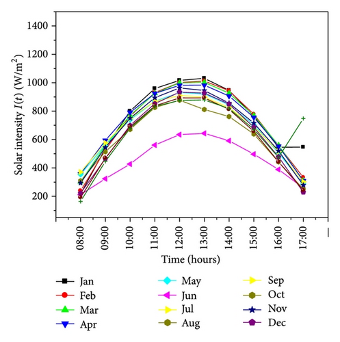
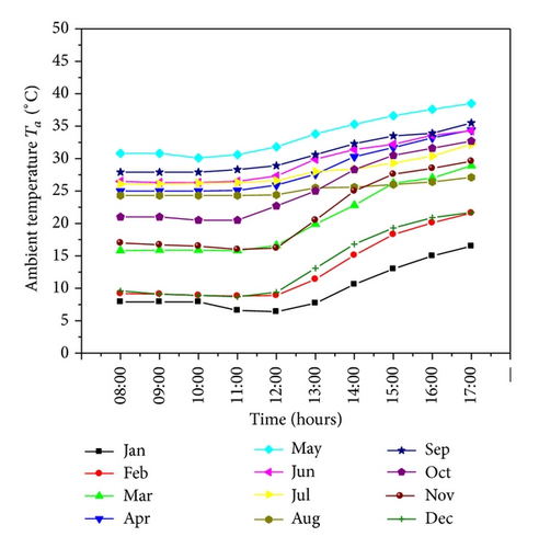
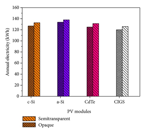
To solve the mathematical equations, a computer program MathCad 8 has been used. The hourly variations of I(t) at 30° inclination to the horizontal surface and ambient temperature (Ta) throughout the year are shown in Figures 2 and 3, respectively. The annual electricity for different semitransparent and opaque PV modules has been shown in Figure 4. For all the solar cell types, the semitransparent PV modules have shown higher annual electricity compared to the opaque ones. The maximum annual electricity is observed for a-Si to be 139 kWh for semitransparent and 133 kWh for opaque PV module. CIGS modules have shown the minimum annual electricity which is 125.9 and 120 kWh for semitransparent and opaque, respectively. Table 2 shows the net present capital value of each type of PV modules. c-Si has shown higher net present value (542.67$) than the other PV modules. It is because of high capital cost (212.96$) due to shortage of availability of the material and expensive manufacturing process. For all the PV modules, kWh/kWp values are also calculated to show the energy generated divided by the STC rating. Table 3 compares the energy rating values of all the semitransparent and opaque PV modules in kWh/kWp, electricity per installed power. Semitransparent PV modules have higher kWh/kWp (~4%) than that of the opaque ones while among all the PV modules a-Si exhibited highest kWh/kWp and CIGS has lowest kWh/kWp. The reason behind this is the higher annual electricity of a-Si PV module and lowest annual electricity of CIGS. Table 4 shows the Len and Lex for each PV module. Irrespective of solar cell type, the semitransparent PV module exhibited less Len and less Lex. The reason behind this is that the semitransparent PV modules have shown the higher efficiencies throughout the year compared to the opaque ones as in case of c-Si PV modules; the packing factor is considered to be 0.89. In that case the solar radiation falling on the nonpacking area is transmitted through the semitransparent module, whereas in case of opaque modules it is absorbed by the tedlar sheet. The absorption of solar radiation by tedlar sheet results into the increment in cell temperature, due to which the module efficiency decreases. But in case of thin film PV modules, the packing factor is considered to be 1 and there will be no nonpacking area. However, the higher efficiencies in semitransparent thin film PV modules compared to the opaque ones can be understood from their thin film property. Due to very low film thicknesses some of the heat of the incident radiation is transmitted through the back glass sheet but in case of opaque modules it was absorbed by the tedlar sheet. The absorption of solar heat by the tedlar sheet results in increments in the module temperature, due to which the module efficiency decreases. Therefore, semitransparent PV modules exhibited higher energy flux rate products and higher exergy flux rates as compared to the opaque ones that causes lower Len and Lex. Among all the PV technologies in both cases (semitransparent and opaque) a-Si has shown higher Len and Lex because it exhibited higher energy flux rate products and higher exergy flux rate products because of higher efficiency.
| PV technology | Total investment cost ($) | Capital cost (P) (a + b + c) ($) | Lifetime (n) (years) | Salvage value (S) ($.) (~5% of P) | Operational and maintenance cost ($) (~10% of P) | NPV ($) | ||
|---|---|---|---|---|---|---|---|---|
| Panel cost (a) | Stand cost (b) | Installation cost (c) | ||||||
| c-Si | 105 | 2.96 | 105 | 212.96 | 30 | 10.65 | 21.30 | 542.67 |
| a-Si | 60 | 3.70 | 105 | 168.70 | 20 | 8.43 | 16.87 | 405.47 |
| CdTe | 67.5 | 3.24 | 105 | 175.74 | 25 | 8.79 | 17.57 | 445.69 |
| CIGS | 60 | 3.24 | 105 | 168.24 | 20 | 8.41 | 16.82 | 542.67 |
| PV technology | Energy rating (kWh/kWp) | |
|---|---|---|
| Semi. | Opaque | |
| c-Si | 1770.29 | 1693.05 |
| a-Si | 1839.99 | 1783.37 |
| CdTe | 1750.05 | 1667.53 |
| CIGS | 1678.83 | 1600.65 |
| PV technology | Net energy loss rate (Len) (kWh) | Net exergy loss rate (Lex) (kWh) | ||
|---|---|---|---|---|
| Semi. | Opaque | Semi. | Opaque | |
| c-Si | 509.59 | 576.45 | 475.35 | 537.72 |
| a-Si | 1127 | 1129 | 1051 | 1054 |
| CdTe | 579.38 | 581.10 | 540.37 | 541.96 |
| CIGS | 582.90 | 584.50 | 543.79 | 545.20 |
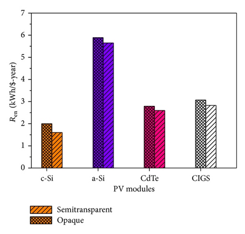
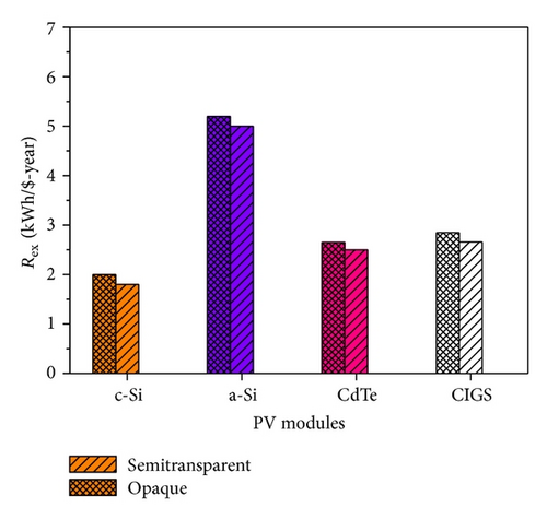
The ratios of thermodynamic loss rate to net present value (Ren) for all the PV modules are shown in Figure 5. It was observed that semitransparent PV module exhibited lower Ren than the opaque ones for all the PV technologies. Similarly Figure 6 shows Rex for all the PV modules and it was found to be lower for the semitransparent PV module. It is because of the lower energy and exergy flux rate products in semitransparent PV module. Table 5 shows the CO2 emission reduction per annum (tCO2e) and environmental cost reduction per annum ($) for all the PV modules. From Table 5 it is clear that, for all the PV technologies, the semitransparent modules have shown higher CO2 emission reduction per annum (tCO2e) giving higher environmental cost reduction per annum ($). The reason behind this is that the semitransparent PV module exhibited higher annual electricity. Among all the technologies it was found that a-Si PV module earns highest carbon credit and therefore higher maximum environmental cost reduction per annum compared to other PV modules. The reason behind this is the same as a-Si PV module having higher annual electricity.
| PV modules | CO2 emission reduction per annum (tCO2e) | Environmental cost reduction per annum ($) | ||
|---|---|---|---|---|
| Semi. | Opaque | Semi. | Opaque | |
| c-Si | 0.27 | 0.25 | 3.93 | 3.76 |
| a-Si | 0.28 | 0.27 | 4.10 | 3.96 |
| CdTe | 0.27 | 0.25 | 3.88 | 3.69 |
| CIGS | 0.26 | 0.24 | 3.72 | 3.6 |
5. Conclusions
- (i)
Semitransparent PV modules exhibited higher annual electricity and higher kWh/kWp compared to the opaque ones, whereas among all the PV modules a-Si has shown the maximum annual electricity generation and maximum kWh/kWp.
- (ii)
Semitransparent PV modules exhibited lower Len and Lex giving lower Ren and Rex, whereas among all the PV technologies, c-Si exhibited lowest energy rate and exergy rate.
- (iii)
Net CO2 mitigation (tCO2e) per annum was found to be maximum in semitransparent PV module giving higher environmental cost reduction per annum ($). Among all the technologies, a-Si PV module earns highest carbon credit and higher maximum environmental cost reduction per annum compared to other PV modules.
Therefore, as a whole for energy saving and impact on environment point of view, the semitransparent PV module is more beneficial than opaque ones.
Nomenclature
-
- Am:
-
- Area of module (m2)
-
- h0:
-
- Heat loss coefficient from the top (W/m2)
-
- hi:
-
- Heat loss coefficient from the bottom (W/m2)
-
- I(t):
-
- Incident solar intensity (W/m2)
-
- K:
-
- Thermal conductivity (W/mK)
-
- T:
-
- Temperature (K)
-
- UT:
-
- Overall top loss heat transfer coefficient from solar cell to ambient (W/m2K)
-
- Ub:
-
- Overall bottom loss heat transfer coefficient from solar cell to ambient (W/m2K)
-
- L:
-
- Length (m)
-
- R:
-
- Reflectivity
-
- v:
-
- Air velocity
-
- Len:
-
- Energy loss rate
-
- Lex:
-
- Exergy loss rate
-
- Ts:
-
- Solar temperature.
Subscripts
-
- a:
-
- Ambient
-
- c:
-
- Solar cell
-
- g:
-
- Glass
-
- m:
-
- Module
-
- T:
-
- Tedlar.
Greek Letters
-
- α:
-
- Absorption factor
-
- β0:
-
- Temperature coefficient of the material
-
- β:
-
- Packing factor
-
- η:
-
- Efficiency
-
- η0:
-
- Solar cell efficiency at standard test condition (STC)
-
- ηm0:
-
- PV module efficiency at standard test conditions (STC)
-
- τ:
-
- Transmitivity.
Conflict of Interests
The authors declare that there is no conflict of interests regarding the publication of this paper.
Acknowledgment
One of the authors (Ankita Gaur) is thankful to the Department of Science and Technology, New Delhi, India, for providing INSPIRE fellowship to pursue the present research work.


