Control of Variable Speed Variable Pitch Wind Turbine at Above and Below Rated Wind Speed
Abstract
The paper presents a nonlinear approach to wind turbine (WT) using two-mass model. The main aim of the controller in the WT is to maximize the energy output at varying wind speed. In this work, a combination of linear and nonlinear controllers is adapted to variable speed variable pitch wind turbines (VSVPWT) system. The major operating regions of the WT are below (region 2) and above rated (region 3) wind speed. In these regions, generator torque control (region 2) and pitch control (region 3) are used. The controllers in WT are tested for below and above rated wind speed for step and vertical wind speed profile. The performances of the controllers are analyzed with nonlinear FAST (Fatigue, Aerodynamics, Structures, and Turbulence) WT dynamic simulation. In this paper, two nonlinear controllers, that is, sliding mode control (SMC) and integral sliding mode control (ISMC), have been applied for region 2, whereas for pitch control in region 3 conventional PI control is used. In ISMC, the sliding manifold makes use of an integral action to show effective qualities of control in terms of the control level reduction and sliding mode switching control minimization.
1. Introduction
In recent years, wind energy is one of the major renewable energy sources because of environmental, social, and economic benefits. The major classification of wind turbines (WT) is fixed speed wind turbine (FSWT) and variable speed wind turbine (VSWT). Compared with FSWT, VSWT have many advantages such as improved energy capture, reduction in transient load, and better power conditioning [1]. For any kind of WT, control strategies play a major role on WT characteristics and transient load to the network [2]. In VSWT the operating regions are classified in to two major categories, that is, below and above rated wind speed. At below rated wind speed the main objective of the controller (i.e., torque control) is to optimize the wind energy capture by avoiding the transients in the turbine components especially in the drive train. At above rated wind speed the major objective of the controller (i.e., pitch control) is to maintain the rated power of the WT. For extracting the maximum power at below rated wind speed the WT rotor speed should operate at reference rotor speed which is derived from effective wind speed. In general wind speed is measured by the anemometer which is varying along the rotor shift area so it is difficult to get the mean wind speed by this measurement. Several literatures are addressing this issue by estimating the effective wind speed. But some other literatures assume that the effective wind speed is directly available [3, 4]. In [5] a combination of proportional integral (PI) and SMC is used to adjust the turbine rotor speed for extracting maximum power without estimating the wind speed. In [6] a PI based torque control is used to control the WT, where optimal gains are achieved by particle swarm optimization and fuzzy logic theory, without estimating the wind speed. Estimation of effective wind speed by an inversion of static aerodynamic model with known pitch angle is discussed in [7]. Nonlinear static and dynamic state feedback linearization control is addressed in [8, 9] where both the single- and two-mass model are taken into consideration and the wind speed is estimated by using Newton Raphson (NR). To accommodate the parameter uncertainty and robustness a higher order sliding mode controller is proposed in [10], which ensures the stability of the controller in both the regions that is, below and above rated speed. An extended Kalman Filter based wind speed estimator is discussed in [11], which uses the conventional ATF and ISC for controlling the WT. In [12] fuzzy logic control has been proposed and the effective wind speed is estimated using sequential Monte Carlo simulator. Discrete time optimal LQR/LTR based on optimal quadratic function is studied in [13]. In [14] the effective wind speed is estimated by the frequency domain data fusion and the observer is formulated based on the mixed sensitivity problem with linear matrix Inequalities.
For above rated wind speed authors in [15] discussed the multivariable control strategy by combining the nonlinear state feedback control for region 2 with linear control for region 3. Finally the results are compared with the existing control strategy such as PID and LQG. In [16] the WT controller is the combination of linear control for blade pitch angle with H∞ nonlinear torque control. Nowadays fuzzy and neural networks (NN) are the powerful soft computing methods for controlling nonlinear systems. Authors in [17] discussed a fuzzy P + I and neurofuzzy controller for controlling the WT at above rated wind speed. PSO is used to train the adaptive neurofuzzy controller. WT control using adaptive radial basic NN used for both pitch and torque controller is addressed in [18]. Active disturbance rejection based pitch control for variable speed WT is presented in [19], where the extended state observer is used to estimate the state variable and disturbance. In [20] the controller has two parts, that is, nonlinear feed-forward path and linear feedback path. The feed-forward path uses the information about the desired power output, wind velocity, and the turbine speed to determine the pitch angle required. In [21] NN based pitch angle control is implemented by using multilayer perceptrons with back propagation learning algorithm and radial basis function network for tuning the pitch controller.
This paper uses a PI control for pitch control and two nonlinear controllers such as SMC and ISMC for torque control. The paper is organized as follows. Section 2 discusses the modeling of two-mass model. Problem formulation and control objectives are discussed in Section 3. The proposed controllers for all the regions are discussed in Section 4. Section 5 discusses the validation of the results using FAST simulator. Finally in Section 6 a conclusion is drawn from the obtained results, which concludes that the proposed controllers are working fine for controlling the WT at below and above rated wind speed.
2. WT Model
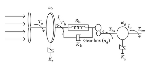
WT is a device which converts the kinetic energy of the wind in to electric energy. Simulation complexity of the WT purely depends on the type of control objectives. In case of WT modelling complex simulators are required to verify the dynamic response of multiple components and aerodynamic loading. Generally dynamic loads and interaction of large components are verified by the aeroelastic simulator. For designing a WT controller, instead of going with complex simulator, the design objective can be achieved by using simplified mathematical model. In this work WT model is described by the set of nonlinear ordinary differential equation with limited degree of freedom. This paper describes the control law for a simplified mathematical model with the objective of optimal power capture at below and above rated wind speed. The proposed controllers are validated for FAST WT model in three different cases of wind speed profile such as below rated wind speed (region 2), above rated wind speed (region 3) and a smooth transition between these two wind speeds (region 2.5). The parameter of the two-mass model is given in Appendix A. Generally VSWT system consists of the following components, that is, aerodynamics, drive trains, and generator, shown in Figure 1.

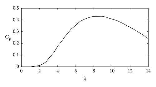
The values of approximated coefficients are given in Table 1. Figure 2 shows the Cp versus λ curve.
| a0 = 0.1667 | a3 = −0.01617 |
| a1 = −0.2558 | a4 = 0.00095 |
| a2 = 0.115 | a5 = −2.05 × 10⁻⁵ |
3. Problem Formulation
Figure 4 shows the various operating region in VSVPWT.
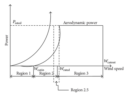
Region 1 represents the wind speed below the cut in wind speed. Region 2 represents the wind speed between cut in and rated wind speed. In this region the main objective is to maximize the energy capture from the wind with reduced oscillation on the drive train. Region 2.5 represents the wind speed nearer to the rated wind speed, that is, transient period. Region 3 describes the wind speed above the rated wind speed. In this region pitch controller is used to maintain the WT at its rated power.
3.1. Control Structure
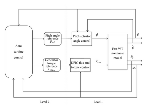
- (1)
The inner control loop consists of electrical generator with power converters.
- (2)
The outer loop has the aeroturbine control which gives the reference to the inner loop.
Figure 5 shows the WT control levels. In this paper we made an assumption that the inner loop is well controlled.
3.2. Control Objective
3.3. Classical Control Techniques
3.4. Wind Speed Estimation
4. Control Techniques for Below and Above Rated Wind Speed
4.1. Sliding Mode Control (SMC) for Optimal Power Extraction
The proposed control strategy combines MNR based estimator with second order sliding mode controller. SMC is one of the effective nonlinear robust approaches with respect to system dynamics and invariant to uncertainties. Lyapunov stability approach is used in SMC to keep the nonlinear system under control. The objective of the controller is to optimize the energy capture from the wind by tracking the reference rotor speed. In general designing SMC has two steps. First to find the sliding surface second is to develop the control signal U.
4.2. Integral Sliding Mode Control (ISMC) for Optimal Power Extraction
To improve the sliding surface and overcome the steady state error the integral action is included in the sliding surface.
4.3. Pitch Controller
5. Validation Results
The numerical simulations are performed on the CART (controls advanced research turbine) WT model and the characteristics are given in Table 2. The CART is located at the NREL (National Renewable Energy Laboratory) National Wind center near Golden, Colorado. The CART 3 is a three-blade variable speed, variable pitch WT with nominal power rating of 600 kW. It has mainly three parts, that is, rotor, tower, and nacelle. The rotor includes blade and their attachment points are called hub which is maintained by the low speed shaft. The tower is a cantilever beam which supports a yaw bearing and nacelle. The yaw bearing allows the turbine to rotate in the wind speed direction. The nacelle houses the complete drive train assembly. It contains the gearbox, generator, and low speed shaft. The gearbox is directly connected to the squirrel cage induction generator through high speed shaft. The generator is connected to the grid through power electronics that can directly control generator torque [25]. The power electronics consists of three-phase PWM (pulse width modulation) converters with a constant dc link voltage. The main objective of the grid side converter is maintaining the dc link voltage constant [26, 27].
| Rotor diameter | 43.3 m |
| Gear ratio | 43.165 |
| Tower height | 36.6 m |
| Nominal power | 600 kw |
| Maximum generator torque | 3.753 kNm |
5.1. Description for Simulator
FAST is an aeroelastic WT simulator which is developed by NREL. It can able to model both two- and three-blade horizontal axis wind turbine (HAWT). This FAST code can predict both extreme and fatigue loads. The tower and flexible blade are modeled by using the assumed mode method. Other components are modeled as rigid bodies. An advanced certified code is used in FAST to model the aerodynamic behavior of the WT. WT loads are calculated by using BEM (blade element momentum) and multiple component of wind speed profile [28]. FAST code is approved by the Germanischer Lloyd (GL) Windenergie GmbH for calculating onshore WT loads for design and certification [29]. Due to the above advantages and exact nonlinear modeling of the WT, the proposed controllers are validated by using FAST. In general three blade turbine has 24 DOF (degree of freedom) to represent the wind turbine dynamics. In this work 3 DOF is considered for WT, that is, variable generator, rotor speed, and blade teeter. FAST codes are interface with S-function and implemented with Simulink model. FAST uses an AeroDyn file as an input for aerodynamic part. AeroDyn file contains aerodynamic analysis routine and it requires status of a WT from the dynamic analysis routine and returns the aerodynamic loads for each blade element to the dynamic routine [30]. Wind profile acts as the input file for AeroDyn. The wind input file is generated by using TurbSim which is developed by the NREL.
In order to analysis the performance of the WT three cases are chosen.
5.2. Below Rated Wind Speed (Region 2)
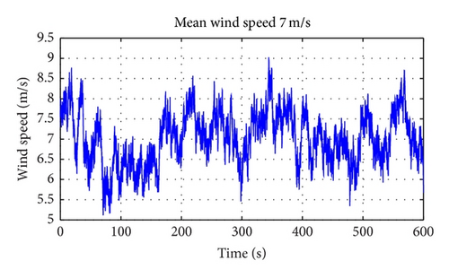
The test wind profile with full field turbulence is generated by using TurbSim developed by NREL. Figure 6 shows the hub height wind speed profile. In general any wind speed consists of two components, that is, mean wind speed and turbulence component. The test wind speed consists of 10 min dataset that was generated using Class A Kaimal turbulence spectra. It has the mean value of 7 m/s at the hub height, turbulence intensity of 25%, and normal IEC (International Electrotechnical Commission) turbulence type. The above wind speed is used as the excitation of WT.
- (1)
Maximization of the power capture is evaluated by the aerodynamic and electrical efficiency which is defined in (53).
- (2)
The reduced oscillation on the drive train and control torque smoothness are measured by the STD (Standard Deviation) and maximum value.
| Control strategy | ISC | ATF | SMC | ISMC |
|---|---|---|---|---|
| Std. (Tls) (kNm) | 9.629 | 23.03 | 21.84 | 13.59 |
| Max. (Tls) (kNm) | 45.62 | 130.8 | 131.4 | 73.4 |
| Std. (Tem) (kNm) | 0.142 | 0.369 | 0.252 | 0.198 |
| Max. (Tem) (kNm) | 1.010 | 2.500 | 1.690 | 1.260 |
| ηelec (%) | 69.73 | 72.87 | 76.89 | 76.26 |
| ηaero (%) | 85.59 | 85.06 | 96.78 | 96.56 |
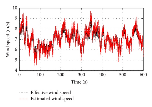
Figure 7 shows the estimation of effective wind speed by using the Modified Newton Raphson (MNR) estimator. The MNR estimator gives the correct reference which ensures the dynamic aspect of wind.
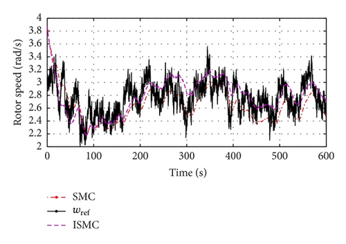
The rotor speed comparisons for FAST simulator are shown in Figures 8 and 9. The conventional controllers such as ATF and ISC are not able to track the optimal reference speed. ATF has only single tuning parameter, that is, Kc, which cannot minimize the steady state error. In ISC, during fast transient wind speed, it introduces more power loss. More over these controllers are not robust with respect to high turbulence wind speed profile. To overcome the above drawbacks SMC and ISMC are proposed. Figure 9 shows the rotor speed comparisons for ISMC and SMC. It is found that ISMC and SMC track the reference rotor speed better than ISC and ATF.
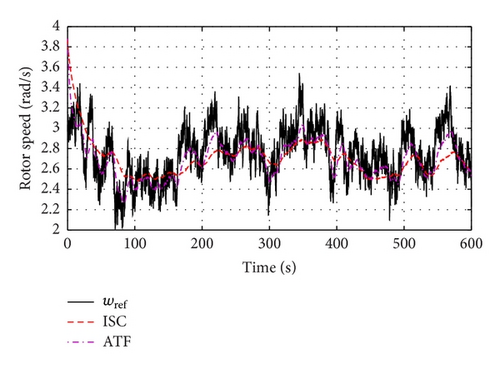
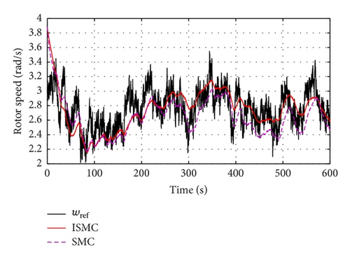
Table 3 gives the performance analysis of all the conventional and proposed controllers. From Table 3, it is clear that the STD of Tem and Tls is less for ISMC compared to SMC and ATF. This ensures the smoothness of the control input and low speed shaft torque in ISMC compared SMC and ATF. Table data shows that ISC having lowest STD of Tem and Tls, but its efficiency is very low (69.73%) compared to all other controllers. So a trade-off should be made between the efficiency and the fatigue load on drive train.
To analyze the controller performances in a more detailed fashion, Figures 10 and 11 show the box plot for low speed shaft torque and generator torque with the mean, median, ±25% quartiles (notch boundaries), ±75% quartiles (box ends), ±95% bounds, and the outliers. From the size of the boxes shown, it is clear that the ISC experiences minimum variation than others. It ensures that ISC having the minimum transient load on the drive train; at the same time, we have seen from Table 3 that the efficiency of ISC is not comparable with other controllers. Comparing the box plot of ISMC and SMC, ISMC has less variation in low speed shaft torque and generator torque; this indicates smoothness of the controller and reduction in transient load.
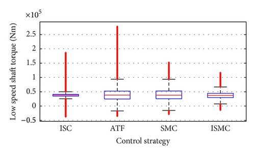
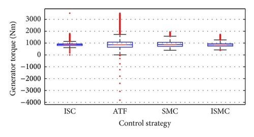
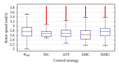
Figure 12 shows the boxplot for rotor speed for FAST simulator. From this figure it is observed that ISMC and SMC have almost same variation in the reference rotor speed. Apart from ISMC and SMC, other controllers such as ATF and ISC are having more variations in reference speed.
The frequency analysis is carried out by using the PSD on the low speed shaft torque which is shown in Figure 13. As the SMC plot is completely above the ISMC plot, it can be concluded that low speed shaft torque variation is more for SMC than ISMC. This indicates that ISMC gives minimum excitation to the drive train compared to SMC.
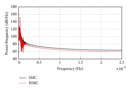
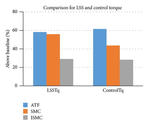
Figure 14 shows comparison of low speed shaft torque and control torque for ATF, SMC, and ISMC by considering ISC as baseline control. All the low speed shaft torques (LSSTq) and control torques (ControlTq) are having higher values compared to baseline controller.
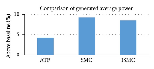
As shown in Figure 15 the SMC controller has improved power capture by 0.75% compared to ISMC. An intermediate tracking has been chosen and a compromise has been made between efficiency and load mitigation. From the above analysis and results given in Table 3 it is observed that even though SMC gives slightly more efficiency than ISMC, by considering transient load on drive train and smooth control input, ISMC found be optimal.
In order to avoid the torsional resonance mode by choosing the proper tracking dynamics a trade-off is made between power capture optimization with smooth control and reduced transient load on low speed shaft torque. A good dynamic tracking; that is, similar to WT fast dynamics gives better power capture but it requires more turbulence in control torque. Conversely slow tracking gives smooth control action with less power capture. The simulations are performed with different mean wind speed at region 2. The results are given in Tables 4 and 5. From these tables it observed that with an increase in mean wind speed the maximum value of the control input (Tem) also increases. In all the cases both SMC and ISMC controllers are having almost same efficiency but the transient load reduction is better for ISMC. As the mean wind speed increases the rate of increase of STD is more for SMC than ISMC. It observed that when the wind speed undergoes high variation the ISMC can produce better power capture with reduced transient load on the drive train.
Mean wind speed (m/sec) |
Electrical efficiency (%) |
Tls standard deviation kNm |
Max (Tem) kNm |
|---|---|---|---|
| 7 (m/sec) | 76.89 | 21.84 | 1.690 |
| 8 (m/sec) | 74.51 | 20.31 | 1.783 |
| 8.5 (m/sec) | 74.22 | 20.11 | 1.922 |
Mean wind speed (m/sec) |
Electrical efficiency (%) |
Tls standard deviation kNm |
Max (Tem) kNm |
|---|---|---|---|
| 7 (m/sec) | 76.26 | 13.59 | 1.260 |
| 8 (m/sec) | 74.49 | 11.72 | 1.526 |
| 8.5 (m/sec) | 74.68 | 11.98 | 1.762 |
5.3. Transition between Below and Above Rated Wind Speed (Region 2.5)
Figure 16(a) shows the test wind speed consists of 10 min dataset that was generated by the binary file format. In this wind profile the wind speed changes in step of every 50 sec starts from 6 m/sec to 18 m/sec. This shows both the above and below rated wind speed are included in the wind profile. For below rated wind speed torque control comes into action with constant pitch angle and above rated wind speed pitch control comes into action with rated torque. Figure 16(b) shows the generator speed for SMC and ISMC for below and above rated wind speed. Both controllers achieve the nominal value of the generator speed at 250 sec. The corresponding wind speed is around 11.5 m/sec which can be seen from Figure 16(a). As the wind speed approaches towards the rated speed the WT generator speed reaches the nominal value, that is, 167.55 rad/sec. Figure 16(c) shows the electrical power comparison for SMC and ISMC for the transition period. At region 2.5 ISMC can able to extract the more power than SMC with almost same mechanical stress on the drive train. Figure 16(d) shows the generator torque comparison in region 2.5 for SMC and ISMC. It can be observed that ISMC produces more generated torque compared to SMC in region 2.5, that is, 250 sec to 400 sec. As generator speed remains constant from 200 sec onwards it is obvious that ISMC captures more power compared to SMC. The STD of generated torque for SMC and ISMC is found to be 1.060 kNm and 1.07 kNm respectively which is almost same. Figure 16(e) shows the pitch angle comparison for SMC and ISMC at region 2.5. Pitch variation found to be more for SMC compared to ISMC. So the pitch actuator needs more control action for SMC + PI.
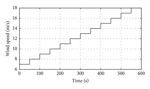
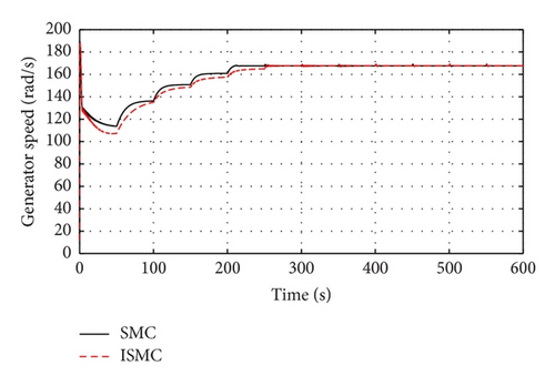
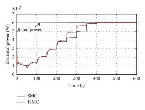
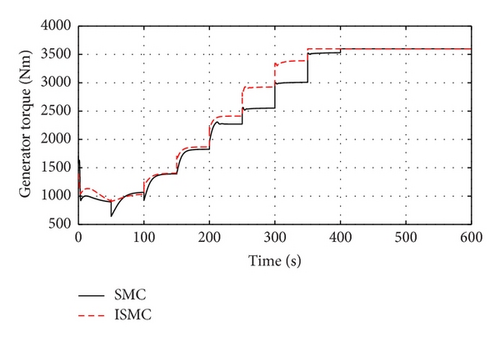
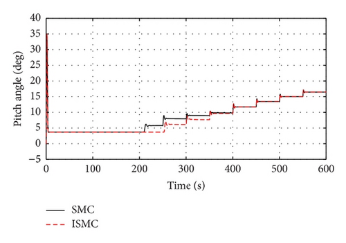
Figure 17(a) shows the test wind speed consists of 10 min dataset that was generated by the binary file format. In this wind profile the wind speed changes with vertical wind profile starts from 6 m/sec to 18 m/sec. This shows both the above and below rated wind speed are included in the wind profile. Figure 17(b) shows the generator speed for SMC and ISMC for below and above rated wind speed. Both controllers achieve the nominal value of the generator speed at 280 sec. The corresponding wind speed is around 11.5 m/sec which can be seen from Figure 17(a). As the wind speed approaches towards the rated speed the WT generator speed reaches the nominal value, that is, 167.55 rad/sec. Figure 17(c) shows the electrical power comparison for SMC and ISMC for the transition period. At region 2.5 ISMC can extract more power than SMC with almost the same mechanical stress on the drive train. Figure 17(d) shows the generator torque comparison in region 2.5 for SMC and ISMC. It can be observed that ISMC produces more generated torque compared to SMC in region 2.5, that is, 280 sec to 415 sec. As generator speed remains constant from 280 sec onwards it is obvious that ISMC captures more power compared to SMC. Figure 16(e) shows the pitch angle comparison for SMC and ISMC at region 2.5. Pitch variation was found to be more for SMC compared to ISMC. So the pitch actuator needs more control action for SMC + PI.
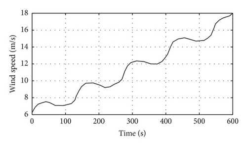
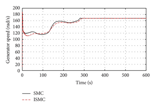
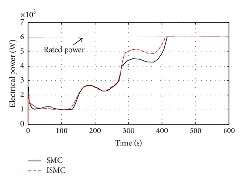
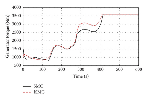
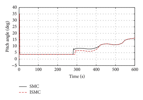
Figure 18 shows the rotor speed comparison of SMC and ISMC controller with the rotor inertia parameter uncertainty (+30%) and disturbance of 5/ng kNm. From this figure it is concluded that with the disturbance and uncertainty ISMC can track the reference rotor speed which ensures the robustness with respect to uncertainty and disturbance.
6. Conclusion
In this paper a combination of linear and nonlinear control for VSVPWT has been proposed. The proposed nonlinear controller such as SMC and ISMC is designed for wide range of below rated wind speed profiles. The main aim of the controller is to capture the maximum power with reduced oscillation on the drive train at below rated speed. The simulation of the controllers is performed by NREL CART 3, 600 kW WT. From the analysis it is concluded that the proposed ISMC (region 2) with conventional PI controller (region 3) can achieve the maximum power in all the regions of wind speed.
Conflict of Interests
The authors declare that there is no conflict of interests regarding the publication of this paper.
Appendices
A. Two-Mass Model Parameters
-
Rotor radius: R = 21.65 m,
-
air density: ρ = 1.29 kg/m3,
-
rotor inertia: Jr = 3.25 · 105 kg·m2,
-
generator inertia: Jg = 34.4 kg·m2,
-
shaft damping coefficient: Kls = 9500 Nm/rad,
-
shaft stiffness coefficient: Bls = 2.691 · 105 Nm/rad,
-
rotor friction coefficient: Kr = 27.36 Nm/rad/sec,
-
generator friction coefficient: Kg = 0.2 Nm/rad/sec,
-
gear ratio: ng = 43.165,
-
cut in wind speed: 6 m/sec,
-
rated wind speed: 13 m/sec,
-
cut out wind speed: 25 m/sec.
B. Modified Newton Raphson Algorithm
-
Step 1: ,
-
Step 2: ,
-
Step 3: n = n + 1,
-
Step 4: Stop if n > nmax or |υn − υ(n − 1)|/υn < εmin go to Step 2,
-
Step 5: nf = n,


