Volume 2014, Issue 1 650835
Research Article
Open Access

Output Feedback Adaptive Stabilization of Uncertain Nonholonomic Systems

Yuanyuan Wu

Yuanyuan Wu

College of Electric and Information Engineering, Zhengzhou University of Light Industry, Zhengzhou, Henan 450002, China zzuli.edu.cn

Department of Mathematics, Southeast University, Nanjing, Jiangsu 210096, China seu.edu.cn

Search for more papers by this author
Zicheng Wang

Zicheng Wang

College of Electric and Information Engineering, Zhengzhou University of Light Industry, Zhengzhou, Henan 450002, China zzuli.edu.cn

Search for more papers by this author
Yuqiang Wu

Yuqiang Wu

Research Institute of Automation, Qufu Normal University, Qufu, Shandong 273165, China qfnu.edu.cn

Search for more papers by this author
Qingbo Li

Corresponding Author

Qingbo Li

College of Mathematics and Information Science, Zhengzhou University of Light Industry, Zhengzhou, Henan 450002, China zzuli.edu.cn

Search for more papers by this author
First published: 12 May 2014
Academic Editor: Hao Shen

Abstract

This paper investigates the problem of output feedback adaptive stabilization control design for a class of nonholonomic chained systems with uncertainties, involving virtual control coefficients, unknown nonlinear parameters, and unknown time delays. The objective is to design a robust nonlinear output-feedback switching controller, which can guarantee the stabilization of the closed loop systems. An observer and an estimator are employed for states and parameters estimates, respectively. A constructive controller design procedure is proposed by applying input-state scaling transformation, parameter separation technique, and backstepping recursive approach. Simulation results are provided to show the effectiveness of the proposed method.

1. Introduction

The control and feedback stabilization problems of nonholonomic systems have been widely studied by many researchers. It is well known that control of nonholonomic systems is extremely challenging, largely due to the impossibility of asymptotically stabilizing nonholonomic systems via smooth time-invariant state feedback, a well-recognized fact pointed out in [1, 2]. In order to overcome this obstruction, a number of approaches have been proposed for the problem, which mainly include discontinuous feedback, time-varying feedback, and hybrid stabilization. The discontinuous feedback stabilization was first proposed by [3], and then further discussion was made in [47]; especially an elegant discontinuous coordinate transformation approach is proposed in [5] for the stabilization problem of nonholonomic systems. Meanwhile, the smooth time-varying feedback control strategies also have drawn much attention [811].

As pointed out in [9], many nonlinear mechanical systems with nonholonomic constraints can be transformed, either locally or globally, to the nonholonomic systems in the so-called chained form. So far, there have been a number of controller design approaches [825] for such chained nonholonomic systems. Recently, adaptive control strategies have been proposed to stabilize the nonholonomic systems. For instance, the problem of adaptive state-feedback control is studied in [1519], while output feedback controller design in [2024]. Considering the actual modeling perspective, time delay should be taken into account. The problem of state feedback stabilization is studied for the delayed nonholonomic systems in [25, 26]. However, the virtual control coefficients and unknown parameter vector are not considered in its system models. Here, an iterative controller design method will be proposed for the output feedback adaptive stabilization of the concerned delayed nonholomic systems.

In this paper, we study a class of chained nonholonomic systems with strong nonlinear drifts, and the problem of adaptive output-feedback stabilization for the concerned nonholonomic systems is investigated. The constructive design method proposed in this note is based on a combined application of the input scaling technique, the backstepping recursive approach, and the novel Lyapunov-Krasovskii functionals. The switching control strategy for the first subsystem is employed to achieve the asymptotic stabilization.

The rest of this paper is organized as follows. In Section 2, the problem formulation and some preliminary knowledge are given. Section 3 presents the controller design procedure and stability analysis. Section 4 gives the switching control strategy. In Section 5, numerical simulations testify to the effectiveness of the proposed method, and Section 6 summarizes the paper.

2. Problem Formulation and Preliminaries

In this paper, we deal with a class of nonholonomic systems described by
(1)
where [x0(t), x(t)] T = [x0(t), x1(t), …, xn(t)] TRn+1,  u(t) = [u0(t), u1(t)] TR2, and y(t) ∈ R2 are system states, control input, and measurable output, respectively; θRm is an unknown parameter vector; ϕ0 (known) and ϕi  (1 ≤ in) (unknown) denote the possible modeling error and neglected dynamics; φi  (1 ≤ in) are known modeled dynamics, which contain output delays; τi  (1 ≤ in) are unknown constants, and di  (0 ≤ in) referred to the respective virtual control coefficients.

In this paper, we make the following assumptions on the virtual control directions di and nonlinear functions φi, ϕi in system (1).

Assumption 1. d0 is a known constant and the sign of is known, where .

Assumption 2. There exist known smooth nonnegative functions and such that

(2)
for all (t, u0(t), x0(t), x(t), θ) ∈ R+ × R × R × Rn × Rm.

Assumption 3. For every 1 ≤ in, the nonlinear function φi satisfies inequality

(3)
in which and ψi are known smooth nonnegative nonlinear functions.

Remark 4. Compared with some existing literatures in recent years, the structure of our concerned system (1) is more general. For instance, in [15], it is assumed that not only the virtual control directions di = 1 and the dynamics ϕi satisfy , but also the modeled dynamics φi do not exist. In [22], the virtual control coefficients and time delays have not been considered, and the expression is also required. While di = 1 and φi and unknown parameters θ are not existent, system (1) degenerates to the one studied in [21]. When φi = 0, together with , system (1) becomes the considered system in [23].

Remark 5. Note that here we only use the sign of without any knowledge of individual virtual control direction di  (1 ≤ in). Moreover, Assumptions 2 and 3 are imposed on the nonlinear functions ϕi and φi, respectively. In fact, if the modeled dynamics φi do not involve time delays, inequality (3) is reduced into

(4)
It can be seen that the above inequality condition is used in some existing literatures, such as [20, 21], and so on.

Our object of this paper is to design adaptive output feedback control laws under Assumptions 13, such that the system states (x0(t), x(t)) converge to zero, while other signals of the closed-loop system are bounded. The designed control laws can be expressed in the following form:
(5)
Next, we list some lemmas which will be applied in the coming controller design.

Lemma 6 (see [27].)For any real-valued continuous function f(x, y), where xRn, yRm, there are smooth functions a(x) ≥ 0, b(y) ≥ 0, c(x) ≥ 1, d(y) ≥ 1 such that

(6)

Lemma 7 (see [19].)For any continuous function μ0(t) there exist two strictly positive real numerates pmin⁡ and pmax⁡ such that the unique solution P(t) of the following matrix differential equation:

(7)
satisfies   pmin⁡IP(t) ≤ pmax⁡I,   t ≥ 0.

By Lemma 6 and Assumption 1, we know that there exist smooth functions ωi ≥ 1, and ζi ≥ 1 such that
(8)
Furthermore, we denote ; then it yields
(9)

3. Output Feedback Adaptive Stabilization Control Design

In this paper, we design control laws u0(t) and u1(t) separately to globally asymptotically stabilize the system (1). According to the structure of system (1), we can see that when x0(t) converges to zero, xi(t)  (1 ≤ in) will be uncontrollable. A widely used method to design control law u1(t) is to introduce a discontinuous input scaling transformation (12). On the other hand, the control directions di are unknown; then we should employ another coordinate transformation to overcome the obstacle.

3.1. State Coordinate Transformation

Firstly, we design the coordinate transformation as follows:
(10)
where and . Then, the system (1) can be transformed into
(11)
Next, the following input-state scaling discontinuous transformation is introduced:
(12)
Under the new z(t)-coordinates, the -subsystem (10) is changed into
(13)
Next, we can design the control laws u0(t) and u1(t) to asymptotically stabilize the states x0(t) and z(t), respectively. Rewrite system (13) in the compact form
(14)
where
(15)
with
(16)

In order to obtain the estimation for the nonlinear functions Ψi and Φi, the following lemmas are given.

Lemma 8. For every 1 ≤ in, there exists smooth nonnegative function such that

(17)

Lemma 9. For every 1 ≤ in, there exist smooth nonnegative functions such that

(18)

Remark 10. By lemmas and assumptions before, Lemmas 8 and 9 can be derived easily, and then the proof is omitted.

3.2. Observer Design

Define the following filter/estimator:
(19)
(20)
(21)
where y(t) = z1(t), en = [0, …, 1] T, ξ0 = [ξ01, …, ξ0n] T, υ = [υ1, …, υn] T, A0 = AKC, C = [1,0, …, 0], K = [k1, …, kn] T, and ki  (1 ≤ in) are design parameters to be determined later. Let ; then, the estimation error and the newly defined parameter σ(t) satisfy the dynamical equations
(22)

3.3. Control Design

In this section, the intergrator backstepping approach will be used to design the control laws u0(t) and u1(t) subject to x0(t0) ≠ 0. The case that the initial condition x0(t0) = 0 will be treated in Section 4.

Step  0. At this step, control law u0(t) will be designed, which is essential to guarantee the effectiveness of the subsequent steps. For the x0(t)-subsystem, choose the control u0(t) as follows:
(23)
where λ0 is a constant satisfying λ0d0 > 1. Introduce the Lyapunov function candidate , and the time derivative of V0 satisfies
(24)
where c0 = λ0d0 > 1. This indicates that x0(t) converges to zero exponentially.
Since is a smooth function, then there exist a constant M0 > 1, such that for |x0(t)| ≤ 1. Therefore, the following inequality is true with |x0(t)| ≤ 1:
(25)
which implies that when |x0(t)| ≤ 1, the state x0(t) converges to zero with a rate less than a certain constant ρ. It is x0(t) which does not become zero in any time instant. Therefore, the adopted input-state scaling discontinuous transformation in (12) is effective.
According to the design of control law u0(t) in (23), it can be computed that
(26)
where β = −λ0d0 and + .

Remark 11. From (26), we know that β is a constant and is a function with respect to x0(t). Moreover, we can conclude that is smooth because is a nonnegative smooth function.

Denote A1 = A0KCLβ; we can choose appropriate design parameters ki  (1 ≤ in) such that A1 is Hurwitz. Then there exists a positive definite matrix Q satisfying , and μ is a positive constant.

Step  1. For z1(t)-subsystem in (13),
(27)
let η1(t) = z1(t), and η2(t) = υ2(t) − α1. Introduce the following Lyapunov functional:
(28)
where
(29)
with 1, δ2 being positive constants to be designed; , where Θ1 is an unknown parameter vector to be specified later, and is an estimate of Θ1.
Associated with (22) and (27), the time derivatives of and can be calculated, respectively, that
(30)
(31)
For some terms on the right-hand side of (30), the following estimations (32)–(34) should be conducted. Firstly, by Lemma 8 and Young’s inequality, we can obtain that there exist positive constants 1, δ1 to make the following inequalities hold:
(32)
where . Next, employ Lemma 9 and Young’s inequality, and we have
(33)
where , and δ2 is a positive constant.
By completing the square, the following estimations are also true:
(34)
Substitute (31)–(34) into , it yields
(35)
where , and Υ1 = [Υ11, Υ12, Υ13] T with
(36)
Choose the virtual control function α1 and the adaptation law of as follows:
(37)
(38)
Notice that , then it follows from (35)–(38) that
(39)
Step  2. Introduce the new variable η3(t) = υ3(t) − α2, where α2 is regarded as the virtual control input, and take the Lyapunov functional as
(40)
where , Θ2 is an unknown parameter vector to be defined later, and is an estimate of Θ2. Then, combined with (20), (37), and (39), we have
(41)
Using Lemmas 8 and 9 and Young’s inequality, the following inequalities hold:
(42)
By the above inequalities, we get
(43)
where and . By taking the adaptation law and the virtual control function α2 as
(44)
we can obtain
(45)
Step  3. Define that η4(t) = υ4(t) − α3, where α3 is the virtual control input, and consider the following Lyapunov functional:
(46)
The time derivative of V3 along the estimator system (20) satisfies
(47)
By similar conduction method in (42), we have
(48)
where 3 > 0 is a scalar. Based on (48), it yields
(49)
where and . Choose the tuning function π3Υ3η3(t), and the virtual control function α3 as follows:
(50)
Under the virtual control function α3 and the tuning function π3 defined above, the derivative of V3 becomes that
(51)

Step i (4 ≤ i ≤ n). Assume that, at Step i−1, a virtual control function αi−1, a tuning function πi−1, and a Lyapunov functional Vi−1 have been designed in such a way that

(52)

Let ηi+1(t) = υi+1(t) − αi, where αi is regarded as the virtual control input, and choose Lyapunov functional as
(53)
Based on (52), the time derivative of Vi satisfies
(54)
Next, we estimate the following terms in the right-hand side of (53) by Lemmas 8 and 9 and Young’s inequality as follows:
(55)
Choosing the virtual control function αi as
(56)
and the tuning function πi = πi−1 + Υiηi(t) with . Then, we can show that
(57)

At the last step (i = n), the true input u1(t) will be designed on the basis of the virtual control and the Lyapunov function Vn−1 introduced before.

The actual control input u1(t) can be designed as
(58)
and the update law with πn = πn−1 + Υnηn(t) and . Eventually, it can be achieved that
(59)

3.4. Stability Analysis

Notice that tends to zero as x0(t) converges to origin, and δ1, δ2, i, ci  (1 ≤ in) in (59) are positive design parameters. Therefore, by an appropriate parameter choice, there exist positive constants λi > 0  (1 ≤ in + 2) such that
(60)

It can be seen that are bounded. Since θ and di are unknown bounded parameters, are bounded. According to estimator equations (19)–(21), it can be deduced that the boundedness of z1(t) = η1(t) guarantees the boundedness of ξ0(t), and then and α1 are also bounded. By similar analysis, we can conclude that all signals of the closed loop system are bounded.

By LaSalle invariant Theorem, it further achieves that as t. By the controller design procedure, we get that ξ0(t), υ(t), αi, u1(t) asymptotically tend to zero. Then, the definitions and show the asymptotical convergence of and z(t). Finally, from the transformations (10) and (12), we know , which indicates that the states xi(t) asymptotically converge to zero with the initial condition x0(t0) ≠ 0.

For purposes of analysis, we can rewrite the system (14) as follows:
(61)
To solve the above differential equation, we have
(62)
Notice that A1 = AKCLβ is Hurwitz, and tends to zero as x0(t) → 0, then by Lemmas 8 and 9, there exist constants ϱ1 > 0, ϱ2 > 0 such that
(63)
where is a nonnegative smooth function of di, u0(s), u0(sτi), y(s), y(sτi), and is a nonnegative smooth function of di, u0(s), x0(s), z1(s), ϑ.

Since x0(t), x1(t), u0(t) and the system parameters are all bounded, then in (63) are also bounded. Employing the convergence of x0(t), z1(t), u1(t), we can get that z(t)-system is globally asymptotically convergent. From the introduced transformations before, it can be deduced that system (1) is also asymptotically convergent. Now, we can express the following theorem.

Theorem 12. For system (1), under Assumptions 13, if the control strategies (23) and (58) are applied with an appropriate choice of the design parameters, the global asymptotic stabilization of the closed loop system is achieved for x0(t0) ≠ 0.

In the next section, we will deal with the stability analysis of the closed loop as long as the initial condition x0(t0) is zero.

4. Switching Controller

Several switching controllers have been proposed in some existing literatures. As well known, the choice of a constant feedback for u0(t) may lead to a finite escape. In this note, the following switching category can be designed for the stabilization of system (1) with the initial sate x0(t0) = 0. Choosing controller u0(t) as
(64)
where and ϱ3 > 0 are constants.
Since x0(t0) = 0, then with u0(t) can be deduced
(65)
then during the initial small time period, x0(t) is increasing and satisfies .
Choose that satisfy
(66)

Obviously, x0(t) is increasing when . When , choose the controller , and the controller u1(t) can be designed according to the simple nonlinear backstepping iterative approach. Since |x0(t)| > ϱ3, at ts, we switch the control laws u0(t) and u1(t) into (23) and (58), respectively.

Theorem 13. For system (1), under Assumptions 13, if above switching control strategy is applied with an appropriate choice of the design parameters, then the closed-loop system is globally asymptotic regulated at the origin for x0(t0) = 0.

5. Simulation Example

In this section, a numerical example will be given to illustrate that the proposed systematic control law design method is effective. Consider the following system:
(67)
where d0, d1, d2 are virtual control directions with d1, d2 unknown and d0 known, and the sign of is also known. θ1, θ2 are unknown bounded parameters. Next, we consider to design the controller u0(t) and u1(t) to asymptotically stabilize system (67) by the measurable output. We assume that x0(t0) ≠ 0 and make the following estimation for some nonlinear terms in system (67):
(68)
where .
Firstly, we introduce the following transformation:
(69)
and then the system (67) can be rewritten as
(70)
where , and assume that the sign of is known.
Next, make the following input scaling transformation for -system:
(71)
and then the transformed system is
(72)
where
(73)
Design the following controller u0(t):
(74)
and then can be calculated as follows:
(75)
For system (72), constructing the following estimator:
(76)
where y(t) = z1(t), en = [0,1] T, ξ0 = [ξ01, ξ02] T, υ = [υ1, υ2] T, A0 = AKC,   C = [1,0], and K = [k1, k2] T. The design of k1,   k2 can guarantee that A1 = A0KCLβ is Hurwitz. It is further achieved that there exists plosive definite matrix Q satisfying , in which μ > 0 is a constant. Denote and , and then the observation error ɛ(t) and parameter invariable σ(t) satisfy
(77)
Define the invariable that η1(t) = z1(t), η2(t) = υ2(t) − α1. According to the iterative procedure in Section 3, we can design the virtual control function and controller u1(t) as
(78)
where
(79)
The adaption laws of the parameter invariable in controller u1(t) are chosen as
(80)

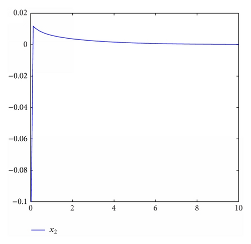
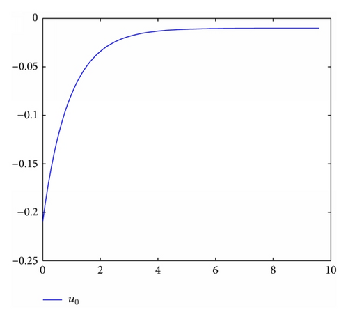
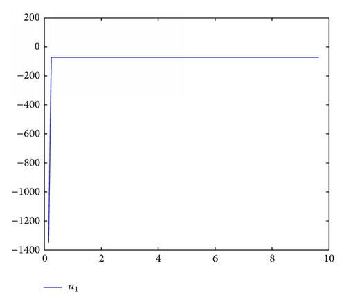
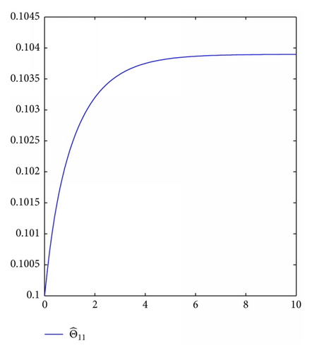
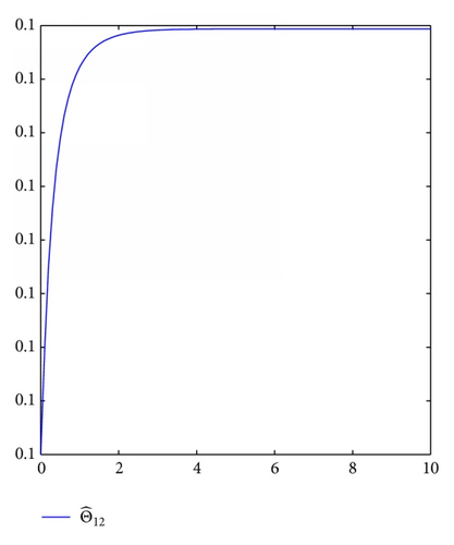
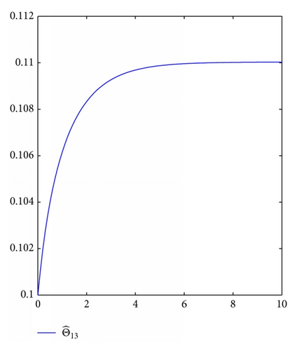
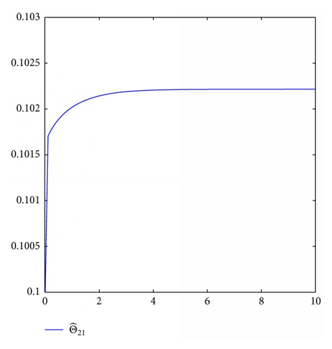
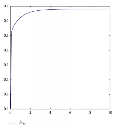
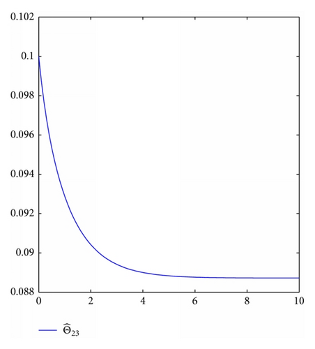
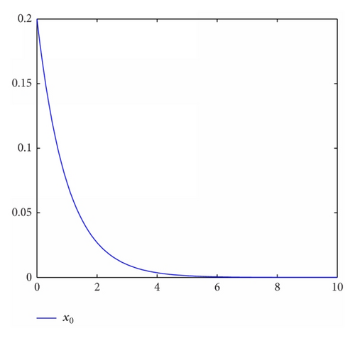
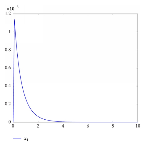
For simulation use, we pick the unknown parameters d1 = 1.5,  d2 = 2.5,  θ1 = θ2 = 0.5. In addition, we take the other controller design parameters as c0 = 1, c1 = 130, c2 = 2,  k1 = 4,  k2 = 1,  1 = 2,   2 = 3,  δ1 = δ2 = 4. Moreover, The initial state condition is [0.2, 0,    − 0.1] T. Simulation results are shown in Figures 1, 2, 3, and 4. It is obvious that the states x0(t), x1(t), x2(t) and control input u0(t), u1(t) converge to zero, and the parameters estimation invariable tend to constants.
Details are in the caption following the image
States x0(t), x1(t), x2(t).
Details are in the caption following the image
States x0(t), x1(t), x2(t).
Details are in the caption following the image
States x0(t), x1(t), x2(t).
Details are in the caption following the image
Controllers u0(t) and u1(t).
Details are in the caption following the image
Controllers u0(t) and u1(t).
Details are in the caption following the image
Parameters .
Details are in the caption following the image
Parameters .
Details are in the caption following the image
Parameters .
Details are in the caption following the image
Parameters .
Details are in the caption following the image
Parameters .
Details are in the caption following the image
Parameters .

6. Conclusion

The output-feedback adaptive stabilization was investigated for a class of nonholonomic systems with unknown virtual control coefficients, nonlinear uncertainties, and unknown time delays. In order to overcome the difficulties, we introduce suitable transformation and novel Lyapunov-Krasovskii functionals, and then a recursive technique is given to design the adaptive controller. To make the input-state scaling transformation effective, the switching control strategy is employed to achieve the asymptotic stabilization.

Conflict of Interests

The authors declare that there is no conflict of interests regarding the publishing of this paper.

Acknowledgments

This work is partially supported by National Natural Science Foundation (U1304620,61273091,61374079), Basic and Frontier Technologies Research Program of Henan Province (122300410279), and Doctoral Fund of Zhengzhou University of Light Industry (201BSJJ006).

      The full text of this article hosted at iucr.org is unavailable due to technical difficulties.