Multimodel Robust Control for Hydraulic Turbine
Abstract
The paper deals with the multimodel and robust control system design and their combination based on M − Δ structure. Controller design will be done in the frequency domain with nominal performance specified by phase margin. Hydraulic turbine model is analyzed as system with unstructured uncertainty, and robust stability condition is included in controller design. Multimodel and robust control approaches are presented in detail on hydraulic turbine model. Control design approaches are compared and used for derivation of new approaches which combine advantages of both.
1. Introduction
When hydraulic turbine power control is considered, the water inertia effect is a factor that makes it difficult to maintain stability under isolated operation or to have fast response in case of load change in the whole operational range. Nonlinear models of hydraulic turbine control systems are needed in those cases where the turbine power varies in the whole range. The turbine model parameters vary significantly with the unpredictable load variations. Such nonlinearities make the controller design a nontrivial task due to the fact that a controller designed for specific operating conditions may not perform well under different loads [1]. This fact leads to the adaptive [2] or hybrid control algorithms.
There are several approaches to model hybrid systems [3]. In a model of a large class of hybrid systems, [4] is considered as discrete event system and continuous dynamic modeled by differential or difference equation. Such models are used to formulate a general stability analysis and controller synthesis framework for hybrid systems. Results for modeling and stability analysis of hybrid systems have been presented in [3, 5, 6]. In this paper, we follow the class of hybrid system known as switched systems [7].
In this paper, hybrid control, often denoted by multimodel control, will be used. Several switching algorithms will be compared to show how the switching speed affects performance and stability. Well-known robust control method will be presented as a control solution which ensures stability on whole operating range, but with lower performance. Combination of multimodel control and robust control which ensure stability and good performance will be presented on numerical example of nonlinear hydraulic turbine model.
2. Preliminaries and Problem Formulation
To deal with uncertainties instead of a single model, the behavior of a class of models Π is considered.
Multimodel control is based on several linear models identified in operating points. For each linear model, local controller is designed which ensures stability and perhaps even performance only for this model. As nonlinear system moves from one operating point to another, controller switches from one local controller to another one. Performance of this control approach can be much better as using only one controller on whole range, but this method does not yield stability when nonlinear system is between operating points. Fast switching between local controllers can decrease performance and also lead to instability.
In robust control, several linear models identified in operating points are used for uncertainty model calculation. Then, for system control, one controller is used, which ensures stability on whole operating range, between all operating points. Performance (of robust control) is not so good as performance of multimodel control; however, there is no problem with stability by controllers switching. When nonlinearity is increased, uncertainty is increased too and performance of robust control decreases. If the system is strongly nonlinear, uncertainty could be too big to be able to control the system using robust control.
In this paper, designing a set of local controllers similar to those in multimodel control design will be done, but each local controller will be designed as robust to ensure stability between operating points. By robust design of local controller, instead of all operating points, only given and neighbourhood operating points will be considered. This type of control will be called robust multimodel control and will ensure stability and higher performance than robust control.
3. Theoretical Results
3.1. Multimodel Control Design
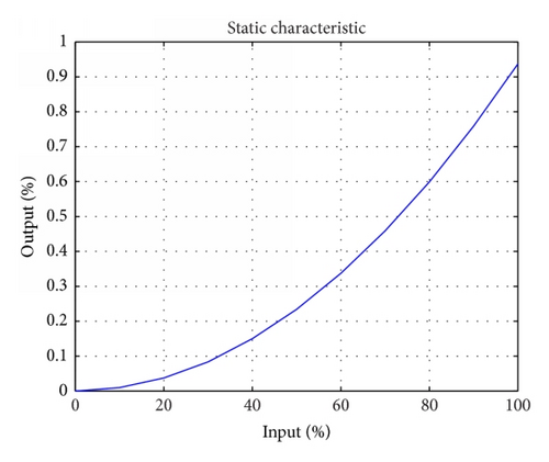
Consider a system with nonlinear static characteristic (Figure 2).
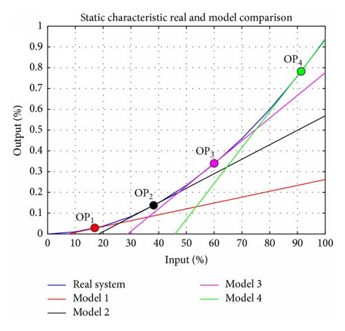
Static characteristic is nonlinear and could be approximate using m linear models (in our case four models, m = 4, Figure 3).
These models are simple to obtain using input-output identification. For each model (operating point (OP)), local PID controller can be tuned using any well-known and tested method. Depending on system output, multimodel controller switches between local PID controllers. Local controllers ensure stability only in operating point.

3.2. Robust Control Design
- (1)
Additive uncertainty model for operating points q = 1,2, …, m:
()
- (2)
Input multiplicative uncertainty model for operating points q = 1,2, …, m:
()
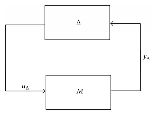
Standard feedback configuration with unstructured uncertainty of any type can be rearranged to obtain the general M − Δ structure in Figure 4 where M(s) represents the transfer function matrix (containing controller R(s) nominal model G0(s)) and Δ(s); σmax[Δ(jω)] ≤ 1 is the normalized perturbation.
- (i)
for additive uncertainty:
() - (ii)
for input multiplicative uncertainty:
()
- (a)
Nominal model calculation: nominal model G0(s) is calculated as average transfer function from all m operating points Gq(s), q = 1,2, …, m.
- (b)
For nominal model standard feedback controller is designed: good choice could be controller design method with desired phase margin.
- (c)
Robust stability verification according to (13): if robust stability is not passed, part (b) must be done again. Increasing phase margin by controller design is possible to improve robust properties of controller.
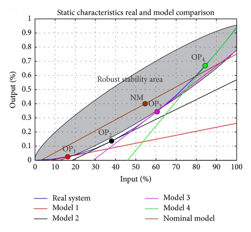
Note: segments (4) are inclusive of robust stability area.
3.3. Robust Multimodel Control Design
In this case, for each operating point of switched system, with arbitrary switch algorithm, robust controller Rq(s), q = 1,2, …, m is designed. Controller guarantees the robust stability and performance for all operating points and over the entire operating range specified by uncertain models (5) or (7).
Robust controller design procedure for each operating point q = 1,2, …, m of switched system goes the same way as for robust control design but instead of all operating points only given and neighbourhood operating points are considered.
- (a)
For each operation point, nominal model is calculated using not all but only neighborhood operating points. Nominal model G0n(s) is for qth operating point calculated as average one from Gq(s), Gq−1(s), Gq+1(s) (if q = 1 only Gq(s) and Gq+1(s) are considered. If q = m only Gq(s) and Gq−1(s) are considered).
- (b)
For nominal model G0n(s) standard feedback controller is designed. Good choice could be controller design method with desired phase margin.
- (c)
Robust stability verification according to (13): if robust stability is not passed, part (b) must be done again. Increasing phase margin by controller design is possible to improve robust properties of controller.
These three steps have to be done m times once for each operating point.
Stability areas of local controllers (Figure 6) are overlapping so nonlinear system is stable also between operating points. Robust stability area is smaller like using only one robust controller which will yield less conservative solutions.

4. Case Study
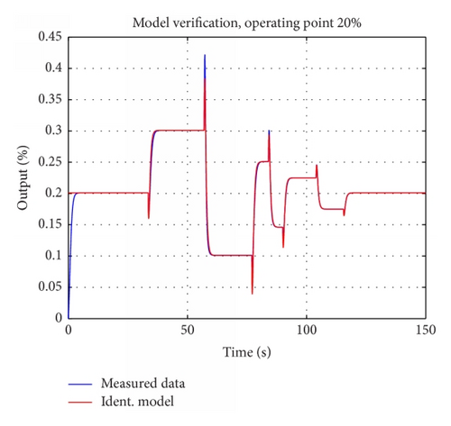
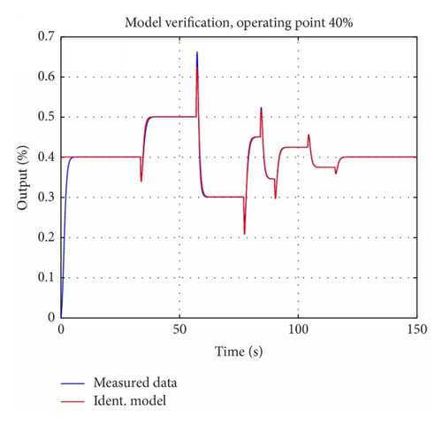
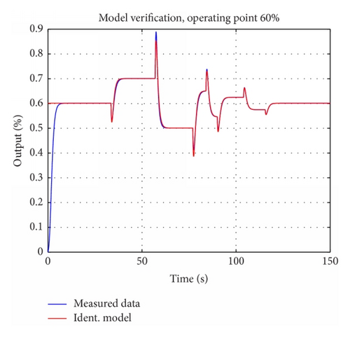
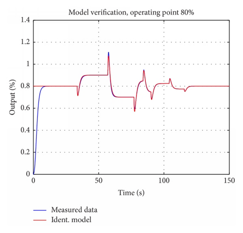
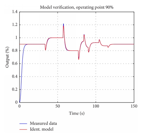
Consider hydraulic turbine with power operating range (0–100)%. In our case, nonlinear model described in [1] will be identified using input-output identification in five operating points (output power of 20%, 40%, 60%, 80%, and 90%). As identification results linear models in transfer functions form will be obtained.
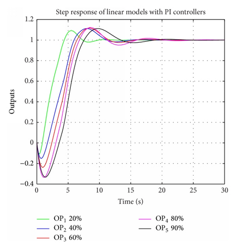
Step 1 (multimodel control). In first step, multimodel control approach will be used for hydraulic turbine control. For each transfer function, PI controller will be designed using D-partition method [9]. Aim of controller tuning will be keeping overshoot up to 10%:
Figure 7 shows that overshoot condition is satisfied for all linear models (operating points). On the nonlinear system, two different switching algorithms will be tested.
First switching algorithm will be based on system output. Since system output will be lower than 30%, first controller will be active. If output will be more than 30% but less than 50%, second controller will be active and so on (Table 1).
| Output [%] | <0, 30) | <30, 50) | <50, 70) | <70, 85) | <85, 100) |
|---|---|---|---|---|---|
| Active contr. | R1(s) | R2(s) | R3(s) | R4(s) | R5(s) |
In each sample time comparison will be done and Ri(s) controller will be set as active,
where i ∈ q is index of model with smallest J (20).
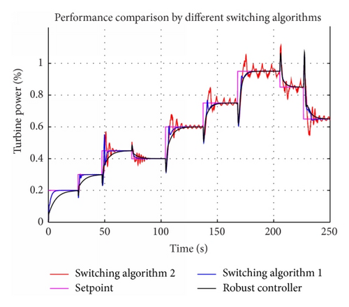
Nonlinear turbine model has strong nonminimal phase behavior. Performance comparison (Figure 8) by different switching algorithms shows that switching speed has significant influence on performance. First switching algorithm is slow and by second algorithm switching is very fast (Figure 9).
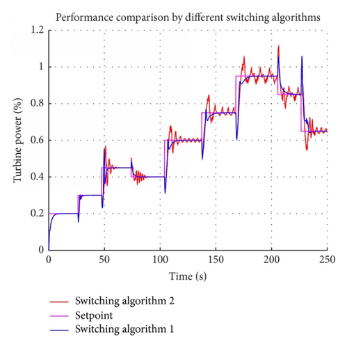
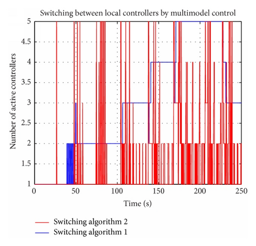
When high control performance is needed, it is recommended to avoid fast switching. Possible solutions could be increasing switching period (not at each sample time), weighting of controller outputs, or, in this case, using first switching algorithm.
Step 2 (robust control). In second step by robust control design instructions from previous chapter will be used.
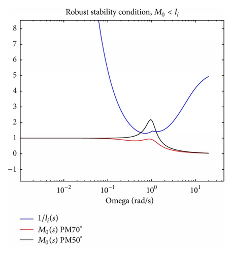
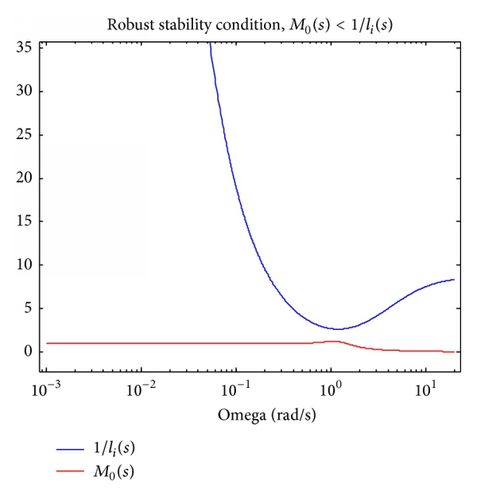
For nominal model, PI controller was calculated using design method ensuring desired phase margin. Controller ensuring phase margin PM = 50° does not guarantee robust stability condition, because desired phase margin was increased to PM = 70° (Figure 10).
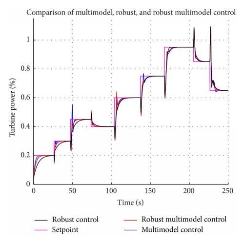
Comparison of multimodel and robust control (Figure 11) shows slower response of system with robust control in lower power output. By higher power output, system response with robust control is similar to system response with multimodel control. Performance of control approaches will be compared also numerically in Table 2, using IAE criterion.
| Control | Multimodel 1 | Multimodel 2 | Robust |
|---|---|---|---|
| IAE | 4,82 | 7,06 | 5,94 |
Step 3 (robust multimodel control). In third step, robust multimodel control will be designed, which is a combination of robust and multimodel control (see Table 4).
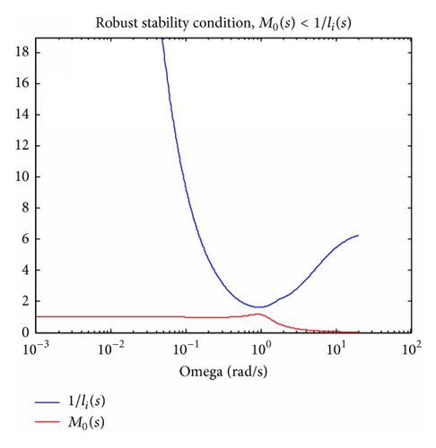
Robust stability condition (Figure 12) proves robust properties of designed controller. From behaviour of M0(s) (in Figures 10 and 12), it is obvious that that robust multimodel control is less conservative as pure robust control.
Robust stability condition (Figure 13) proves robust properties of designed controller.
Comparison of three control approaches (Figure 14) shows that robust multimodel control is almost so fast as multimodel control. Performance of multimodel, robust, and robust multimodel control is compared in Table 3 by first switching algorithm (described in Table 1).
| Control | Multimodel 1 | Robust | Multimodel robust |
|---|---|---|---|
| IAE | 4,82 | 5,94 | 4,92 |
| Control algorithm 2 | Multimodel | Robust multimodel |
|---|---|---|
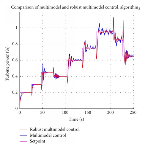
| IAE | 7,06 | 5,7 |
Performance of multimodel and robust multimodel approaches will be compared also using second switching algorithm (Figure 15). Robust properties improved performance by this fast switching algorithm.
5. Conclusion
In this paper, hybrid control, often denoted by multimodel control, was used. Two switching algorithms were compared to show how the switching speed affects performance and stability. Robust control method based on M − Δ was presented as a control solution which ensures stability on whole operating range, but with lower performance. Combination of multimodel control and robust control which ensure stability and good performance was illustrated on nonlinear hydraulic turbine model. Designed control solution is less conservative as robust control but stable on whole operating range and almost with the same performance as using multimodel control.
Conflict of Interests
The authors declare that there is no conflict of interests regarding the publication of this paper.
Acknowledgment
This work was supported by the Scientific Grant APVV 0772-12.
Appendix
For identification results, in form of model verification, in all operating points , see Figures 16-19–20.


