Investigation of CO2 Enhanced Oil Recovery Using Dimensionless Groups in Wettability Modified Chalk and Sandstone Rocks
Abstract
The paper addresses enhanced oil recovery in chalk and sandstone rocks by CO2 injection, with different wettability, porosity, and permeability as well as injection rate and flooding conditions. Results indicate that an increase in Bond number has a positive effect on oil recovery whereas for capillary number, there is a limit in which recovery is improving. This limit is estimated when the pressure drop by viscous force is approximately equal to the threshold balance between capillary and gravity forces. A dimensionless group is proposed that combines the effect of capillarity, injection rate, permeability, and CO2 diffusion on the oil recovery. Recovery from all experiments in this study and reported data in the literature shows a satisfactory relationship with the proposed group.
1. Introduction
CO2 flooding is the most widely used method for medium and light oil recovery in sandstone and carbonate reservoirs during the last decades [1, 2]. In the past five decades, there have been extensive laboratory studies, numerical simulations, and field applications of CO2 EOR processes [1, 3–6]. The mechanisms affecting the displacement of oil by CO2 injection include oil swelling, IFT (interfacial tension), and viscosity reduction as well as increasing the injectivity index due to solubility of CO2 in water and subsequent reaction of carbonic acid with the minerals [7–9]. For immiscible CO2 flow in porous media, displacement efficiency could depend on the wetting properties of the fluids, the rate of CO2 injection and oil production, the difference of oil and CO2 density, the viscosity ratio of fluids, and the oil and CO2 relative permabilities [7]. Miscible CO2 EOR reduces viscosity and CO2 can vaporize and extract intermediate hydrocarbons from the reservoir crude oil and/or condense to the oil for developing miscibility under certain pressures and temperatures [10]. Displacement efficiency for miscible CO2 flooding is also influenced by wetting properties of the rock, injection and production rates, density difference between oil and gas, viscosity ratio of fluids, and oil/CO2 relative permabilities [10].
Investigations in the laboratories and in the field [11–18] suggest the importance of the gas-oil gravity segregation in CO2 EOR. Kulkarni and Rao [16] presented the effect of important dimensionless groups on the final oil recovery obtained from a number of miscible and immiscible CO2 gravity drainage experiments. They stated that the main design parameters on a laboratory scale to evaluate the feasibility of gas injection depend on reservoir heterogeneity, rock type, fluid characteristics, injection gas, WAG ratio, and gravity considerations as well as miscibility development and compositions of oil and brine [16]. Wood et al. [19] introduced ten dimensionless groups to describe CO2 flooding in a dipping water flooded reservoir and used them for experimental design purposes to develop screening criteria applicable to Gulf Coast reservoirs. Trivedi and Babadagli [20] proposed a new group incorporating the matrix-fracture diffusion transfer for scaling of the miscible displacement in fractured porous media.
The objective of this paper is to study CO2 enhanced oil recovery in chalk and sandstone rocks. The wettability of calcite and silicate minerals has been changed using fatty acid (stearic acid), amine (N,N dimethyldodecylamine), and asphaltene dissolved in the base solvents. A number of CO2 flood experiments are performed with various ranges of permeability, porosity, wetting state, and CO2 injection pressure and rate. These parameters are changed extensively to obtain a wide range of dimensionless groups. The results have been analyzed using capillary, Bond, and diffusion numbers at different wetting states. A new dimensionless group is proposed that combines the effect of capillarity, injection rate, permeability, and CO2 diffusion during flooding processes.
2. Theory
3. Experimental Section
3.1. Materials
3.1.1. Solid Phase
The core flood experiments were done in outcrop Stevns klint chalks near Copenhagen and outcrop Benthiemer sandstones. The dimension of cores varied between 5–7 cm in length and 3.8 cm in diameter. The out crop chalks have approximate porosity of 44–48% and absolute permeability of 3–7 mD. Sandstone cores have the same porosity near 22–25%, while they are classified based on the permeability in the two groups with permeability range of 600–800 mD and with the permeability range of 1500–1700 mD. The capillary threshold of chalk cores for oil and gas system is measured near 2 bar by porous plate technique. The capillary threshold of Benthiemer sandstones was reported as 0.05 atm [29]. Table 1 is the cores detailed descriptions.
| EXP. number | Swi | Phi | K (cm2) | L (cm) | q (cc/min) | Type | Core |
|---|---|---|---|---|---|---|---|
| 1a | 0.22 | 0.23 | 6.5E − 09 | 6 | 0.2 | Immiscible | Aged sandstone |
| 2a | 0.2 | 0.24 | 7.5E − 09 | 5.5 | 0.5 | Immiscible | Aged sandstone |
| 3a | 0.25 | 0.25 | 7.3E − 09 | 5.8 | 2 | Immiscible | Aged sandstone |
| 4a | 0.2 | 0.25 | 8.3E − 09 | 6.2 | 6 | Immiscible | Aged sandstone |
| 5a | 0.25 | 0.23 | 6.7E − 09 | 6 | 8 | Immiscible | Aged sandstone |
| 5a* | 0.21 | 0.22 | 6E − 09 | 5.5 | 8 | Immiscible | Aged sandstone |
| 5a** | 0.22 | 0.24 | 7.6E − 09 | 6 | 8 | Immiscible | Aged sandstone |
| 1b | 0.2 | 0.23 | 1.5E − 08 | 6 | 0.5 | Immiscible | Aged sandstone |
| 2b | 0.25 | 0.24 | 1.6E − 08 | 5.5 | 2 | Immiscible | Aged sandstone |
| 3b | 0.22 | 0.24 | 1.7E − 08 | 5.5 | 8 | Immiscible | Aged sandstone |
| 4b | 0.25 | 0.25 | 1.7E − 08 | 5.8 | 10 | Immiscible | Aged sandstone |
| 1c | 0.14 | 0.44 | 5E − 11 | 6 | 0.2 | Immiscible | Aged chalk |
| 2c | 0.15 | 0.45 | 3.5E − 11 | 6.5 | 0.5 | Immiscible | Aged chalk |
| 3c | 0.12 | 0.48 | 6E − 11 | 6.7 | 2 | Immiscible | Aged chalk |
| 4c | 0.13 | 0.47 | 5.5E − 11 | 5.8 | 2.5 | Immiscible | Aged chalk |
| 5c | 0.1 | 0.48 | 6.5E − 11 | 5.9 | 3.5 | Immiscible | Aged chalk |
| 5c* | 0.13 | 0.45 | 6.2E − 11 | 6.5 | 3.5 | Immiscible | Aged chalk |
| 5c** | 0.15 | 0.47 | 6E − 11 | 6 | 3.5 | Immiscible | Aged chalk |
| 1d | 0.17 | 0.44 | 5.5E − 11 | 6 | 0.01 | Immiscible | Aged chalk |
| 2d | 0.15 | 0.45 | 4E − 11 | 6.5 | 0.05 | Immiscible | Aged chalk |
| 3d | 0.11 | 0.48 | 2E − 11 | 6.7 | 0.1 | Immiscible | Aged chalk |
| 1e# | 0.16 | 0.45 | 6.5E − 11 | 6 | 0.05 | Miscible | Aged chalk |
| 2e# | 0.14 | 0.46 | 4E − 11 | 6.5 | 0.05 | Miscible | Aged chalk |
| 3e# | 0.12 | 0.48 | 2.5E − 11 | 6.8 | 0.05 | Miscible | Aged chalk |
| 1e | 0.27 | 0.25 | 6.5E − 09 | 6 | 0.05 | Miscible | Unaged sandstone |
| 2e | 0.3 | 0.23 | 7.7E − 09 | 6.5 | 0.05 | Miscible | Unaged sandstone |
| 3e | 0.125 | 0.22 | 8.2E − 09 | 6.8 | 0.05 | Miscible | Unaged sandstone |
| 1g | 0.22 | 0.23 | 1.8E − 08 | 6 | 0.5 | Immiscible | Unaged sandstone |
| 2g | 0.23 | 0.26 | 1.9E − 08 | 5.5 | 2 | Immiscible | Unaged sandstone |
| 3g | 0.24 | 0.3 | 2.1E − 08 | 5.5 | 8 | Immiscible | Unaged sandstone |
| 4g | 0.24 | 0.25 | 1.8E − 08 | 5.8 | 10 | Immiscible | Unaged sandstone |
| 1h | 0.14 | 0.44 | 5.5E − 11 | 6 | 0.05 | Miscible | Unaged chalk |
| 2h | 0.15 | 0.45 | 5.5E − 11 | 6.5 | 0.05 | Miscible | Unaged chalk |
| 3h | 0.17 | 0.47 | 6E − 11 | 6.8 | 0.05 | Miscible | Unaged chalk |
- *Repetition of experiment (first time).
- **Repetition of experiments (second times).
- #Previously reported in Hamouda, A.A., Alipour Tabrizy, V., 2013, the effect of light gas on miscible CO2 flooding to enhance oil recovery from sandstone and chalk reservoir, and journal of Petroleum Science and Engineering, volume 108, pages 259–266.
3.1.2. Oil Phase
The investigation is done for model oil containing asphaltene dissolved in toluene (95% purity), 0.01 M stearic acid (SA) dissolved in n-decane (95% purity) for chalk cores, and 0.01 M N,N-dimethyldodecylamine (NN-DMDA) dissolved in n-decane (95% purity) for sandstone cores. Synthetic seawater (SSW) has been used as irreducible water saturation. Tables 2 and 3 show the polar components used in this work and also the ionic composition of synthetic seawater.
| Components | Supplier and purity | Structural formula |
|---|---|---|
| Stearic acid (SA) | Aldrich ≥99% | CH3(CH2)16COOH |
| N,N-dimethyldodecylamine (NN-DMDA) | Fulka ≥99% | CH3(CH2)11N(CH3)2 |
| Ions | Concentration (mol/L) |
|---|---|
| NaCl | 0.4 |
| KCl | 0.01 |
| CaCl2(2H20) | 0.013 |
| MgCl2(6H20) | 0.045 |
| NaHCO3 | 0.002 |
| Na2(SO4) | 0.024 |
| TDS | 0.494 |
3.1.3. Asphaltene Preparation Procedure
The model oil system is prepared from asphaltene precipitated from crude oil in excess of n-heptane (1 : 40). The mixture was shaken for at least twice a day and left for 48 hours to equilibrate. The mixture solution was then centrifuged and filtered through a 0.22 micrometer filter (Millipore) and dried for 1 day using a vacuum oven at room temperature. The dried asphaltene was then dissolved in toluene.
3.2. Experimental Setup
The detailed description of the experimental set up has been addressed elsewhere [30]. The major components of the experimental setup consist of a core holder, pressure regulators, two gas flow meters, pressure manometers, Gilson pump, CO2 piston cell, graduated gas/oil separator, and a lab view version 7.1 connected to a digital data acquisition system. Saturated core samples with synthetic seawater were inserted into a horizontally placed core holder that consists of a steel cylindrical body and rubber/nylon sleeve. A net overburden pressure of 20 bar is applied on the sleeve. The chalk core is flooded with oil sample at flow rate of 0.1 mL/min until oil breakthrough is occurred and then it is increased to 5 mL/min to overcome the capillary threshold using Gilson pump (806 manometric modules) to establish the irreducible water. The sandstone core is flooded with oil sample at flow rate of 3 mL/min until oil breakthrough is occurred and then it is increased to 5 mL/min to overcome the capillary threshold. Table 1 shows the irreducible water saturation, which is varying between 10 and 13% for chalks and 20 and 25% for sandstones. The cores were aged for at least two weeks to change the wettability of cores toward oil wet, when the saturating oil contains polar components. Then, CO2 injection was carried out in two modes, namely, injection at constant rate and constant pressure. At constant rate, CO2 is injected from piston connected to Gilson pump (806 manometric modules) with desired rate. At constant pressure modes, CO2 is injected in immiscible and miscible processes. In the immiscible process, the pressure of CO2 injection is lower than minimum miscibility pressure. Whereas, in the miscible mode, the oil saturated core was flooded with CO2 at pressure equal to minimum miscibility pressure. CO2 was injected into the core at constant pressures of 40 ± 0.2 bar and temperature of 25°C for immiscible process and 90, 70, and 140 ± 0.2 bar and at 50, 70, and 80°C for miscible processes. The constant pressure of CO2 is provided by Gilson pump when the upper and lower pressure limits of pump are adjusted to the desired injection pressure plus/minus 0.5 bar. CO2 is injected to the core passing mass flow meter (1) that records the inflow properties of CO2 (mass flow rate, density, and total mass). A back pressure regulator is connected downstream the core to control the pressure during CO2 flooding. The outflow properties (mass flow rate, density, and total mass) of the evolved gas were, also, recorded using flow meter (2) connected to the separator. The CO2 injection continued for at least 3 pore volumes until there was no oil production. When the injection was terminated, the core was then removed from the core holder and dried using vacuum oven at a temperature of 120°C until a constant weight was obtained.
4. Results and Discussion
The experimental results with the relation to the selected dimensionless groups are discussed in this section.
4.1. Bond Number
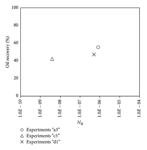
The variations in Bond number were primarily performed by varying the permeability of the porous medium, where reduction in permeability leads to a reduction in Bond number. As it is seen in (2), permeability does not affect the capillary number, thus allowing investigation of the effect of Bond number on the oil recovery at a constant capillary number. Recovery factor after two pore volumes of injected CO2 as a function of the Bound number is shown in Figure 1. Results indicate that recovery at a constant capillary number increases with increasing the Bond number. This behavior is in line with the expectation about the effect of capillarity on oil drainage by gas injection. To examine the relationship between oil recovery and Bond number, the recovery between all experiments is plotted versus Bond numbers in Figure 2. No satisfactory relation was found between the oil recovery and the balance between gravity and capillary forces.
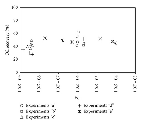
The scaling of oil recovery using Bond number has three major limitations: (I) the effect of viscous force is not included. For example, by changing the gas injection rate, the oil recovery may be changed drastically, while the Bond number is remained unchanged; (II) the effect of viscosity ratio between displaced and displacing fluids is not included. For example, when the gas/oil viscosity ratio changes leading to a change in stability of the front and recovery, the Bond number remains unchanged. The effect of CO2 diffusion in oil and miscibility parameters that is, pressure, temperature, and oil composition, are not considered also in Bond number. The effects of viscous forces, viscosity ratio, and CO2 diffusion are incorporated in the following sections.
4.2. Capillary Number
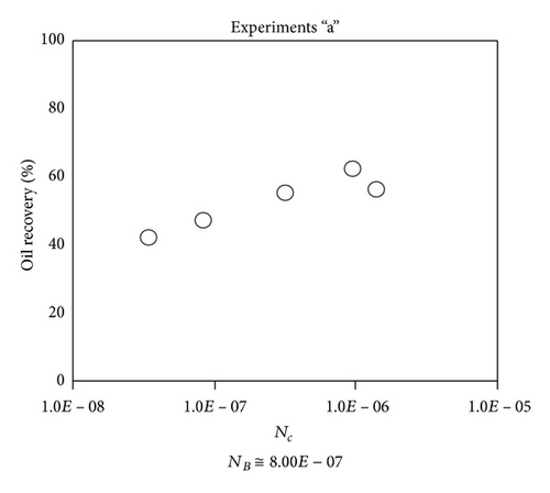
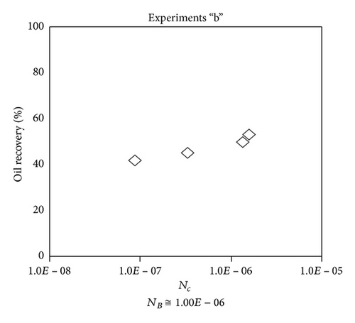
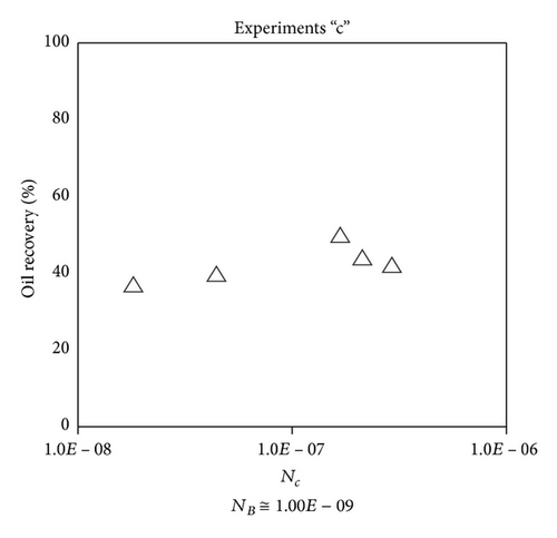
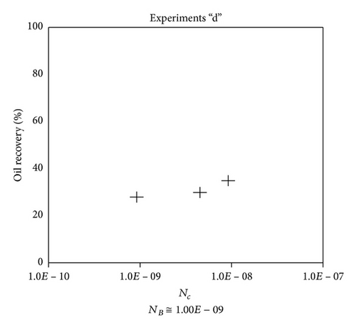
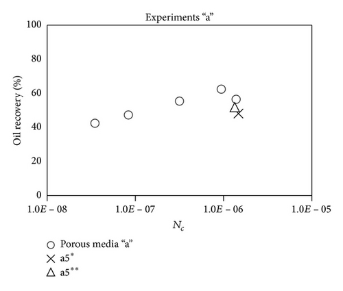
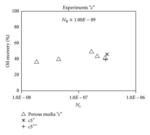
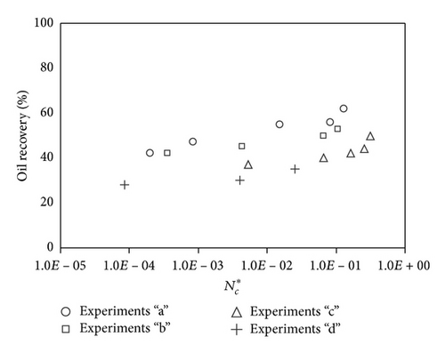
Large viscous forces in high-rate gas flooding, characterized by large capillary numbers, may result in unstable flooding fronts and the oil bypassing/trapping mechanism. From this point of view, an increase in the viscous force will result in reduction in the oil recovery because the microscopic displacement efficiency decreases. However, the low-rate gas flooding may lead to considerable residual oil since the pressure drop across the core may be lower than the capillary threshold. In the work reported by Rostami et al. [31], it has been observed that in unconsolidated bead pack porous media and high permeable water-wet outcrop sandstones, the oil recovery reduces as capillary number increases. This may not be applicable in the real reservoir cores, especially for tight oil-wet carbonate rocks with considerable capillary threshold. Experimental results are shown in Figure 4(a) to Figure 5(d), where oil recovery after two-pore volume CO2 injection is plotted versus capillary number. Results in each figure are characterized by a Bond number that remains approximately constant. The interfacial tension between CO2 and oil is estimated near to 20 mN/m for immiscible process and 0.1 mN/m for miscible process according to (3). Results indicate that oil recovery improves as capillary number increases up to the critical limit where afterward decreases. In other words, the recovery increases when the pressure drop due to viscous force increases near to the capillary threshold and then decreases due to flow instability. From Figure 3, it is clear that for experiments “a” and “c,” the oil recovery is increasing up to a certain value and then it is decreasing by increasing the injection rate and viscous force. The maximum oil recovery may be linked to the pressure drop in which . To observe the reliability of results, experiment “a5” and experiment “c5” are repeated and they are shown in Figure 4. The variations of oil recovery for similar conditions are near to 5%.
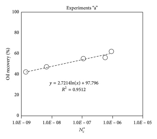
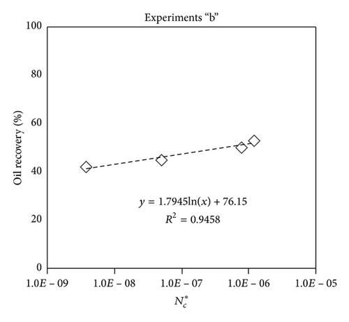
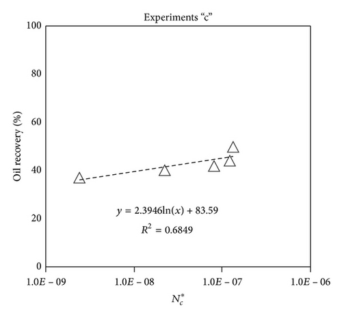
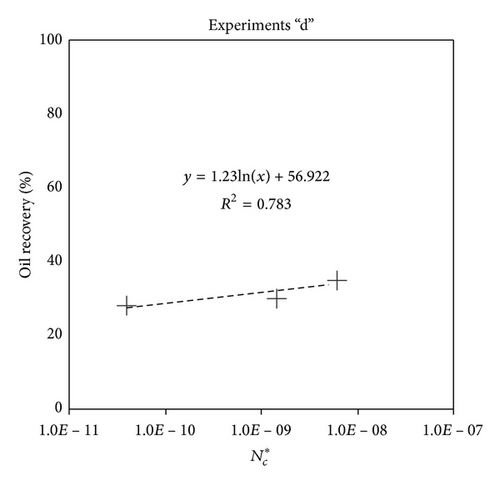
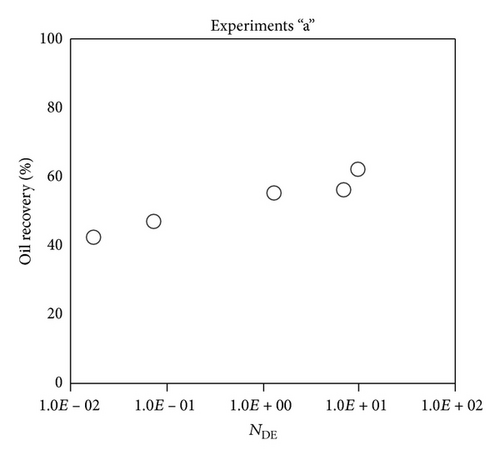
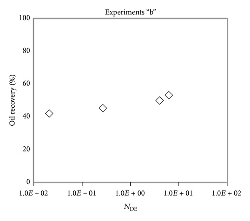
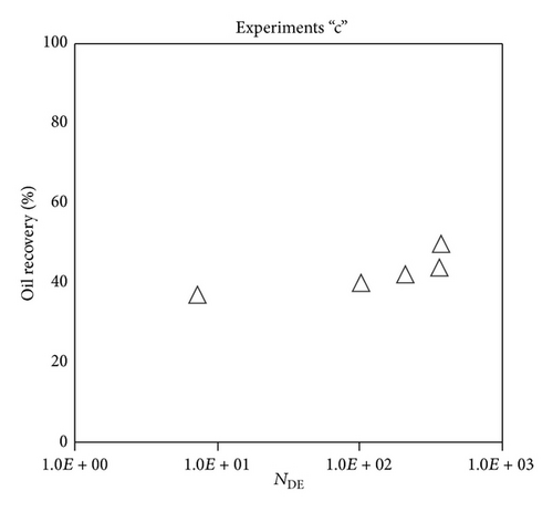
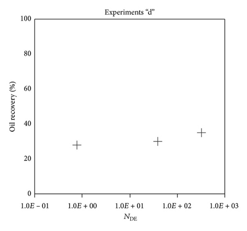
To explore an appropriate dimensionless number that describes the dynamics of the oil recovery, recoveries from all experiments are plotted versus their modified capillary numbers (Figure 7). Again, no satisfactory relation is observed. This confirms that the capillary number alone is insufficient to predict the oil recovery behavior during the CO2 flooding.
4.3. Diffusion Number
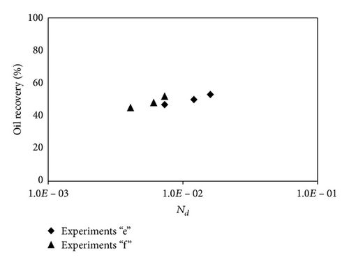
Diffusion number expresses the ratio of diffusivity to convective dispersion (bulk flow or viscous force). The number is important in miscible processes, when the diffusion of solvent in oil is considerable and the oil production is slow; hence, the viscous force and convective dispersion are small and the diffusion number should be taken into account according to (6). Experiments in porous media “e” and “f” are done in miscible mode in chalk and sandstone cores, respectively. The minimum miscible pressure (MMP) for model oil composition at different temperatures is calculated according to SRK-Peneloux EOS, PVTsim version 17. The oil recovery for miscible CO2 flooding experiments for porous media “e” and “f” is shown in Figure 8. The CO2 flooding has been done at 50°C, 70°C, and 90°C and pressures 90 bar, 120 bar, and 140 bar for experiments “e1,” “f1,” “e2,” “f2,” “e3,” and “f3,” respectively. Form the graph, it can be seen that as temperature and pressure are increasing, the diffusion number (Nd) increases and the recovery by CO2 flooding is increasing. It is important to mention that the oil recovery rate before CO2 breakthrough is kept near 0.05 cc/min for all experiments; accordingly the viscous force and capillary number of miscible experiments are small (Nc≅10−7) and close to each other.
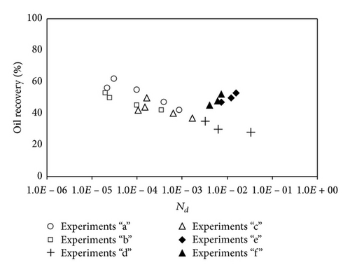
The dependency of all miscible and immiscible experiments to diffusion number is shown in Figure 9. As it can be seen, no relation could be drawn down for results, since the diffusion number is not playing a critical major role in all experiments.
4.4. Combined Dimensionless Group
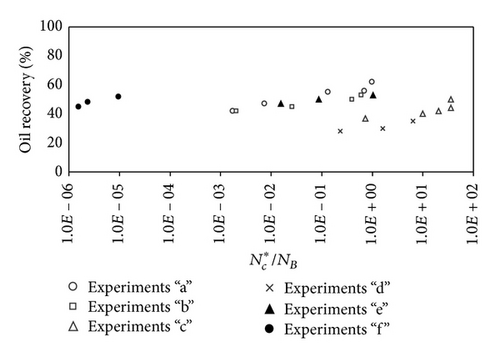
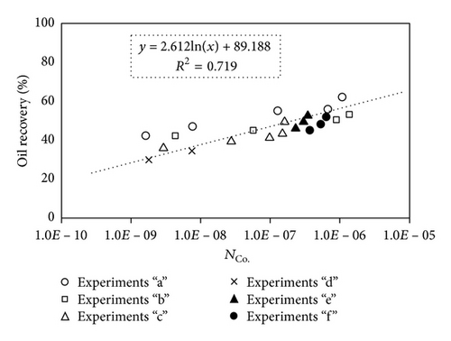
Examination of oil recoveries as a function of dimensionless numbers (capillary number, Bond number, modified capillary number, and diffusion number) suggests that none of the above scaling groups individually can define the oil recovery relationship to affecting parameters. In the following section, a combined dimensionless group that could show the relationship of oil displacement over the whole range of variables is investigated. Figure 10 shows the results of all experiments, when ratio of the modified capillary number over Bond number is used. Results indicate that the oil recovery by CO2 flooding is directly proportional to the ratio of modified capillary number over Bond number; however, no specific relation may explain this relationship.
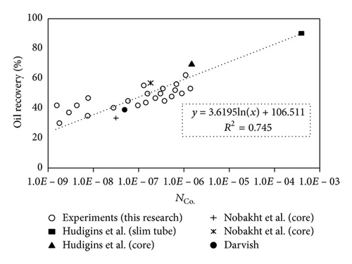
In order to validate the applicability of the new group proposed for gas injection processes, the experimental results reported by Hudigins et al., (1990), Darvish [23], and Nobakht et al. [22] are used. Table 4 summarizes the properties of literature experimental data used in this study.
| Number | Type | Swi | Phi | K (cm2) | L (cm) | q (cc/min) | σ gas oil (mN/m) |
Reference |
|---|---|---|---|---|---|---|---|---|
| 11 |
|
0 | 0.379 | 1.2E − 07 | 2720 | 4.76 | 0.1 | Hudgins et al. [21] |
| 21 |
|
0.4 | 0.198 | 4.6E − 09 | 60.96 | 0.8 | 0.1 | Hudgins et al. [21] |
| 31 |
|
0.07 | 0.372 | 1.8E − 05 | 28.8 | 0.5 | 4.22 | Nobakht et al. [22] |
| 41 |
|
0.025 | 0.369 | 1.8E − 05 | 28.8 | 0.5 | 1.13 | Nobakht et al. [22] |
| 51 |
|
0 | 0.444 | 4E − 11 | 60 | 0.02 | 0.05 | Darvish (2007) [23] |
The first two experimental data are related to miscible N2 injection in the slim tube and core, respectively; hence, the diffusion number and other relevant parameters are calculated for nitrogen. The third and fourth experiments were done for miscible CO2 flooding in sandstone cores and the fifth experiment was reported for CO2 flooding in saturated chalk core with live reservoir oil. Figure 12 compares the experimental data reported in this research and literature data reported previously.
4.5. Effect of Wettability
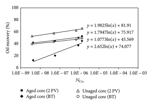
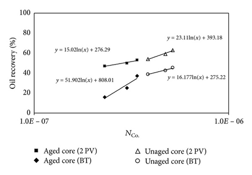
Figure 14 shows that the oil recoveries after 2 PV of injected CO2 for unaged samples are higher than the aged samples. Similar trend to immiscible CO2 flooding can be seen for miscible CO2 flooding.
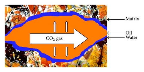
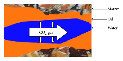
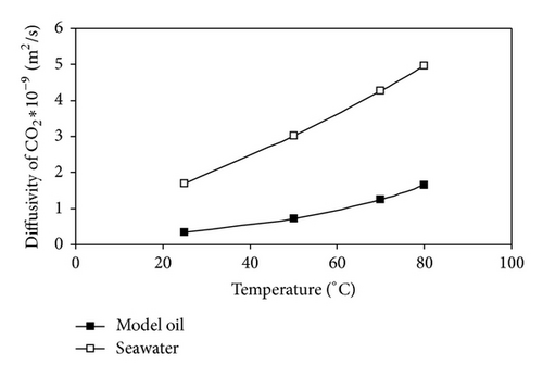
In unaged core (water-wet porous media), water is not mobilized and wets the pore walls and oil is maintained in the center of pores; hence, the CO2 diffuses to oil and the recoveries at CO2 breakthrough and 2 PV injected CO2 are higher than aged core. In aged core (oil wet), the water droplet occupies the center of pore and the injected CO2 will dissolve in water and then the mass transfer between oil and CO2 may occur; hence, the water will act as a barrier. Figure 15 shows the schematic of CO2 enhanced oil recovery in hydrophobic (aged) and hydrophilic (unaged) porous media. In this figure, oil is shown by brown; water is shown by blue and CO2 is represented by white color.
5. Conclusion
Analysis of oil recovery with Bond number, at constant capillary number, shows a direct relation, but when the capillary number is changing, dependency of oil recovery with the Bond number is varying also. In addition, at constant Bond number, oil recovery increases as capillary number increases up to a certain limit and then decreases drastically as a result of higher viscous forces and fluid flow instability. Results presented in this work suggest that the Bond, capillary, and diffusion numbers could not scale the oil recovery, individually. A dimensionless group was defined to relate the competition between three forces affecting oil recovery over a wide range of petrophysical and experimental conditions. A logarithmic relationship was observed between the proposed group and oil recovery. Applicability of the proposed relation beyond the range of experiments reported in this work needs to be further examined. It is observed also that the recovery by CO2 injection for unaged rocks (water wet) is higher than the aged (oil wet) rocks due to higher diffusivity of CO2 in water (occupying the center of pores in oil-wet cores) compared to that in oil.
Nomenclature
-
- A:
-
- Cross-sectional area
-
- So:
-
- Oil saturation
-
- Sg:
-
- Gas saturation
-
- S:
-
- Saturation
-
- Si:
-
- Initial water saturation
-
- Swi:
-
- Irreducible water saturation
-
- SOD:
-
- Dimensionless saturation
-
- φ:
-
- Porosity
-
- μ:
-
- Viscosity
-
- ρ:
-
- Density
-
- q:
-
- Injection rate, volumetric flux
-
- qc:
-
- Vertical flow rate
-
- P:
-
- Capillary pressure/parachor confident
-
- Pc:
-
- Pressure
-
- :
-
- Threshold pressure
-
- tDg:
-
- Dimensionless time
-
- Nc:
-
- Capillary number
-
- Ng:
-
- Gravity number
-
- Nb:
-
- Bond number
-
- Nd:
-
- Diffuision number
-
- NCO.:
-
- Combined number
-
- NDE:
-
- Displacement efficiency number
-
- Kromax:
-
- End point oil permeability
-
- Krgmax:
-
- End point gas permeability
-
- Kr:
-
- Relative permeability
-
- Kro:
-
- Relative oil permeability
-
- Krg:
-
- Relative gas permeability
-
- ng:
-
- Corey exponent in gas relative permeability function
-
- no:
-
- Corey exponent in oil relative permeability function
-
- σ:
-
- Interfacial tension
-
- S:
-
- Spreading coefficient
-
- R:
-
- Recovery factor
-
- M:
-
- Mobility ratio
-
- PV:
-
- Pore volume
-
- l:
-
- Length or height.
Subscripts
-
- g:
-
- Gas
-
- w:
-
- Water
-
- o:
-
- Oil
-
- abs:
-
- Absolute
-
- wg:
-
- Water-gas system
-
- wo:
-
- Water-oil system
-
- og:
-
- Oil-gas system.
Conflict of Interests
The author declares that there is no conflict of interests regarding the publishing of this paper. The paper will not reflect the viewpoints of the affiliated institutions by any means.
Acknowledgments
The author wish to thank the University of Stavanger for the financial support, K. P. Dziadosz and Professor Hamouda for their comments/advices in the experimental lab works, and Svein Myrhen for Lab view support and Inger Johanne for her positive contribution in getting the chemicals used in this work. This research paper is lovingly dedicated to author’s parents who have been constant source of inspiration. At time of publication of this paper, author’s father (Ibrahim Alipour Tabrizy) sadly passed away. The author never forgets his moral love and supports which without it, this research would not have been made possible.
Appendix
The boundary and initial conditions for (A.7) are as follows.
Initial Condition. S(z, 0) = 1.0 − Swi.


