Initiating a Mathematical Model for Prediction of 6-DOF Motion of Planing Crafts in Regular Waves
Abstract
Nowadays, most of the dynamic research on planing ships has been directed towards analyzing the ships motions in either 3-DOF (degrees of freedom) mode in the longitudinal vertical plane or in 3-DOF or 4-DOF mode in the lateral vertical plane. For this reason, the current authors have started a research program of describing the dynamic behavior of planing ships in a 6-DOF mathematical model. This program includes the developing of a 6-DOF computer simulation program in the time domain. This type of simulation can be used for predicting the response of these planing vessels to the environmental disturbances during high-speed sailing. In this paper, the development of the mathematical model will be presented. Furthermore, a discussion will be offered about the use of these static contributions in a time domain simulation for modeling the behavior of planing crafts in regular waves.
1. Introduction
Prediction of planing craft motion is one of the main computational challenges in marine engineering. Due to the involved computational time, computational fluid dynamics is very expensive. Experimental works are also very costly. Therefore, several researchers have tried to present mathematical models which are very easy and economical. In the last decades, two branches of mathematical models have been developed which are in two or three degrees of freedom. First branch was developed by Savitsky [1]. Savitsky’s model has not been developed extensively. For example, it cannot be applied to the planing motion in irregular waves, and it is also difficult to use it to obtain time domain simulation. However, second branch which was developed by Martin [2] has been implemented by many authors. In reality, Martin’s [2] model was in frequency domain. Zarnick [3] worked on this model and performed time domain calculations. Later, Zarnick [4] developed Martin’s model even further for planing craft motion in irregular waves. He compared his results with the experimental findings of Fridsma [5, 6] and found his model to be in favorable agreement with the experimental data. However, Zarnick’s model had some restrictions which had been resolved by some researchers. In fact, after several decades, a model which was initially developed by Zarnick is still a reliable tool for planing craft motion.
Keuning [7] extended Zarnick’s [3, 4] model to incorporate a formulation for the sinkage and trim of the ship at high speeds. He also studied the hydrodynamic lift distribution along the length of the ship with nonlinear added mass and wave exciting force in both regular and irregular waves. Hicks et al. [8] expanded the full nonlinear force and moment equations of Zarnick [3, 4] in a multivariable Taylor series. They replaced equations of motion by a set of highly coupled constant-coefficient ordinary differential equations, valid through third order. Akers [9] summarized the semi-empirical method, three-dimensional panel method, and their advantages and drawbacks dealing with planing hull motion analysis. He reviewed in detail the two-dimensional low aspect ratio strip theory developed by Zarnick [3, 4]. Akers [9] modeled the added mass coefficients based on an empirical formula that is a function of deadrise angle. Garme and Rosén [10] presented a similar time domain analysis of simulating a planing hull in head seas, which is different from the classical Zarnick’s model in precalculation scheme of hydrostatic and hydrodynamic coefficients.
Later, Grame and Rosen [11] improved his model by adding a reduction function based on model tests and published model data for the near-transom pressure. This reduced the pressure near the stem gradually to zero at the stem. van Dayzen [12] extended the original model developed by Zarnick [3, 4] and later extended by Keuning [7] to three degrees of freedom of surge, heave, and pitch motion in both regular and irregular head seas. The simulations can be carried out with either a constant forward speed or constant thrust. He also validated the results by experimental data of two models and found his model very sensitive to the hull geometry. More recently, Sebastianii et al. [13] developed previous studies to combine the roll, heave, and pitch degrees of freedom.
In the current paper, a mathematical model based on the models of Zarnick [3] and Sebastianii et al. [13] is developed. In all previous studies, 2d + t theory based symmetric wedge water entry has been used. However, the present paper tries to develop a mathematical model based on asymmetric wedge water entry which leads to various forces and moments. Actually, this mathematical model can be considered as a first step in extending Zarnick’s model to six degrees of freedom, and the authors are well aware of the fact that this mathematical model must be gradually modified, step by step.
2. Equations of Motions
3. 2d + t Theory
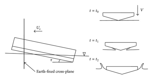
In a ship-fixed coordinate system, 2.5D theory means that the two-dimensional equations are solved together with three-dimensional free surface conditions. If the attention is focused on an Earth-fixed cross-plane, one will see a time-dependent problem in 2D cross-plane, when the vessel is passing through it. Accordingly, the theory is also called 2d + t theory. In an Earth-fixed coordinate system, a prismatic planing vessel of trim angle τ (up to 20 degrees) is moving through an Earth-fixed cross-plane with speed Us, as shown in Figure 1. At time t = t0, the cross-section is just above the free surface; at time t = t1 the cross-section is penetrating the free surface; and at time t = t2, flow separates from the chine line. Therefore, one can see a process where a V-shaped section enters the water surface in this cross-plane by a speed of V = Usτ. However, it must be noted that the developed mathematical model has some limitation, especially at high speed. Trim angle cannot exceed 20 degrees, and the wavelength must also be larger than the hull length.
- (i)
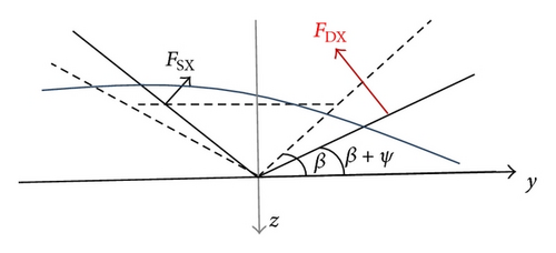
Nonsymmetrical action of fluid on boat: the boat in oblique sea undergoes different actions of fluid in its port and starboard side, due to different absolute wave velocities and relative boat motions relevant to roll.
- (ii)
Nonsymmetry of the section impacting against water: due to roll motion, the section which impacts against water is not symmetrical; starboard and port sides are considered separately with their “equivalent deadrise angle”, which is the resultant of the local geometrical deadrise and the roll angle in order to compute the added mass terms.
- (iii)
Nonsymmetrical submerged volume geometry: submerged volume and wet surface are no longer symmetrical, affecting hydrostatics and in general force application points.
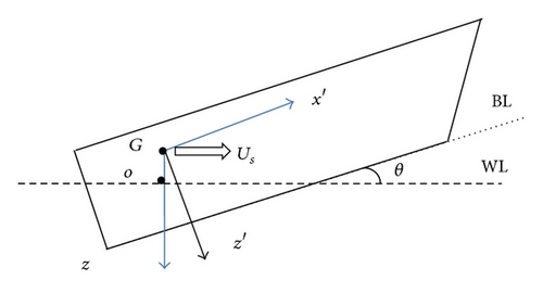
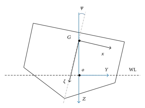
4. Regular Wave Theory
5. Force Acting on the Hull
As mentioned earlier, the numerical model employed here for prediction of planing motion utilizes a modified 2d + t theory with momentum theory. The vessel is considered to be composed of a series of 2D wedges, and the three dimensional problem is subsequently solved as a summation of the individual 2D slices. The forces acting on a cross-section consist of four components (force per unit length): the weight of the section (w), a hydrodynamic lift associated with the change of fluid momentum (fM), a viscous lift force associated with the cross flow drag (fcd) [7, 12], and a buoyancy force associated with instantaneous displaced volume (fb) [3, 12].
5.1. Momentum and Added Mass Theories
5.2. Total Hydrodynamic Force and Moment
The total hydrodynamic forces acting on the vessel are obtained by integrating sectional 2D forces over the wetted length, lw, of the craft. Force and moments in each direction are presented, separately.
5.2.1. Horizontal Force
5.2.2. Side Force
5.2.3. Vertical Force
5.2.4. Roll Moment
5.2.5. Pitch Moment
5.2.6. Yaw Moment
6. Solution of Equations of Motion
The solution of the derived equations of motion is complicated. They form a set of three coupled second-order nonlinear differential equations which has to be solved using standard numerical techniques in the time domain. The set of equations is first transformed into a set of six coupled first-order nonlinear differential equations by introducing a state vector. Subsequently, resulting equations must be solved using a numerical method such as Runge-Kutta-Merson.
Knowing the initial state variables at time instant t0, the equations are simultaneously solved for the small time increment Δt to yield the solution at t + Δt. The advantage of the Runge-Kutta-Merson method is that it is high order and it has adaptive step size control. More details can be found in many reference books like [15].
7. Validation
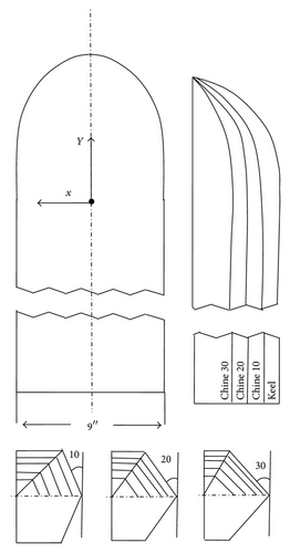
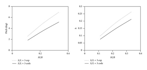
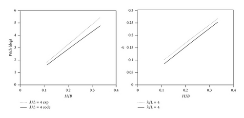
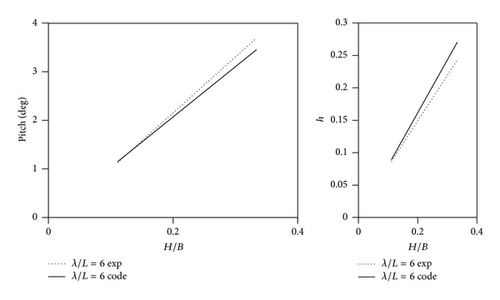
It must be denoted that, based on our knowledge, there is no experimental or numerical work on planing motion in 6 degrees of freedom. Therefore, to validate the developed mathematical model, it is reasonable to examine the basis of the developed code. For this purpose, experiments of Fridsma [5] are considered. He used a prismatic hull with 10, 20, and 30 deadrise angles in his experiments (Figure 5). Moreover, characteristics of the hull which is considered in the current study are presented in Table 1. To validate the current solutions, planing motion at both calm water and regular wave will be compared against the experiments. At first, resistance of the ship hull at calm water is obtained and compared against experiments of Fridsma, and then planing motion at regular wave for eighteen different cases is investigated at different wavelength and wave height which are presented in Table 2.
| Model | A | B |
|---|---|---|
| L/b | 5 | 5 |
| β (deg) | 20 | 20 |
| LCG (%L) | 59 | 62 |
| τ (deg) | 4 | 4 |
| V/√L | 4 | 6 |
| CΔ | 0.608 | 0.608 |
| Run conditions | |||
|---|---|---|---|
| No. | H/b | λ/L | h/H |
| 1 | 0.111 | 1 | 0.18 |
| 2 | 0.167 | 1 | 0.17 |
| 3 | 0.222 | 1 | 0.17 |
| 4 | 0.056 | 2 | 0.93 |
| 5 | 0.111 | 2 | 0.84 |
| 6 | 0.167 | 2 | 0.81 |
| 7 | 0.167 | 2 | 0.74 |
| 8 | 0.222 | 2 | 0.73 |
| 9 | 0.334 | 2 | 0.59 |
| 10 | 0.334 | 2 | 0.61 |
| 11 | 0.111 | 3 | 1.18 |
| 12 | 0.222 | 3 | 1.13 |
| 13 | 0.334 | 3 | 1.05 |
| 14 | 0.111 | 4 | 1.23 |
| 15 | 0.222 | 4 | 1.11 |
| 16 | 0.334 | 4 | 1.07 |
| 17 | 0.111 | 6 | 1.04 |
| 18 | 0.334 | 6 | 0.97 |
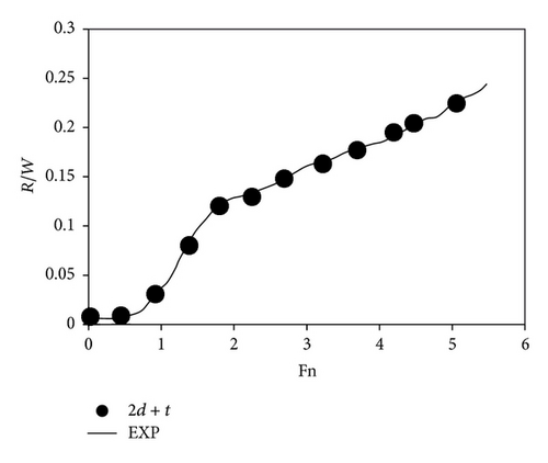
In addition to some details like the designated parameters in Table 2, more details should be considered to perform simulations. For example, ship hull is divided into 76 sections, and initial conditions are adopted based on [3, 5]. Figure 6 indicates that numerical details which are adopted in 2d + t simulations are completely in good agreement with the physical characteristics of the problem. In fact, the obtained resistance from 2d + t solutions is in excellent agreement with the experimental data. Therefore, it can be concluded that the considered setting may be suitable for future regular wave solutions.
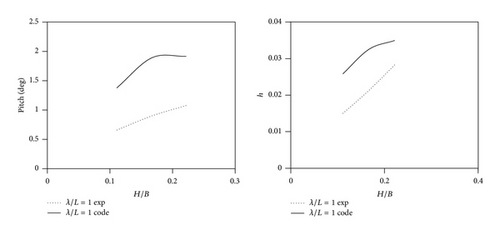
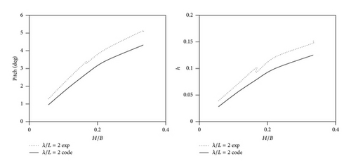
Furthermore, Figure 7 shows the obtained results for the heave and pitch motions at different H/B ratios. Details of the considered variables are reported in Table 2. It is observed that for wavelength equal to the ship length, the obtained results are not accurate, and an over prediction is seen. However, by increasing the wavelength, the results are more accurate. This can be attributed to the assumption that the wavelength must be sufficiently larger than the ship length. This assumption has been utilized in all previous studies. Overall, it can be concluded that the current mathematical model can be implemented for practical design of planing hulls seakeeping. However, it is worth mentioning that there is urgency for measuring planing craft motions (6-DOF) at regular and irregular waves as a benchmark case.
8. Results
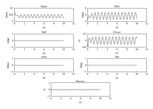
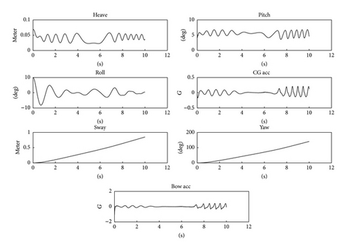
After validation, it is necessary to study the planing craft motion in six degrees of freedom in regular waves. For this purpose, cases 15 and 17 in Table 2 are considered. Ship hull is divided to 76 sections and initial condition for each degree of freedom is arbitrarily adopted. These initial values can be identified using the presented results. Moreover, three initial roll angles 0, 5, and 10 degrees are compared against each other. This means that H and λ are kept fixed (cases 15 and 17), and effects of an initial roll angle on planing craft motion are studied. Initial yaw and sway values are also kept to be zero. It must be mentioned that the main purpose of these simulations is the examination of the developed mathematical model.
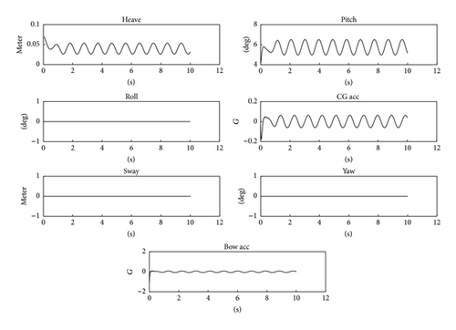
The obtained results are shown in Figures 8 and 9. Figure 8 shows the results related to case 15. First, roll angle is set to zero. No sway or yaw motion occurs. This is due to the fact that there is no asymmetric force which can lead to yaw moment and sway motion. Therefore, heave and pitch motions and vertical acceleration will be regular.
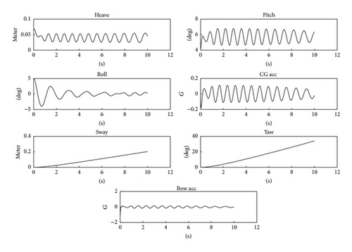
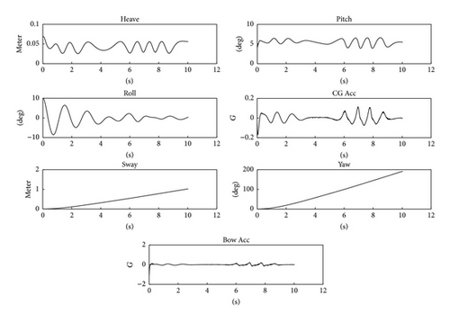
Afterward, an initial roll equal to 5 degrees is examined. Initial conditions are the same as in the previous case except for the roll angle. It is observed that the roll angle is damped after 8 seconds and again increased. This leads to irregular behavior of heave and pitch in regular wave condition. Yaw and sway of planing hull are also increased by time. These results can be analyzed by the fact that damping force acts on the roll motion and decreases it. However, due to the asymmetric fluid flow in roll motion, some yaw moment and sway force are generated, and regular wave force causes a severe increase in sway and yaw motions. Consequently, roll motion will also be intensified. Due to these behaviors, irregular heave and pitch motions exist.
When roll angle is increased to 10 degrees, a similar behavior can be seen too. However, magnitudes of planing motions are different. It is observed that roll motion is relatively damped at 3 until 5 seconds. At the same time, heave and pitch motions remain constant, and, consequently, vertical accelerations due to water impact phenomenon are omitted. However, encounter wave acts on the hull and leads to a new roll angle. In the meantime, yaw and sway motions increase at a relatively constant rate.
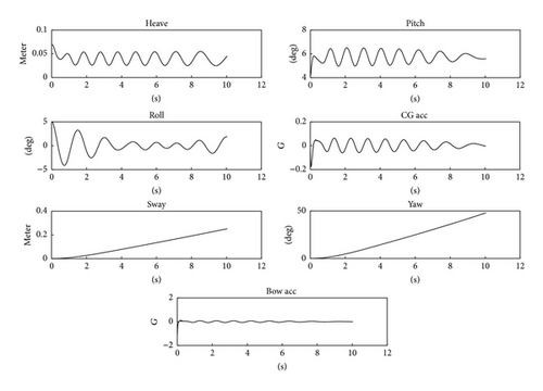
In addition to case 15, case 17 (Table 2) is also considered with the same methodology. Initial roll angle is defined, and it is observed that at zero roll angle, planing hull has a regular behavior. It is clearly seen that no sway and yaw motions are created and that the presented mathematical model works appropriately. As expected, bow acceleration is also larger than the CG acceleration. It is due to this fact that main water entry phenomenon occurs at the fore part of the hull.
At 5 degrees roll angle, after 8 seconds, roll is damped and heave of the hull is increased, and, consequently, pitch motion is relatively damped. However, roll motion is affected by the encounter wave and is thus intensified. Moreover, due to the wave effects and unsteady roll motion, sway and yaw continue by a constant rate. Finally, it must be mentioned that variation of surge velocity is not yet completely modeled, and must be considered in the next version of the developed code.
In the last part of case 17, roll angle of 10 degrees is considered. Similar behavior relative to the third part of case 15 can be observed. In a range of time, roll is damped, and as a result, heave, pitch, and acceleration become constant. Further studies must be performed for understanding these physics.
9. Conclusions
In this paper, various theories of momentum, added mass and 2d + t theories are implemented to develop a mathematical model for simulation of six degrees of freedom motion of a planing craft in regular waves. Therefore, 2d + t theory is developed for asymmetric wedge water entry, and a set of formulas is derived for computation of various forces and moments on planing hulls. Solution of equations of motions is also considered by a well-known numerical method Runge-Kutta-Merson which controls the time step size efficiently.
In the absence of any six degrees computational data or experiments for planing craft motions, it was decided to validate the present model by using Fridsma’s experiment in regular waves for heave and pitch motions. Comparisons indicate that the developed code can model planing motion reasonably accurate. Furthermore, to demonstrate the model capability for six degrees of freedom computations, Fridsma model is considered and effort was made to study the planing hull behavior at the initial roll angles. Three roll angles including 0, 5, and 10 degrees are considered, and the behavior of the planing hull is studied. It is observed that for different wave conditions, similar behavior is observed at similar roll angles. Moreover, due to the roll motion, an intensive sway motion may occur. Irregular heave and pitch motions are also generated due to the asymmetric effect of the roll motion and the encounter wave. These simulations show the reasonable behavior of the developed mathematical model. It must be mentioned that variation of surge velocity is not completely modeled yet and will be considered in the next version of the developed code. Moreover, some experimental studies should be conducted to further develop or modify the presented mathematical model.
Nomenclature
-
- a:
-
- Wave amplitude
-
- aBF:
-
- Buoyancy coefficient
-
- b:
-
- Instantaneous half beam of the section
-
- :
-
- Time derivative of b
-
- CD:
-
- Drag coefficient
-
- Cpu:
-
- Splash-up coefficient
-
- de:
-
- Effective depth of penetration
-
- d:
-
- Depth of penetration
-
- fCD:
-
- Viscous lift force associated with the cross flow drag
-
- fM:
-
- Hydrodynamic lift force associated with the change of fluid momentum per unit length
-
- :
-
- fM associated with port side
-
- :
-
- fM associated with starboard side
-
- Fx, Fy, Fz:
-
- Force in x, y, and z directions
-
- h:
-
- Submergence of a section
-
- IGxx, IGyy, IGzz:
-
- Moment of inertia in xx, yy, and zz directions
-
- k:
-
- Wave number
-
- ka:
-
- Added mass coefficient
-
- Kr, Pr, Rr:
-
- Hydrostatic moment in xx, yy, and zz directions
-
- Kw, Pw, Rw:
-
- Hydrodynamic moment in xx, yy, and zz directions
-
- Kf, Pf, Rf:
-
- Wave moment in xx, yy, and zz directions
-
- lw:
-
- Wetted length
-
- m:
-
- Mass
-
- ma:
-
- Added mass
-
- :
-
- Added mass associated with port side
-
- :
-
- Added mass associated with starboard side
-
- :
-
- Time derivative of added mass
-
- Mx, My, Mz:
-
- Moment in xx, yy, and zz directions.
-
- t:
-
- Time
-
- U:
-
- Velocity component parallel to the keel
-
- V:
-
- Normal velocity
-
- :
-
- Time derivative of normal velocity
-
- wz:
-
- Vertical component of the wave orbital velocity at the surface
-
- :
-
- Time derivative of wz
-
- xCG,, yCG, zCG:
-
- Position of center of gravity (COG) of the hull in x, y and z directions
-
- , , :
-
- Velocity at COG in x, y, and z directions
-
- , , :
-
- Acceleration at COG in x, y, and z directions
-
- Xr, Yr, Zr:
-
- Hydrostatic force in x, y, and z directions
-
- Xw, Yw, Zw:
-
- Hydrodynamic force in x, y, and z directions
-
- Xf, Yf, Zf:
-
- Wave force in x, y, and z directions
-
- (ζ, ξ):
-
- Coordinate system on the hull
-
- ρ:
-
- Water density
-
- τ:
-
- Trim angle
-
- β:
-
- Deadrise angle
-
- η:
-
- Wave height
-
- μ:
-
- Angle between ship heading and wave direction
-
- v:
-
- Wave slope
-
- ωe:
-
- Encounter frequency
-
- ε:
-
- Phase angle
-
- ψ:
-
- Roll angle
-
- :
-
- Angular velocity of roll motion
-
- :
-
- Acceleration of roll motion
-
- θ:
-
- Pitch angle
-
- :
-
- Angular velocity of pitch motion
-
- :
-
- Acceleration of pitch motion
-
- φ:
-
- Yaw angle
-
- :
-
- Angular velocity of yaw motion
-
- :
-
- Acceleration of yaw motion.


