Retrieving 3D Wind Field from Phased Array Radar Rapid Scans
Abstract
The previous two-dimensional simple adjoint method for retrieving horizontal wind field from a time sequence of single-Doppler scans of reflectivity and/or radial velocity is further developed into a new method to retrieve both horizontal and vertical winds at high temporal and spatial resolutions. This new method performs two steps. First, the horizontal wind field is retrieved on the conical surface at each tilt (elevation angle) of radar scan. Second, the vertical velocity field is retrieved in a vertical cross-section along the radar beam with the horizontal velocity given from the first step. The method is applied to phased array radar (PAR) rapid scans of the storm winds and reflectivity in a strong microburst event and is shown to be able to retrieve the three-dimensional wind field around a targeted downdraft within the storm that subsequently produced a damaging microburst. The method is computationally very efficient and can be used for real-time applications with PAR rapid scans.
1. Introduction
Updrafts and downdrafts are the essential components of storms. Their strengths often determine the type and evolution stage of storms. Quickly detecting updrafts and downdrafts and estimating their strengths in storm wind fields will make timely and accurate assessments of hazardous weather conditions. It is thus desirable to develop an efficient method to retrieve both the horizontal and vertical winds, including updrafts and downdrafts, in real time from phased array radar (PAR) rapid scans of storms. A key advantage of PAR over Weather Surveillance Radar 1988-Doppler (WSR-88D) is the capability to rapidly and adaptively scan storms. With its agile electronic beam steering, the PAR scan strategy can be optimized on particular weather phenomena with the volume scan time reduced from minutes to seconds (Zrnic et al. [1], Torres et al. [2]). High spatial and temporal resolution volumetric radar data are often necessary to resolve very fine echo structures, their transient developments, and movements inside storms (Heinselman et al. [3]). Previous research also indicates that the retrieval errors can be reduced if the reflectivity and radial-velocity fields are sampled more frequently (Qiu and Xu [4], Shapiro et al. [5]).
Since Doppler radar observations are limited mainly to reflectivity and radial-component velocity (along the radar beam) and there is no direct measurement of the remaining two wind components perpendicular to the radar beam, a two-dimensional simple adjoint (2D-SA) method was developed by Qiu and Xu [6] to retrieve the horizontal wind field from radar scans at low-elevation angles. In this 2D-SA method, a simplified reflectivity advection equation which is used to predict the reflectivity and the time-mean velocity that advects the reflectivity field in this equation is estimated by minimizing the difference between the radar observed and predicted reflectivity fields. The method was then refined and successfully tested with many real radar observations (Xu et al. [7, 8]). Built on the above success, a three-dimensional simple adjoint (3D-SA) method was developed by Xu et al. [9]. By using the full momentum equations and the mass continuity equation as weak constraints, this 3D-SA method can retrieve the three-dimensional wind field and the perturbation potential temperature field, similarly to the four-dimensional adjoint (4DA) method with a complete system of dynamic and thermodynamic equations (Sun and Crook [10]). Computationally, this 3D-SA method is more efficient than the 4DA method but still too expensive to apply to real-time observations from PAR rapid scans. As the control variable dimension in the 3D-SA method is much larger than that in the 2D-SA method, the 3D-SA method is not only computationally more expensive but also less flexible to adapt to incomplete data coverage than the 2D-SA method. In view of the above limitations, the 3D-SA method has not been applied to PAR data. Instead, the 2D-SA method can be further developed into a two-step SA method in which the vertical velocity is retrieved in a selected vertical cross-section along the radar beam in the second step after the horizontal velocity is retrieved in the first step on the conical surface at each tilt of PAR scans in a targeted domain. The basic idea and formulations of this two-step SA method are described in the next section. The method is applied to PAR observations for a selected case in Section 3. The benefits of rapid scans and the usefulness of mesoscale background wind field are examined in Section 4. Conclusions follow in Section 5.
2. Description of the Method
2.1. Basic Idea
To reduce the computational cost, the horizontal and vertical winds will be retrieved separately in two steps. In the first step, the 2D-SA method is used to retrieve the horizontal winds on each conical surface of the radar scans in a targeted domain of convective scale, while the mesoscale background horizontal wind field is provided by the existing radar wind analysis system that was developed based on the statistic interpolation for real-time applications with the operational WSR-88D radars (Xu et al. [11]). The vertical velocity is then retrieved in the second step in the along-beam vertical cross-section that cuts through the concerned feature at the center of the targeted domain. Since the horizontal winds are retrieved in the first step and their related terms are known in the forecast equation in the second step, the control variable dimension is reduced in the second step.
2.2. Horizontal Wind Retrieval in the First Step
2.3. Vertical Wind Retrieval in the Second Step
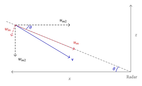
3. Application to PAR Data
3.1. PAR Observations and Mesoscale Background Wind Field
The multimission PAR, located at the National Weather Radar Testbed (NWRT), Norman, Oklahoma, is a research radar using a converted U.S. Navy SPY-1A phased array antenna. This PAR has essentially the same wavelength (9.4 cm in S band) and range resolution (250 m) as the WSR-88D radars, and it can mimic WSR-88D volume coverage patterns (VCPs) and collect data at similar pulse repetition intervals. The most significant difference between the PAR and the WSR-88D is that the phased array antenna forms each beam electronically by controlling the phases of transmit-receive elements and thus can scan storms rapidly and adaptively. With its rapid scan capability, the PAR captured the rapid evolution of a severe storm produced microburst at the 20 km radial range to the south-southwest during the early evening of July 10, 2006. The PAR applied a beam multiplexing scanning strategy to volume coverage pattern 12 (VCP12) for a 90° sector scan, so each volume scan contained up to 53 tilts (with the elevation angles from 0.51° to 41°) and is completed in just 34 seconds. Since the retrieval domain is small and not very close to the PAR, only 14 tilts (from 0.51° to 19.5°) are intercepted by the retrieval domain and will be used for the retrievals in this paper. The storm and its produced microburst were fully sampled in time and space by the PAR. In particular, the PAR detected a reflectivity core aloft between 19 : 40 : 21 and 19 : 42 : 20 UTC at about 6 km above ground level. This reflectivity core produced a strong downdraft maximized around 19 : 49 : 07 UTC as shown in Figure 2, and this downdraft generated a strong outflow near the surface sampled by the PAR from 19 : 50 : 15 to 19 : 58 : 07 UTC (Heinselman et al. [3]).
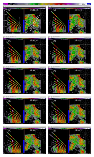
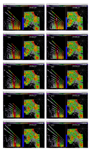
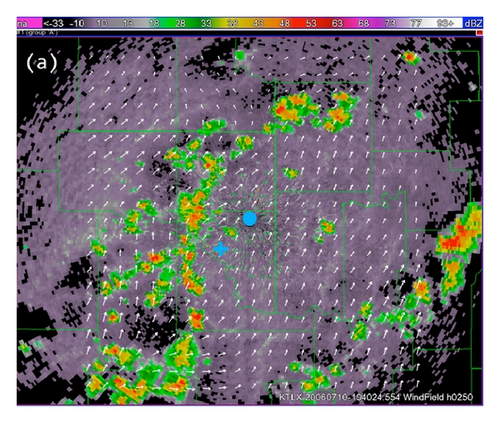
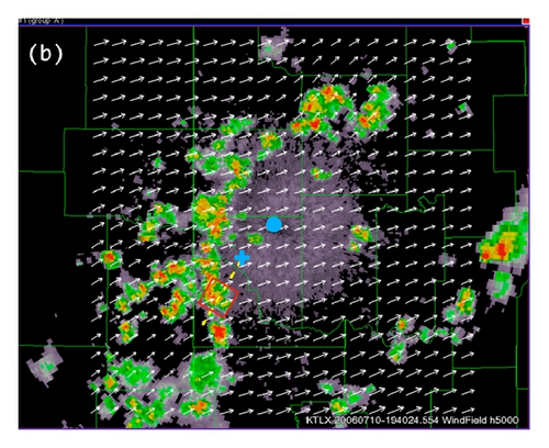
As mentioned in Section 2.1, the radar wind analysis system (Xu et al. [11]) is used to produce the mesoscale background horizontal wind field. For the storm case shown in Figure 2, this system is applied to radial-velocity data from the operational KTLX radar at the Oklahoma City Twin Lakes in combination with surface wind data from the Oklahoma Mesonet. The analysis domain is centered at the KTLX radar site. The domain size is 160 × 160 × 8 km3 covered by a 81 × 81 × 32 grid, the horizontal resolution is Δx = Δy = 2 km, and the vertical resolution is Δz = 0.25 km. The background wind fields produced at 19 : 40 : 24 UTC are shown by white arrows in Figure 3(a) at z = 0.25 km and Figure 3(b) at z = 5 km (above the KTLX radar site) superimposed on the KTLX reflectivity images at 0.5° and 3.3° tilts, respectively. The small red square in panel (b) of Figure 3 marks the nested domain used by the two-step SA method. As shown in Figure 3(a), the low-level background flow is divergent (or convergent) on the mesoscale to the southwest (or northeast) on the upstream (or downstream) side of the nested domain. This mesoscale divergence (or convergence) is consistent with the weakened (or enhanced) upper-level reflectivity in Figure 3(b), relative to the lower-level reflectivity in Figure 3(a), in the area to the southwest (or northeast) on the upstream (or downstream) side of the nested domain, because the weakened (or enhanced) upper-level reflectivity indicates that its associated convective-cell cluster had started to decay (or grow) and thus produced lower-level divergence (or convergence). In the nested domain, the background wind field is smooth and nearly constant at each vertical level. Clearly, the mesoscale background wind field cannot resolve the small-scale flow structures associated with the convective cell in the nested domain. As we can see from Figure 3, the lower-level and upper-level reflectivity fields have about the same intensity in the nested domain, and this suggests that the convective cell in the nested domain was fully developed around 19 : 40 : 00 UTC. The small-scale flow structure associated the downdraft produced by the convective cell in the nested domain can be retrieved by the two-step SA method as shown in the next two subsections.
3.2. Experiment Design
The nested horizontal domain on the conical surface of each tilt of PAR scan is centered at the radial range of r = 20 km from the PAR (marked by the blue + sign in Figure 3) with the x-axis along the PAR beam at the 210.7° azimuth (as shown by the yellow dashed line in Figure 3). The domain size is 16 × 16 km2 (as shown by the white dashed boundary lines in the right panel of Figure 2(a)) covered by a 65 × 65 grid with a horizontal resolution of Δx = Δy = 250 m. The x-axis of the vertical cross section is thus also along the 210.7° azimuth and centered at r = 20 km from the PAR, while the vertical domain size is 15 × 7.5 km2 (as shown by the white dashed boundary lines in the left panel of Figure 2(a)) covered by a 61 × 31 grid with Δx = Δz = 250 m. The total of 26 volume scans (one volume every Δτ = 34~64 s) for the time period from 19 : 40 : 00 to 20 : 00 : 00 UTC are used by the two-step SA method to retrieve the wind fields over 24 time windows. Each time window contains N = 3 consecutive volume scans, so τ = (N − 1)Δτ ≈ 1 min. The time step is Δt = 2.5 s for the forward integrations of (3a), (3b), and (3c) and (13a), (13b), and (13c) and the backward integrations of (9a), (9b), and (9c) and (18a), (18b), and (18c).
3.3. Results Obtained in the First Step
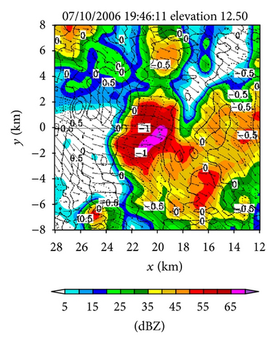
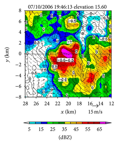
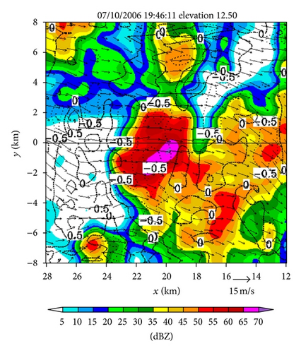
Figures 4(a)–4(f) show the retrieved (um, vm) fields in the nested domain on the conical surfaces of six tilts (selected from the total 14 tilts from 0.51° to 19.5°) from the PAR 90° sector scans over the time period of 19 : 45 : 43~19 : 46 : 13 UTC. Note that the x-coordinate is along the 210.7° azimuth (as shown by the dashed yellow line in Figure 3(b)). Thus, as shown in Figure 4, the prevailing winds in the nested domain were southwesterly on the conical surface of θ = 0.51° (around z ≈ 0.2 km) but veered with height and gradually changed to westerly on the conical surface of θ = 15.6° (around z ≈ 8 km). This feature is consistent with the vertical variation of the background winds in Figure 3. In addition to this feature, the retrieved quasi-horizontal wind field exhibits strong storm-scale variations inside and around the main reflectivity core area (with reflectivity >40 dBZ) on each conical surface. The detailed storm-scale flow structures and associated horizontal divergence/convergence patterns are examined below.
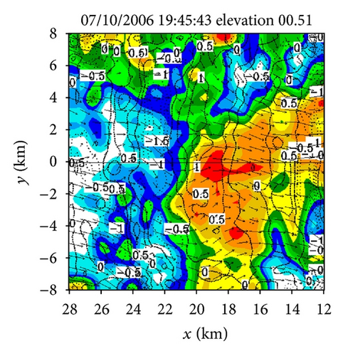
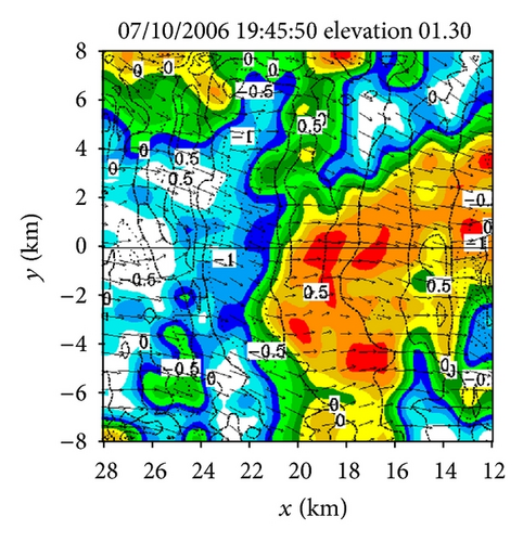
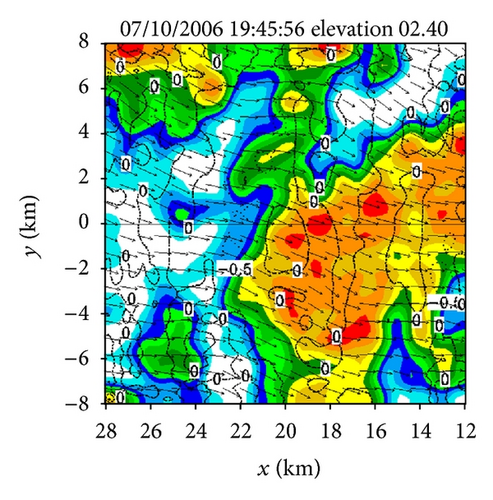
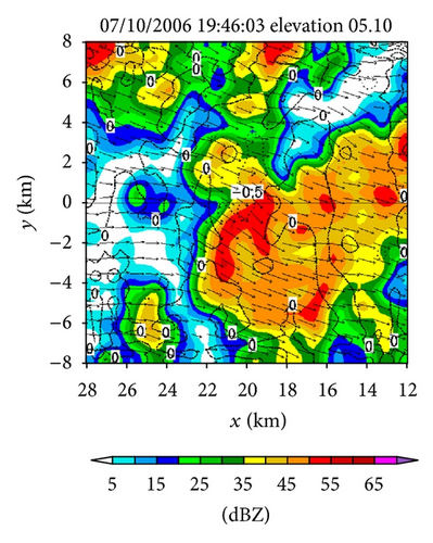
From Figures 4(a) and 4(b) we can see that before the lower-level inflow (from the left boundary of the domain) reached the reflectivity core area, the flow was not only deflected rightward but also became strongly convergent (shown by the dashed negative contours of horizontal divergence) in a narrow elongated area to the left of the reflectivity core area. Inside the reflectivity core area, the lower-level flow was strongly divergent, as shown by the solid positive contours of the horizontal divergence in the reflectivity core area in Figure 4(a). This strong lower-level divergence was caused by and tied up with a strong downdraft aloft, while this strong downdraft is not only revealed by the downward movement of the reflectivity core as exhibited by the time series of RHI display in Figures 2(a)–2(t) but also well retrieved in the second step (as shown later in Figure 6(c)).
On the other hand, as we can see from Figures 4(e) and 4(f), the upper flow was divergent in a narrow elongated area to the left of the reflectivity core and became convergent inside the reflectivity core. From Figures 4(c) and 4(d), we can see that the middle-level flow was weakly convergent or divergent, and the convergence-divergence pattern for the middle-level flow is intermediate between the two nearly opposite patterns at the lower and upper levels. Thus, at least qualitatively, the retrieved quasi-horizontal wind fields in the first step captured the storm scale convergence-divergence patterns associated with the strong downdraft generated by the storm.
Figures 5(a) and 5(b) show the reflectivity source fields (see the Sm term on the right-hand side of the reflectivity advection equation in (3a)) obtained as by-products of the retrievals in Figures 4(a) and 4(e) on the conical surfaces of θ = 0.51° and 12.5°, respectively. As shown in Figure 5(a), the retrieved reflectivity source field on the 0.51° tilt is characterized by small-scale fluctuations around zero, and the RMS amplitude of these small-scale fluctuations is smaller by several times than the RMS amplitudes of the local time derivative and advection terms (not shown) in the reflectivity advection equation. Note that the vertical advection term is implicitly absorbed into the source term Sm on the right-hand side of (3a), and this vertical advection term includes the effect of hydrometeors’ downward terminal velocity, whereas the vertical gradient of reflectivity was small and more or less positive in the lower level (around z ≈ 0.2 km on the 0.51° tilt as shown by the RHI display in Figure 2(d)). Thus, the contribution of the vertical advection to Sm is weakly positive in the lower level. This positive contribution could offset the negative contribution to Sm produced by precipitation evaporation (since the evaporation could be also weak as implied by the small vertical gradient of reflectivity around z ≈ 0.2 km). This may explain the smallness of the retrieved Sm in Figure 5(a), although the source term Sm also absorbs residual errors of the reflectivity advection equation in (3a) especially those caused by the imperfect reflectivity observations and imperfect velocity retrievals.
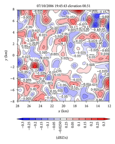
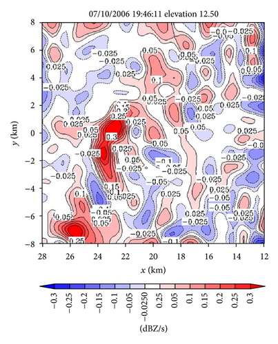
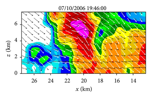
In the upper level (around z ≈ 8 km on the 12.5° tilt), as shown in Figure 5(b), the retrieved source term Sm is maximized in the narrow curved area along and inside the left boundary of the reflectivity core (as seen by overlapping Figure 5(b) onto Figure 4(e)). In this curved upper-level area, the upward vertical velocity of air largely cancelled the downward terminal velocity for hydrometeors (as seen later from the retrieved vertical velocities in Figure 6(c)), and the vertical gradient of reflectivity was very small (on the 12.5° tilt as shown by the RHI display in Figure 2(d)). The vertical advection of reflectivity was thus very small, so only the condensation caused by the upward air motion may explain why the source term Sm is maximized in the curved upper-level area as we have seen from Figure 5(b).
As another by-product, the horizontal turbulent diffusivity coefficient kh is also retrieved, and the retrieved value varies slightly with the scan elevation and time window. The mean value of the retrieved kh is 274 m2 s−1 with a standard deviation of 30 m2 s−1. These retrieved values of kh are in the same range as those obtained or used in the previous studies of the 2D-SA method (see the second paragraph in Section 2 of Xu et al. [8] and reference cited there).
3.4. Results Obtained in the Second Step
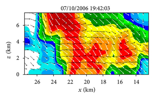
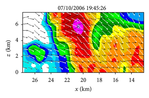
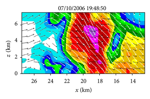
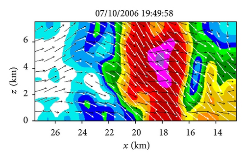
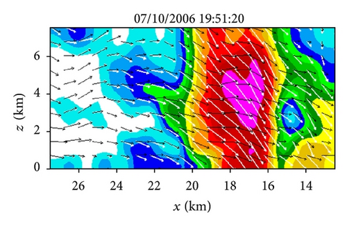
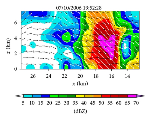
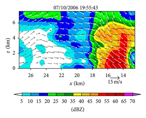
Figures 6(a)–6(h) show the time series of the retrieved fields for air motions (plotted by black arrows) in the vertical cross-section along the x-coordinate in the nested domain superimposed on the PAR-observed reflectivity fields from 19 : 42 : 03 to 19 : 55 : 43 UTC on July 10, 2006. As we can see from Figures 6(a)–6(c), the air motions were upward within the reflectivity core, especially in the upper levels, and their produced condensation may largely explain the rapid intensification of the reflectivity core. However, as the reflectivity core moved down to the middle levels and finally reached the ground, the upward air motions inside the reflectivity core became weak and even changed to slightly downward motions (as shown in Figures 6(d)–6(h) and thus ceased to produce condensation during the later times. This may largely explain why the reflectivity core ceased to grow and even became slightly weak as it fell into and below the middle levels during the later time period from 19 : 48 : 50 to 19 : 55 : 43 UTC, as shown in Figures 6(d)–6(h). Furthermore, as shown by the white arrows in Figures 6(a)–6(h), the vector velocities of hydrometeors were overwhelmingly downward especially inside the reflectivity core, and their vertical-component velocities are around the value (≈6.3 m s−1) as estimated by the downward movements of the reflectivity core from the time series of the RHI displays in Figure 2.
Note that the vertical advection term is explicitly considered in (13a), so the source term Sm2 on the right-hand side of (13a) should be related primarily to the production/reduction of hydrometeors caused by condensation/evaporation, although the source term Sm2 also absorbs the residual errors caused in (13a) by the imperfect reflectivity observations and imperfect velocity retrievals. Figure 7 shows the Sm2 field produced in the vertical cross-section as a by-product of the retrieval in Figure 6(c). By overlapping Figure 7 onto Figure 6(c), it is easy to see that the red-colored positive core of Sm2 > 0.2 dBZ s−1 in the middle levels is inside the main updraft (where the upward air motions are maximized) within the reflectivity core, so this middle-level positive core of Sm2 can be largely explained by the condensation and associated production of hydrometeors in the main updraft. Similarly, the upper-level negative core of Sm2 < −0.2 dBZ s−1 between 20 km > x > 18 km along the top boundary of Figure 7 can be largely explained by the evaporation and associated reduction of hydrometeors due to the downward advection of hydrometeors into a relatively dry area (with reduced reflectivity) as shown in Figure 6(c). However, all other relatively weak positive and negative cores in Figure 7 do not seem to be physically meaningful and they may merely represent the residual errors caused in (13a) by the imperfect reflectivity observations and imperfect velocity retrievals.

As another by-product, the vertical turbulent diffusivity coefficient kz is also retrieved. The retrieved values for the different time windows are almost the same. The mean value of the retrieved kz is 201 m2 s−1, and the standard deviation is merely 0.25 m2 s−1. Note that all values of kz are retrieved for the same along-beam vertical domain over a short time period, and the bulk effect of the vertical turbulent diffusion could remain nearly the same over this short time period. This may partially explain why the standard deviation is small. The retrieved values of kz are roughly within the same range as those of kh retrieved in the first step.
4. Benefits of PAR Rapid Scans and Usefulness of Mesoscale Background Wind Field
4.1. Benefits of PAR Rapid Scans
As mentioned in the introduction, the retrieval errors can be reduced if the reflectivity and radial velocity fields are scanned more rapidly than the operational WSR-88D radar scans (Qiu and Xu [4], Shapiro et al. [5]). A similar benefit is expected for the two-step SA method developed in this paper and applied to PAR rapid scans. To demonstrate this, an additional experiment is performed in this subsection with the input PAR sector scan data used every 5 min instead of every 30 s, so the temporal resolution of the input observations is reduced by 10 times and becomes about the same as that of the operational WSR-88D radar scans. The parameter settings in this experiment are the same as those described for the experiment in Section 3.2 except that Δτ is increased to 5 min and thus τ = (N − 1)Δτ is increased to 10 min (since N = 3 is unchanged). This experiment will be called Expt-5 min, while the experiment performed in Section 3 will be used as the benchmark.
Figures 8(a) and 8(b) show the (um, vm) fields retrieved from the first step of Expt-5 min on the conical surfaces of θ = 0.51° and 12.50°, respectively, and they are the 10 min time-mean wind fields centered at the same times (19 : 45 : 43 and 19 : 46 : 11 UTC) as the 1 min time-mean wind fields in Figures 4(a) and 4(e), respectively. As we can see, the retrieved wind field in Figure 8(a) (or Figure 8(b)) is weaker and slightly smoother than that in Figure 4(a) (or Figure 4(e)) although their gross patterns are similar. The reduced intensity and spatial variability for the retrievals in Figures 8(a) and 8(b) can be attributed largely to the reduced temporal resolution of the input observations and its caused increase of the time window (from τ = 1 to 10 min) for the time-mean wind retrieval. Figures 9(a) and 9(b) show the difference fields obtained by subtracting the (um, vm) fields in Figures 4(a) and 4(e) from those in Figures 8(a) and 8(b), respectively. The spatially averaged RMS values of the two difference fields are 3.08 and 4.25 m s−1, respectively. These RMS differences can represent roughly the RMS errors caused by coarsening the temporal resolution of the input observations from Δτ = 0.5 to 5 min, because the retrievals from Expt-5 m are significantly less accurate than those from the benchmark experiment, as evaluated indirectly below.

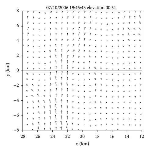
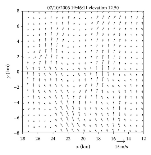
The 1 min time-mean wind fields retrieved in the benchmark experiment are less smeared in time and therefore expected to be more accurate than the 10 min time-mean wind fields retrieved in Expt-5 min. However, since the true fields are not known, it is difficult to directly evaluate whether and how much the retrieval accuracy is improved by rapid scans. To overcome this difficulty, we resort to the square root of the first (or second) cost-function term Jη (or Jvr) in (1) that measures the RMS difference of the predicted η (or retrieved vrm) to the observed reflectivity ηob (or radial-velocity vrob) averaged over the retrieval time window τ. Note that J is nondimensional and the weight Wη in Jη (or Wvr in Jvr) is inversely proportional to τ as shown in (22a), so the aforementioned RMS difference is measured by (or ) in the same way for different τ. Thus, the relative accuracies of retrievals obtained with different τ can be evaluated indirectly by comparing the initial values of Rη (or Rvr) and subsequent reductions achieved through the iterative descending of J for different τ. To facilitate the comparison, the terms R ≡ J1/2, Rη, and Rvr computed from the first step of the benchmark experiment (or Expt-5 min) are denoted by R-30 s, Rη-30 s, and Rvr-30 s (or R-5 min, Rη-5 min and Rvr-5 min), respectively. These terms are plotted in Figure 10 as functions of iteration number n by the dashed curves for the retrieval in Figure 8(a) versus those plotted by the solid curves for the retrieval in Figure 4(a). By comparing the red (or blue) solid curve with the red (or blue) dashed curve in Figure 10, we can see that the ratio of Rη-5 min (or Rvr-5 min) to Rη-30 s (or Rvr-30 s) is as large as 7.3 (or 6.9) at n = 0 and increases to 9.3 (or 10.9) at n = 100. Similar large ratios are seen (not shown) from the retrieval in Figure 8(b) versus that in Figure 4(e). These large ratios imply that the first-step retrievals from Expt-5 m are significantly less accurate than those from the benchmark experiment.
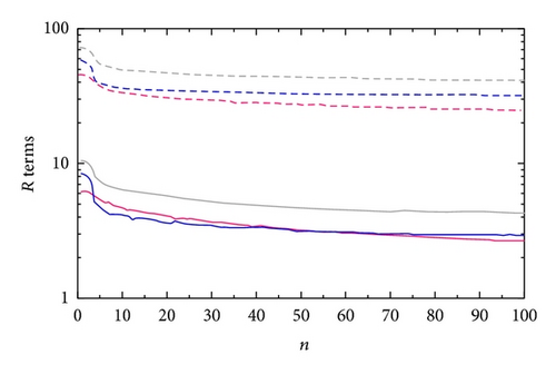
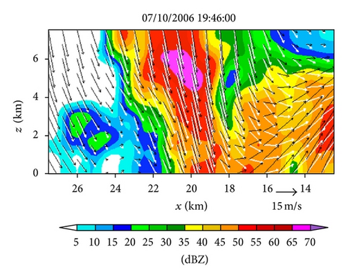
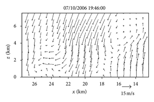
Figure 11(a) shows the field for air motions (plotted by black arrows) retrieved from the second step of Expt-5 min around the same time as that (19 : 46 : 00 UTC) in Figure 6(c). As shown, the retrieved vertical-velocity field in Figure 11(a) has much stronger variations than that in Figure 6(c). In particular, the hydrometeors’ downward vertical velocities (shown by the white arrows) inside the reflectivity core in Figure 11(a) are much larger than the value of 6.3 m s−1, estimated from the downward movements of the reflectivity core in Figure 2 (see figure’s caption for the estimated value), whereas the downward vertical velocities of hydrometeors inside the reflectivity core in Figure 6(c) are very close to and around the estimated value of 6.3 m s−1. Thus, the retrieval in Figure 11(a) is significantly less accurate than that from the benchmark experiment in Figure 6(c). Figure 11(b) shows the difference field obtained by subtracting the field in Figure 11(a) from that in Figure 6(c). The spatially averaged RMS value of this difference field is 13.31 m s−1. This large RMS difference is caused mostly by the RMS error of the retrieval in Figure 11(a), and the latter is caused both directly by the reduced temporal resolution of the input observations in the second step and indirectly by the reduced accuracies in the horizontal velocities retrieved in the first step and used in the second step. This large increase of retrieval error is also reflected by the large ratio of Rη-5 min/Rη-30 s (≈15), where Rη-5 min (or Rη-30 s) is the square root of the first cost-function term in (12) computed from Expt-5 min (or benchmark experiment). Thus, the PAR rapid scans can improve not only the horizontal-wind retrieval in the first step but also the vertical-velocity retrieval in the second step, and the improvement is more significant in the second step.
4.2. Usefulness of Mesoscale Background Wind Field
For the particular case considered in this paper, the targeted retrieval domain is small and the mesoscale background velocity (ub, vb) is smooth and nearly constant on each tilt within this small domain. Because of this, the retrieved (um, vm) fields in Figure 4 change insignificantly when the background wind field is not used, while the retrieved fields in Figure 4 change even less due to the fact that the background vertical velocity is zero. These properties are verified by another additional experiment performed with no background wind, that is, (ub, vb) = 0 and thus (Δum, Δvm) = (um, vm). This experiment will be called Expt-NB.
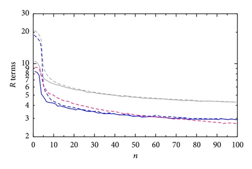
The terms R, Rη, and Rvr computed from the first step of Expt-NB are denoted by R-30 s NB, Rη-30 s NB, and Rvr-30 s NB, respectively. These terms are plotted in Figure 12 as functions of the iteration number n by the dashed curves versus those plotted by the solid curves for the retrieval in Figure 4(a). By comparing the red (or blue) solid curve with the red (or blue) dashed curve in Figure 12, we can see that the ratio of Rη-30 s NB (or Rvr-30 s NB) to Rη-30 s (or Rvr-30 s) is 1.5 (or 2.2) at n = 0, decreases rapidly to 1.09 (or 1.03) at n = 10, and then gradually approaches 1.000 (or 1.000) as n further increases toward 100. These ratios are large initially, and this is because the unknown control variables (Δum, Δvm) = (um, vm) are zero initially in Expt-NB and thus have larger errors than those in the benchmark experiment where (Δum, Δvm) = (um, vm)−(ub, vb) are zero initially. Thus, using the mesoscale background velocity field can reduce the initial errors of the control variables (Δum, Δvm). The mesoscale background velocity should be more useful than just reducing the initial errors of the control variables for the two-step SA method if the retrieval domain is not too small (as that in this paper) to resolve some mesoscale variations from the background field. This speculation needs to be verified in future applications of the two-step SA method.
5. Conclusions
In this paper, the simple adjoint method (Qiu and Xu [6], Xu et al. [7, 8, 17]) is further developed into a two-step method to retrieve high-resolution horizontal and vertical wind fields from the PAR rapid scans of convective storm cells in a targeted domain. The first step retrieves the horizontal vector wind field on the conical surface of radar scan at each elevation angle, and the second step retrieves the vertical velocity in an along-beam vertical cross-section. As the horizontal winds can be retrieved in parallel on different elevations in the first step and only the vertical velocity needs to be retrieved in the second step, this two-step method is computationally efficient. In particular, on a workstation with Intel(R) Xeon(R) CPU X7550 (2.00 GHz), the computer time for the first step is about 20 s (with the retrievals performed in parallel for different tilts) and the computer time for the second step is merely 10 s. Thus, the method can be applied very efficiently to real-time PAR rapid scans. The performance and expected capability of the method are demonstrated by a real-data example in Section 3 where the method is applied to PAR rapid 90° sector scans of a severe storm that produced a strong downdraft and subsequent damaging microburst during the early evening of July 10, 2006.
The above severe storm was scanned not only by the PAR but also by the operational KTLX radar (about every 5 minutes per volume) and the terminal Doppler weather radar (also about every 5 minutes per volume). These two operational radars, however, are all located in the same northeast quadrant as the PAR relative to the storm, so real dual-Doppler observations are not available for quantitative verifications of the single-Doppler retrievals obtained in this paper. Nevertheless, the method used in the first step is a refinement of the previous 2D-SA method, and the previous method has been tested for many real cases with the retrieved wind fields well verified by dual-Doppler analyses (Xu et al. [7, 8]). Thus, the method in the first step should remain at least as reliable as the previous 2D-SA method, and this speculation is supported by the detailed analysis of the retrievals obtained in the first step (see Section 3.3). The method developed for the second step is new. This new method performs well with the PAR rapid scans as suggested by the detailed analysis of the retrievals obtained in the second step (see Section 3.4), but the performance deteriorates significantly when the temporal resolution of the input observations is coarsened from 0.5 to 5 min to mimic the operational WSR-88D radar scans (see Section 4.1).
Note that the 2D-SA can be also formulated in the polar coordinates centered at the radar (instead of the local Cartesian coordinates as shown in Figure 2(a)) with the retrieval performed in a targeted sector area on each tilt of radar scan essentially in the same way as that in Xu et al. [18] and Xu and Qiu [17]. After these sector-area retrievals are performed in parallel for different tilts in the first step, the second step can be performed efficiently in parallel for different along-beam vertical cross-sections. In this way, the method can retrieve high-resolution three-dimensional wind fields in real time from PAR rapid scans over various adaptively-nested sector areas threatened by damaging winds generated by severe storms. This real-time capability will be developed and tested in future studies.
Acknowledgments
The authors are thankful to Dr. Alan Shapiro and anonymous reviewers for their comments and suggestions that improved the representation of the results and to GuangYu Wang for his help in editing Figure 4. The research was supported by ONR Grant N000141010778 to the University of Oklahoma (OU), NOAA-OU Cooperative Agreement NA17RJ1227, and Tianjin Municipal Meteorological Bureau Grant 201316.


