A Chaos-Based Secure Direct-Sequence/Spread-Spectrum Communication System
Abstract
This paper proposes a chaos-based secure direct-sequence/spread-spectrum (DS/SS) communication system which is based on a novel combination of the conventional DS/SS and chaos techniques. In the proposed system, bit duration is varied according to a chaotic behavior but is always equal to a multiple of the fixed chip duration in the communication process. Data bits with variable duration are spectrum-spread by multiplying directly with a pseudonoise (PN) sequence and then modulated onto a sinusoidal carrier by means of binary phase-shift keying (BPSK). To recover exactly the data bits, the receiver needs an identical regeneration of not only the PN sequence but also the chaotic behavior, and hence data security is improved significantly. Structure and operation of the proposed system are analyzed in detail. Theoretical evaluation of bit-error rate (BER) performance in presence of additive white Gaussian noise (AWGN) is provided. Parameter choice for different cases of simulation is also considered. Simulation and theoretical results are shown to verify the reliability and feasibility of the proposed system. Security of the proposed system is also discussed.
1. Introduction
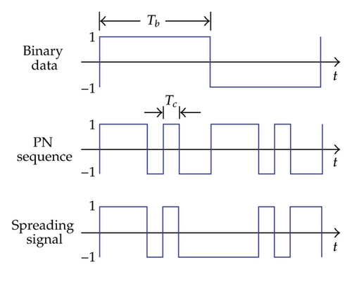
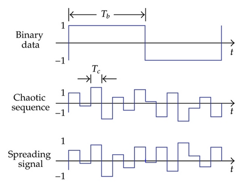
Studying the possibilities of using chaotic behavior [1, 2] to improve features of communication systems has received significant attention in the last several years [3–5]. Many chaos-based communication systems were proposed [6, 7] and most of them exploited chaotic behavior to convey information. Communication systems based on combination of direct-sequence/spread-spectrum (DS/SS) and chaos techniques were presented in [8–10]. It is well known that DS/SS is considered as a main technique of spread-spectrum digital communications [11, 12]. The main difference between the conventional and chaos-based DS/SS systems is the use of spreading sequence. Instead of using the pseudonoise (PN) sequence [13, 14] as in the conventional system, the spread- and despread-spectrum processes in the chaos-based system are carried out by multiplying directly the binary data with a chaotic sequence generated by a chaotic map [1, 2, 15, 16]. Time domain signals shown in Figures 1(a) and 1(b) illustrate the difference in the conventional and chaos-based DS/SS systems, where Tb and Tc are fixed bit and chip durations, respectively.
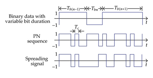
In this paper, we propose a chaos-based secure DS/SS communication system which is the combination of the DS/SS and chaos techniques. Bit duration is varied according to the behavior of chaotic map but always equal to a multiple of the fixed chip duration. Variation in bit duration makes the difference between our proposed system and the conventional ones. The data bits with variable duration are spread in the frequency domain by multiplying directly with the PN sequence and then modulated onto a sinusoidal carrier by means of the binary phase-shift keying (BPSK) [17, 18]. The spread-spectrum process of our proposed chaos-based DS/SS system is illustrated by time domain signals as in Figure 1(c), where Tbn is the variable duration of the nth bit. Since the proposed system operates based on the DS/SS using PN sequence, it inherits all advantages such as interference rejection, antijamming, fading reduction, multiaccess potential, and low probability of interception from the conventional DS/SS system [11, 12]. In addition, data security is improved significantly since the despread-spectrum and data recovery process needs an identical regeneration of both the PN sequence and chaotic behavior.
In the remainder of the paper, the structure and operation of the proposed communication system is presented in Section 2. Theoretical evaluation of BER performance in presence of additive white Gaussian noise (AWGN) is provided in Section 3. Section 4 presents analysis of parameters choice for the system, based on that specific parameters for different cases of simulation system are chosen with proper values. Simulation results are then shown to verify the theoretical ones. Discussions on security features are presented in Section 5. Finally, the conclusion with some final remarks is given in Section 6.
2. Structure and Operation of Chaos-Based Secure DS/SS Communication System
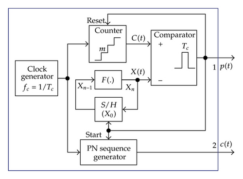
In this section, we present a detailed analysis of the structure and operation of the chaos-based DS/SS communication system proposed. Basically, the proposed system is built around a variable-position pulse and PN sequence (VPP-PNS) generator. Block diagrams of the proposed system and that of the VPP-PNS generator are illustrated in Figures 2(a) and 2(b), respectively.

2.1. VPP-PNS Generator
2.2. Transmitter
2.3. Receiver
The VPP-PNS generators in the transmitter and receiver are designed to work as digital modules which can be implemented on the programmable devices such as the field programmable gate array (FPGA), digital signal processing (DSP), and microprocessor (MP). In practice, this design can be guaranteed such that there is nearly no parameters mismatch between the VPP-PNS generators. It means that the variable-position pulse train and PN sequence regenerated in the receiver are identical to those in the transmitter. Therefore, we can apply the available synchronization methods of the conventional DS/SS system [11, 12, 18] for the proposed system. Here, for simplicity, the operation of the receiver assumes that the synchronization in the sinusoidal carrier, variable-position pulse train, and PN sequence is established and maintained.
3. Theoretical Evaluation of BER Performance
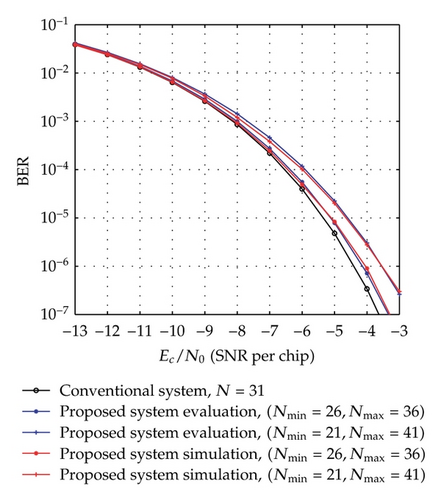
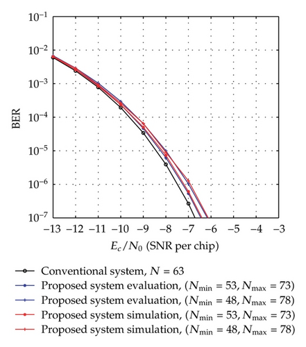
The evaluation BER performances according to (22) for different cases of [Nmin, Nmax] with the same average spreading factor as well as their comparison with the performance of the equivalent conventional system are shown in Figure 3. With the above assumption of the uniformly distributed chaotic values, the average spreading factor and average bit rate are determined by Nav = (Nmin + Nmax)/2 and BRav = 2/((Nmin + Nmax)Tc), respectively. In Figure 3(a), the performances of the proposed system for the cases of [Nmin = 26, Nmax = 36] and [Nmin = 21, Nmax = 41], are compared to each other and to that of the conventional system [21] which has a fixed spreading factor, N = Nav = 31. It can be seen that the proposed system with the case of [Nmin = 26, Nmax = 36] performs slightly worse than the conventional system with N = 31 and better than the [Nmin = 21, Nmax = 41] case. Similarly, we can observe from Figure 3(b) that the performance of [Nmin = 53, Nmax = 73] case is between those of the conventional system with N = 63 and the case of [Nmin = 48, Nmax = 78]. It is clear that the performance of the proposed system with [Nmin, Nmax] is poorer than that of conventional system with N = Nav. In addition, the difference between the performance of the proposed system and that of conventional one tends to diminish as the average value (Nmin + Nmax)/2 gets closer to N = Nav.
4. Parameter Choice and Simulation Results
This section presents the analysis of parameter choice for the proposed system. Based on the analysis, the specific parameters for different cases of the simulation system are chosen with proper values. The simulation results are then shown in order to verify all the theoretical analyses and results obtained.
4.1. Parameter Choice
4.2. Simulation Results
Numerical simulations for different cases of the proposed system with the specific parameters are carried out in Simulink. The values of the predetermined parameters of the simulation system are given as follows: Tc = 1 μs; four cases of [Nmin, Nmax] = [26, 36], [21, 41], [53, 73], and [48,78]; three conventional chaotic maps simulated in turn are Tent map, Logistic map, and Bernoulli map [1, 2, 15, 16], whose output values vary chaotically in [xmin = 0, xmax = 1]. Based on the choice analysis above, the values of the specifications and chosen parameters of the simulation system corresponding to the different cases of [Nmin, Nmax] are determined and shown as in Table 1.
| Predetermined parameters | Specifications of system | Chosen parameters | |||||||
|---|---|---|---|---|---|---|---|---|---|
| Chaotic map | |||||||||
| Tc | [Nmin, Nmax] | f(·) : xn = f(xn − 1) [xmin = 0, xmax = 1] |
BW | BRav | BER | m | F(·) : Xn = F(Xn−1) [Xmin = d, Xmax = d + 1] |
d | X0 |
| [26, 36] |
|
32.25 Kbps | Blue lines in Figure 2(a) | 0.1/μs | Xn = 2|0.5−|0.5 − (Xn−1 − d)|+d| | 2.65 | 2.7 | ||
| 1 μs | [21, 41] |
|
1 MHz | 0.05/μs | Xn = 4(Xn−1 − d)(1 − (Xn−1 − d)) + d | 1.075 | 1.1 | ||
|
|
15.87 Kbps | Blue lines in Figure 2(b) |
|
Xn = ((2(Xn−1 − d)) mod 1) + d |
|
|
||
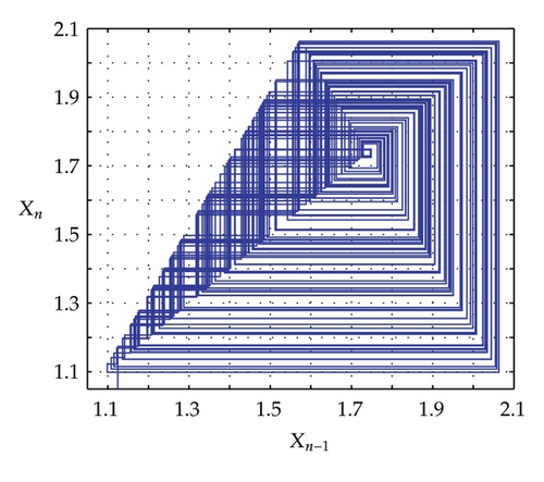
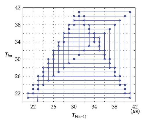
Time domain signals obtained from the simulation system using Tent map for the case of [Nmin = 21, Nmax = 41] within duration from the starting time 0 to 1000 μs are presented in Figure 4. When the synchronization state of system is established and maintained, the signals of the VPP-PNS generators in the transmitter and receiver are identical and shown as in Figures 4(a)–4(d). The baseband signals in the transmitter and receiver are given in Figures 4(e)-4(f) and Figures 4(g)–4(i), respectively. The chaotic behavior the nonlinear converter F(·) is seen by the attractor diagram in Figure 5(a). It is clear that this is the attractor of Tent map after being shifted with a positive value, d = 1.075. The variation in bit duration according to the chaotic behavior is given in the diagram as in Figure 5(b), where each point expresses the relation between the duration of previous bit and that of the present one. It can be seen that the bit duration varies in the range of [Tbmin = 21 μs, Tbmax = 41 μs].


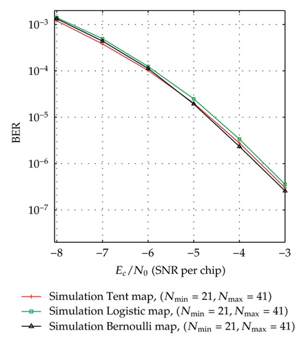
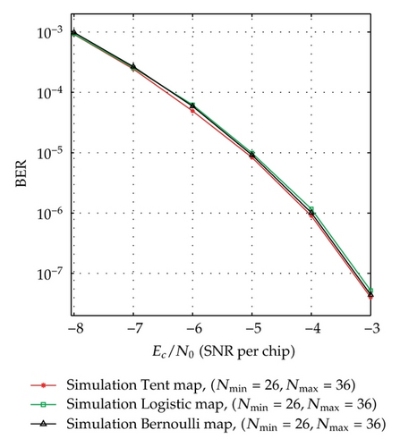
BER performance of the simulation system using Tent map for the cases of [Nmin = 26, Nmax = 36], [Nmin = 21, Nmax = 41], [Nmin = 53, Nmax = 73], [Nmin = 48, Nmax = 78] is presented in Figure 3 to compare with the corresponding theoretical performance. In order to investigate the performance of the proposed system with different chaotic maps, the simulation systems using Tent, Logistic, and Bernoulli maps for the cases of [Nmin = 21, Nmax = 41] and [Nmin = 26, Nmax = 36] are carried out and the result is as shown in Figure 6. Here, the simulation BERs are calculated as the number of error bits divided by the total number of 108 bits transmitted and the channel noise is AWGN. It can be seen from Figure 3, for each case, that the simulation and corresponding evaluation curves are nearly the same. Also, Figure 6 shows that there is a slight difference in the simulation curves of the different chaotic maps. These prove that the theoretical analysis and the result are reasonable and the proposed communication system is totally feasible.
5. Discussion on Security
It is clear that the conventional DS/SS-BPSK system, an intruder can break the security and recover successfully the original data if he detects correctly the PN sequence and the integration period which is equal to bit rate. Since the bit duration is the same and fixed in the observation process, it is not difficult for the intruder to detect exactly bit rate. Several detection methods of bit rate have been presented in [22, 23]. It means that the security of the conventional system mainly depends on the complication of PN sequence.
Since our proposed system is combined by the DS/SS technique using PN sequence and chaotic modulation, the data transmitted by using the proposed system must be more secure from eavesdroppers than that in case of using individual methods. In other words, the security has been compromised by burying chaotic modulation in the conventional DS/SS technique. With the presence of the conventional DS/SS technique in the proposed system, the transmitted signal has properties like random noise and occupies a wide bandwidth with a very low power spectral density on the transmission channel. It means that the proposed system inherits the security advantages from the conventional method such as the anti jamming capability and low probability of detection and interception [24, 25]. In addition, with the variation of bit duration according to the chaotic behavior, the capability to protect data against unauthorized accesses is improved significantly.
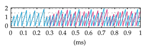
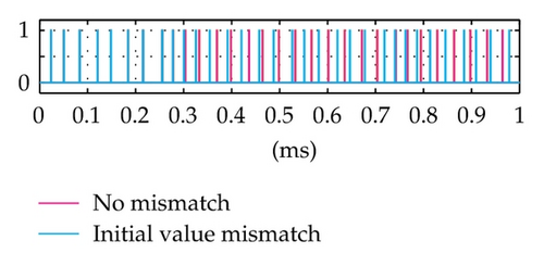
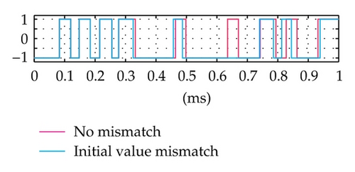
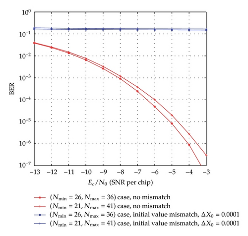
More specifically, the data security of the proposed system is dependent on not only on the complication of PN sequence but also on the variation of the integration period (i.e., the bit duration) according to the chaotic behavior. It is seen that the generation of the chaotic behavior is quite simple for the transmitter and the authorized receiver which has full information on the structure, the value of parameters and functions. In fact, the exact regeneration of chaotic behavior in the proposed system is very difficult for intruders trying to detect them in the context that the chaotic system is covered by the PN sequence generator. Due to the sensitive dependence of the chaotic behavior on the initial value, a very slight error in its detection leads to exponentially increasing errors in the regeneration. In such case, the detection of the variation of bit duration is completely incorrect and the receiver operates in the desynchronization state. As a result, BER will be very high and thus the unauthorized access is failed. These are proved by simulation results in Figures 7 and 8, where the time domain signals and BER performances of the receiver in the case of initial value mismatch (with a very small difference, ΔX0 = 0.0001) are shown and compared with those in the case of no mismatch. We can observe that after about 0.2 ms from the starting time, the mismatch signals become totally different from the corresponding no-mismatch signals. The BER performance with the mismatch is much worse than that of the cases with no-mismatch. Particularly, although the ratio Ec/N0 increases gradually, the mismatches in BER are nearly unvaried and approximately equal to 1.6 10−1. It is noticed that the set of values of m, X0, and F(·) is considered as a secret key. It is hard for the intruder to recover correctly the data without having full information on the structure of the system, the PN sequence, and this secret key. Furthermore, the generation of the chaotic values can easily be made as complicated as is desired. For example, instead of the one-dimension maps, we can use multidimension chaotic ones. Also, several chaotic maps may be combined to increase the number of parameters involved. The initial value can be changed for different communication sessions. All these will improve significantly the security of the proposed method.

Most of the attack methods are proposed in order to break the chaotic communication systems [26–29] operated based on exploiting properties such as waveform, spectrum, and attractor of the chaotic signal which masks the information and is transmitted directly on the channel. In the proposed system, the signal transmitted on the channel is totally the same as that of the conventional system and without any trace of the chaotic behavior; thus, the existing attack methods are inapplicable to the proposed system. It means that no chance for the intruder to be able to detect the variation of bit duration from the physical signal on the channel. It is also clear that the conventional detection methods of bit rate mentioned above cannot detect in detail this variation. They may detect the variation range and average value of bit duration, but this is not sufficient for a successful access.
6. Conclusion
This study has presented a chaos-based secure DS/SS communication system which is based on a novel combination of the conventional DS/SS and chaos techniques. The structure, operation, and BER performance of the proposed system are described and investigated by means of the theoretical analysis and numerical simulation. The simulation result agrees with the theoretical analysis. The discussion shows the potential of security improvement. It can be seen from the obtained results, that is, (1) the proposed system inherits all the advantages from the conventional system such as the interference rejection, antijamming, fading reduction, multiaccess capability, and low probability of interception due to its operation also based on the DS/SS using PN sequence and BPSK technique; (2) with the variation of bit duration according to the chaotic behavior in the communication process, the proposed system not only still maintains an approximately good performance but also achieves significant improvement on the data security in comparison with the equivalent conventional system. All these features make the proposed system feasible and robust for the security required and DS/SS-based digital communication system.
Acknowledgment
This work is supported by the Vietnam’s National Foundation for Science and Technology Development (NAFOSTED) under Grant no. 102.02-2012.34.


