An Improved Nonlinear Five-Point Model for Photovoltaic Modules
Abstract
This paper presents an improved nonlinear five-point model capable of analytically describing the electrical behaviors of a photovoltaic module for each generic operating condition of temperature and solar irradiance. The models used to replicate the electrical behaviors of operating PV modules are usually based on some simplified assumptions which provide convenient mathematical model which can be used in conventional simulation tools. Unfortunately, these assumptions cause some inaccuracies, and hence unrealistic economic returns are predicted. As an alternative, we used the advantages of a nonlinear analytical five-point model to take into account the nonideal diode effects and nonlinear effects generally ignored, which PV modules operation depends on. To verify the capability of our method to fit PV panel characteristics, the procedure was tested on three different panels. Results were compared with the data issued by manufacturers and with the results obtained using the five-parameter model proposed by other authors.
1. Introduction
Several methods have been suggested for predicting the behavior of operating photovoltaic (PV) modules. The basis of most of them is the equivalent electrical circuit represented in the simplest way by a current source in parallel with one or many diodes describing the P-N junction. An improved version includes parasitic series and shunt resistances. In general, multidiode representations modeling P-N junctions of PV devices offer accurate results at the expense of long computational time. For simplicity, the single-diode model is used in this paper. This model offers a good compromise between simplicity and accuracy [1, 2] and has been used by numerous authors. It involves the determination of five parameters, namely, photocurrent (Iph), diode saturation current (I0), ideality factor (a), parasitic series, and shunt resistances (Rs) and (Rsh), respectively.
Due to the transcendental nature of the I-V relationship for PV modules, significant computation efforts are required to obtain all the related device parameters. One can distinguish the analytical methods which make it possible to calculate independently each parameter according to given limiting conditions [3, 4] and those based on simultaneous determination of a part or all of the set of parameters using algebraic calculations [5]. Iterative calculations have been carried out recently using artificial intelligence (AI) techniques such as fuzzy logic (FL) [6] and artificial neural network (ANN) [7, 8].
- (i)
All the connected cells are identical and work under the same conditions of illumination and temperature.
- (ii)
The short-circuit current is equivalent to photocurrent and hence proportional to the level of solar irradiation.
- (iii)
The variation of open-circuit voltage with irradiance is known to follow a logarithmic function based on an ideal diode equation, and the effect of temperature is due to an exponential increase in the diode saturation current with an increase in temperature.
- (iv)
Voltage drops in the conductors connecting the cells are negligible.
The main purpose of this paper is to present an improved methodology for characterizing PV systems. Based on the classical five-point model, amendatory terms are introduced to take into account the effects of nonideal diode parameters and nonlinearity effects that PV module behaviors depend on. Furthermore, series resistance is evaluated using nonlinear fitting of experimental data. Results are compared to experimental data provided by PV modules manufacturers and an existing model.
2. Theory and Analysis
2.1. PV Module Model
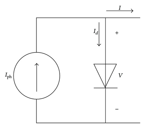
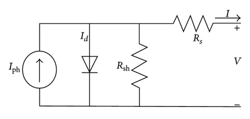
2.2. Nonlinear Five-Point Model
The five-point model is an analytical method to extract related device parameters from values of key operational quantities measured from well-defined points of I-V characteristic, namely, the open circuit voltage Voc, the short-circuit current Isc, the voltage at maximum power point Vmp, the current at maximum power point Imp, the slope at open-circuit point , and the slope at short-circuit point [14–17]. Using this method, the additional terms that account for nonlinear effects are not directly associated with expressions of related device parameters, but they are allocated to the key operational quantities abovementioned. This approach makes it possible to adequately tame the concept of nonlinearity in well-known point of I-V characteristic in order to make device parameters depend on easily used pieces of information derived from operational PV module.
2.2.1. Calculating Key Operational Quantities
2.2.2. Calculating Related Device Parameters
Beyond the core losses related to the selective absorption of light and recombination, there are significant energy degradations due to parasitic resistances. Resistive effects in solar cells reduce efficiency by dissipating power in the resistance. Making their evaluation based on operating conditions is extremely important for studying the electrical behaviors of photovoltaic devices.
2.2.3. Calculation of the Constants
3. Results and Discussions
The capabilities of the nonlinear five-point model to predict the electrical response of PV devices is validated by measured experimental data of selected PV modules. Three PV modules of different technologies are used for investigation; these include monocrystalline, multicrystalline and thin-film types, namely, Shell SM55, Shell S75, and Shell ST40, respectively. The experimental data were extracted from manufacturer’s data sheet [27]. The specifications of these modules are summarized in Table 1.
| Parameter | Monocrystalline (Si) SM55 | Multicrystalline (Si) S75 | Thin-film (CIS) ST40 |
|---|---|---|---|
| Isc (A) | 3.45 | 4.7 | 2.68 |
| Voc (V) | 21.7 | 21.6 | 23.3 |
| Imp (A) | 3.15 | 4.26 | 2.41 |
| Vmp (V) | 17.4 | 17.6 | 16.6 |
| (mA/°C) | 1.4 | 2 | 0.35 |
| (mV/°C) | −76 | −76 | −100 |
| Ns | 36 | 36 | 42 |
By applying the nonlinear five-point model described in the previous subsection, the computed results of selected PV modules are obtained. The procedure was executed for various irradiance and temperature levels. To evaluate the accuracy of the proposed model, the results obtained are compared to the five-parameter model described in [28].
The constants α, β, and γ can be calculated following the constant estimation procedures given above. The results are shown in Table 2.
| Constant | α | β | γ |
|---|---|---|---|
| Monocrystalline SM55 | 0.984 | 0.058 | 1.064 |
| Multicrystalline S75 | 0.996 | 0.052 | 1.155 |
| Thin-film ST40 | 0.998 | 0.087 | 1.343 |
In Figures 3 and 4 the I-V characteristic curves evaluated using the proposed model are compared to the experimental data issued by manufacturer. The I-V curves of the five-parameter model are not shown for brevity. It can be seen that Figures 2 and 3 show a good agreement between the I-V curves obtained by proposed model and the provided experimental data for all types of modules in various operating conditions analyzed. In particular, the proposed model is very accurate at low irradiance levels. In turn, some little inaccuracies still occur for voltages greater than the maximum power voltage when subjected to temperature variation.
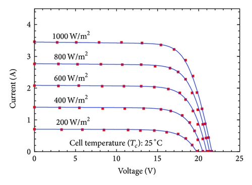
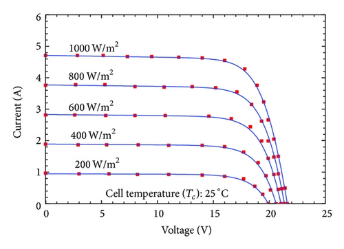
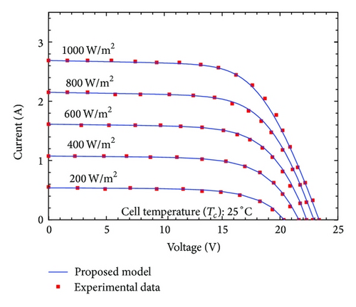
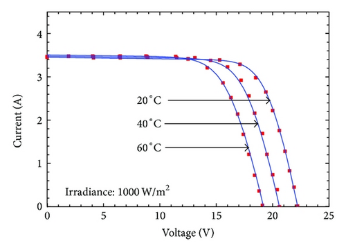
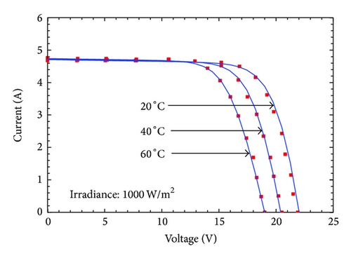
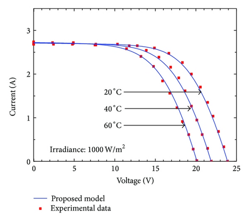
Table 3 lists the values of the related device parameters computed using the proposed and the five-parameter models for various levels of irradiance. It can be noticed, using the five-parameter model, that the constant values of the parameters a, I0, and Rs are obtained when subjected to irradiance variation. This is foreseeable, since the model assumes these parameters to be invariant regardless of irradiance variations. However, the proposed model formulates irradiance dependence for all parameters. Logically, the five-point model can be considered more accurate because the shunt resistance decreases and the series resistance increases with increasing irradiance as stipulated in [29, 30]; the diode ideality factor decreases with increasing irradiance as described in [30, 31].
| Parameter | Monocrystalline SM55 | Multicrystalline S75 | Thin-film ST40 | |||
|---|---|---|---|---|---|---|
| Proposed model | Five-parameter model | Proposed model | Five-parameter model | Proposed model | Five-parameter model | |
| 1000 W/m² | ||||||
| Iph (A) | 3.453 | 3.457 | 4.715 | 4.715 | 2.702 | 2.694 |
| I0 (A) | 9.721E − 8 | 9.906E − 7 | 9.193E − 8 | 2.430E − 7 | 3.463E − 7 | 4.174E − 6 |
| a | 1.338 | 1.183 | 1.311 | 1.388 | 1.361 | 1.75 |
| Rs (Ω) | 0.3 | 0.3625 | 0.2 | 0.1281 | 1.3 | 0.7457 |
| Rsh (Ω) | 350 | 186.5 | 179 | 127.4 | 250 | 140.8 |
| 800 W/m² | ||||||
| Iph (A) | 2.771 | 2.765 | 3.774 | 3.772 | 2.157 | 2.155 |
| I0 (A) | 5.398E − 7 | 9.906E − 7 | 3.961E − 7 | 2.430E − 7 | 2.994E − 6 | 4.174E − 6 |
| a | 1.486 | 1.183 | 1.432 | 1.388 | 1.571 | 1.75 |
| Rs (Ω) | 0.2371 | 0.3625 | 0.1283 | 0.1281 | 1.02 | 0.7457 |
| Rsh (Ω) | 436 | 233.1 | 223.6 | 159.2 | 312.5 | 175.9 |
| 600 W/m² | ||||||
| Iph (A) | 2.087 | 2.074 | 2.832 | 2.829 | 1.616 | 1.617 |
| I0 (A) | 1.624 E − 6 | 9.906E − 7 | 9.402E − 7 | 2.430E − 7 | 13.64E − 6 | 4.174E − 6 |
| a | 1.606 | 1.183 | 1.519 | 1.388 | 1.771 | 1.75 |
| Rs (Ω) | 0.1762 | 0.3625 | 0.117 | 0.1281 | 0.7465 | 0.7457 |
| Rsh (Ω) | 578.7 | 310.8 | 297.8 | 212.3 | 416.7 | 234.6 |
| 400 W/m² | ||||||
| Iph (A) | 1.4 | 1.383 | 1.89 | 1.886 | 1.076 | 1.075 |
| I0 (A) | 3.134E − 6 | 9.906E − 7 | 1.386E − 6 | 2.43E − 7 | 37.685E − 6 | 4.174E − 6 |
| a | 1.698 | 1.183 | 1.512 | 1.388 | 1.95 | 1.75 |
| Rs (Ω) | 0.1155 | 0.3625 | 0.07654 | 0.1281 | 0.4813 | 0.7457 |
| Rsh (Ω) | 862.5 | 466.1 | 446.1 | 318.5 | 625 | 351.9 |
| 200 W/m² | ||||||
| Iph (A) | 0.707 | 0.6913 | 0.9473 | 0.9429 | 0.5377 | 0.5388 |
| I0 (A) | 4.071 E − 6 | 9.906E − 7 | 1.219E − 6 | 2.430E − 7 | 60.709E − 6 | 4.174E − 6 |
| a | 1.763 | 1.183 | 1.582 | 1.388 | 2.085 | 1.75 |
| Rs (Ω) | 0.05624 | 0.3625 | 0.03706 | 0.1281 | 0.2278 | 0.7457 |
| Rsh (Ω) | 1706 | 932.3 | 890 | 636.9 | 1250 | 703.8 |
The computed parameters using the proposed and the five-parameter models for temperature variation are shown in Table 4. Once again, the constant values of the parameters a, Rs, and Rsh are obtained when temperature variation is considered. These are undoubtedly sources of inaccuracies. In turn, the proposed model is consistent with open literature; the diode ideality factor decreases with increasing temperature as issued in [32–34], and the series resistance Rs decreases with increasing temperature which agrees with the work in [35], although its variation rate is more important.
| Parameter | Monocrystalline SM55 | Multicrystalline S75 | Thin-film ST40 | |||
|---|---|---|---|---|---|---|
| Proposed model | Five-parameter model | Proposed model | Five-parameter model | Proposed model | Five-parameter model | |
| 60°C | ||||||
| Iph (A) | 3.502 | 3.507 | 4.744 | 4.73 | 2.712 | 2.706 |
| I0 (A) | 103.914E − 9 | 6.512E − 7 | 110.675E − 9 | 9.058E − 6 | 4.381E − 6 | 108.657E − 6 |
| a | 1.067 | 1.183 | 1.042 | 1.388 | 1.064 | 1.614 |
| Rs (Ω) | 0.2625 | 0.3625 | 0.1747 | 0.1281 | 1.114 | 0.7457 |
| Rsh (Ω) | 350 | 186.5 | 179 | 127.4 | 250 | 140.8 |
| 40°C | ||||||
| Iph (A) | 3.474 | 3.478 | 4.728 | 4.721 | 2.706 | 2.699 |
| I0 (A) | 100.294E − 9 | 6.649E − 8 | 100.308E − 9 | 1.259E − 6 | 3.868E − 7 | 18.365E − 6 |
| a | 1.211 | 1.183 | 1.185 | 1.388 | 1.221 | 1.614 |
| Rs (Ω) | 0.2828 | 0.3625 | 0.1884 | 0.1281 | 1.214 | 0.7457 |
| Rsh (Ω) | 350 | 186.5 | 179 | 127.4 | 250 | 140.8 |
| 20°C | ||||||
| Iph (A) | 3.446 | 3449 | 4.711 | 4.712 | 2.7 | 2.692 |
| I0 (A) | 96.036E − 9 | 5.037E − 9 | 89.039E − 9 | 1.355E − 7 | 3.324E − 7 | 2.467E − 6 |
| a | 1.385 | 1.183 | 1.357 | 1.388 | 1.413 | 1.614 |
| Rs (Ω) | 0.3061 | 0.3625 | 0.2042 | 0.1281 | 1.331 | 0.7457 |
| Rsh (Ω) | 350 | 186.5 | 179 | 127.4 | 250 | 140.8 |
These related device parameters are strongly influenced by the irradiance and temperature. However, computed parameters using the five-parameter model present an obsolete dependence to the variation of environmental conditions. It is obvious that the use of constant parameters determined under STC must bring deviations in replicating the observed behavior of PV module in other operating conditions [28, 29]. Logically, values of related device parameters computed using the five-point model can be considered to be appropriately calculated. Its formulation is based on the PV module operation with the particularity to point out important effects of nonlinearities that environmental variations of parameters depend on. Furthermore, values of these parameters are realistic and in close agreement with results published elsewhere as it has been noticed previously.
For the thin-film type PV module, particularly large values of ideality factor are obtained in low irradiance due to decreasing series resistance. Theoretical approaches predict diode ideality factors in a range 1 < a < 2 dependent on the energy of the recombination center and the respective capture cross sections for electrons and holes. The explanation of a > 2 obtained when G = 200 W/m² is not possible by considering recombination via a single recombination center [36]. However, certain process like the tunneling enhanced recombination applied to thin-film technologies predicts ideality factor that may exceed 2 [36, 37]. The proposed model is based on the operation of PV module with absence of simplification and may lump one or multiple steps recombination process via a series of trap states distributed in space and energy that can result in such large ideality factor.
To provide a clear picture of the precision of the proposed model, the errors using the proposed and five-parameter models are computed. The absolute error is defined as the absolute difference between the experimental and computed current values of the I-V curves for a given voltage point. These calculations are carried out for various irradiance and temperature levels as shown in Figures 5 and 6, respectively.
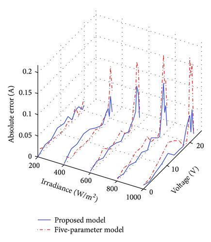
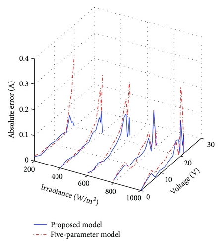
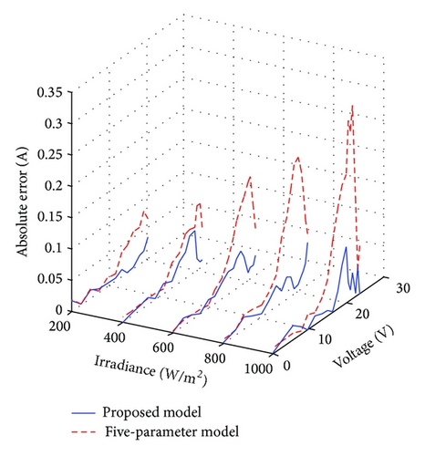
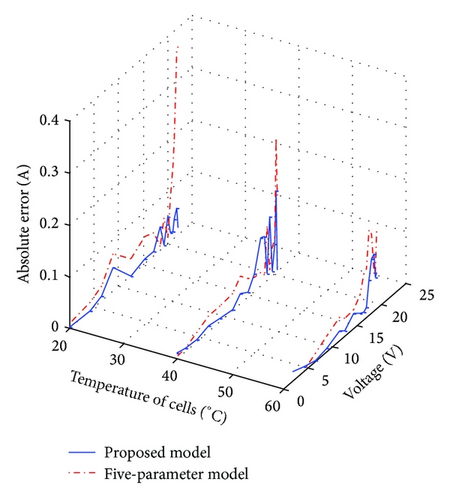
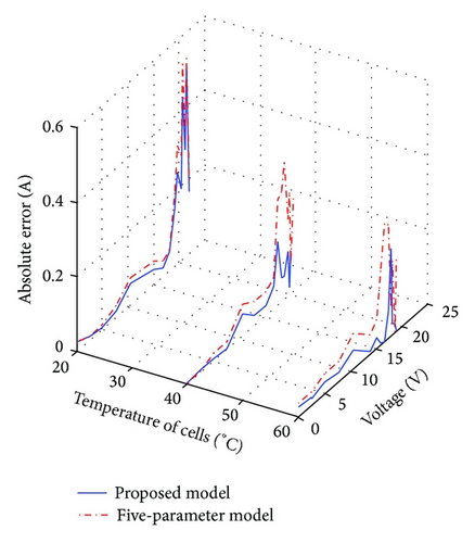
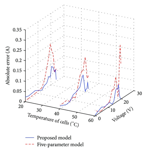
The proposed model globally shows fewer errors than the five-parameter model for various environmental conditions analyzed. This is expected because values of many related device parameters computed using the five-parameter model do not vary with variation of environmental conditions as shown in Tables 3 and 4. However, for proposed model, values of parameters vary with irradiance and temperature. This means that the proposed model taking into account the nonlinear effects leads to appropriate computed parameters.
In most cases, exceptionally high errors occur near the vicinity of MPP. This is ascribable to the fact that the value of the series resistance plays a dominant role in determining the curvature of the I-V curve [34]. For the five-parameter model, constant value of Rs when irradiance and temperature vary results to inaccurate I-V curves in this region. On the other hand, in addition to the nonlinear effects, the determination of Rs using the proposed model is based on complete fitting of experimental data. Thus, the series resistance is adequately computed, and hence the error of the nonlinear five-point model is reduced.
4. Conclusion
In this paper, modeling of electrical response of PV modules using an analytical nonlinear five-point model is described. Unlike the previous models suggested by other researchers, the proposed model computes the PV module parameters at any irradiance and temperature point, using only the datasheet information for a PV module. The accuracy of the proposed model is evaluated using experimental data from the manufacturers of three PV modules of different types. Its performance is compared to a popular five-parameter model. The observed superior accuracy of the proposed model to describe these PV modules behaviors suggests that this proposed model might also represent an even better phenomenological description of the electrical mechanisms prevalent in these particular devices and the nonlinear effects that they depend on. In addition, research on analysis and replication of operation of these specific devices in terms of the proposed model is currently being carried out, but the interest and scope of the proposed nonlinear five-point model is noteworthy. Beyond its simplicity of implementation, the proposed model adequately describes the evolution of these specific devices physical phenomena when subjected to temperature and irradiance variations, and hence it is envisaged that the proposed model can be a valuable design tool for PV system during the production as well as during the use.
Symbols
-
- a:
-
- Ideality factor
-
- CIS:
-
- Copper indium selenide material
-
- G:
-
- Irradiance
-
- I:
-
- Current
-
- MPP:
-
- Maximum power point
-
- R:
-
- Resistance
-
- STC:
-
- Standard test conditions
-
- V:
-
- Voltage
-
- I0:
-
- Saturation current
-
- Iph:
-
- Photocurrent
-
- Si:
-
- Silicon material
-
- VT:
-
- Thermal voltage
-
- Ns:
-
- Number of cells in series
-
- Voc:
-
- Open-circuit voltage
-
- Isc:
-
- Short-circuit current
Subscript
-
- ref:
-
- Reference conditions
-
- mpp:
-
- Maximum power point
-
- oc:
-
- Open-circuit
-
- s:
-
- Series
-
- sc:
-
- Short-circuit
-
- sh:
-
- Shunt.
Greek Letters
-
- μ:
-
- Temperature coefficient
-
- α:
-
- Constant
-
- β:
-
- Constant
-
- γ:
-
- Constant.
Conflict of Interests
There is no competing interests in the validity of this paper due to the choice of the Shell SM55 and Shell SP5 modules.
Acknowledgments
The authors are grateful to Dr. Obounou, Dr. Akana, and Miss Enoh for their efforts in the realization of this work.


