Influence of Hall Current and Thermal Radiation on MHD Convective Heat and Mass Transfer in a Rotating Porous Channel with Chemical Reaction
Abstract
A theoretical study is carried out to obtain an analytic solution of heat and mass transfer in a vertical porous channel with rotation and Hall current. A constant suction and injection is applied to the two insulating porous plates. A strong magnetic field is applied in the transverse direction. The entire system rotates with uniform angular velocity Ω about the axis normal to the plates. The governing equations are solved by perturbation technique to obtain the analytical results for velocity, temperature, and concentration fields and shear stresses. The steady and unsteady resultant velocities along with the phase differences for various values of physical parameters are discussed in detail. The effects of rotation, buoyancy force, magnetic field, thermal radiation, and heat generation parameters on resultant velocity, temperature, and concentration fields are analyzed.
1. Introduction
Free convection in channel flow has many important applications in designing ventilating and heating of buildings, cooling of electronic components of a nuclear reactor, bed thermal storage, and heat sink in the turbine blades. Convective flows driven by temperature difference of the bounding walls of channels are important in industrial applications. El-Hakiem [1] studied the unsteady MHD oscillatory flow on free convection radiation through a porous medium with a vertical infinite surface that absorbs the fluid with a constant velocity. Jaiswal and Soundalgekar [2] analyzed the effects of suction with oscillating temperature on a flow past an infinite porous plate. Singh et al. [3] studied the unsteady free convective flow in a porous medium bounded by an infinite vertical porous plate in the presence of rotation. Pal and Shivakumara [4] studied the mixed convection heat transfer from a vertical plate in a porous medium.
Hydromagnetic convection with heat transfer in a rotating medium has important applications in MHD generators and accelerators design, geophysics, and nuclear power reactors. MHD free convection and mass transfer flows in a rotating system have diverse applications. The effects of Hall currents cannot be neglected as the conducting fluid when it is an ionized gas, and applied field strength is strong then the electron cyclotron frequency ω = eB/m (where e, B, and m denote the electron charge, the applied magnetic field, and mass of an electron, resp.) exceeds the collision frequency so that the electron makes cyclotron orbit between the collisions which will divert in a direction perpendicular to the magnetic and electric fields directions. Thus, if an electric field is applied perpendicular to the magnetic field then whole current will not pass along the electric field. This phenomena of flow of the electric current across an electric field with magnetic field is known as Hall effect, and accordingly this current is known as Hall current [5]. Thus, it is essential to analyze the effects of Hall currents in many industrial problems. Gupta [6] has studied the influence of Hall current on steady MHD flow in a viscous fluid. Jana et al. [7] analyzed the hall effect in steady flow past an infinite porous flat plate. Makinde and Mhone [8] studied hydromagnetic oscillatory flow through a channel having porous medium. Zhang and Wang [9] analyzed the effect of magnetic field in a power-law fluid over a vertical stretching sheet. Hameed and Nadeem [10] analyzed unsteady hydromagnetic flow of a non-Newtonian fluid over a porous plate. Makinde et al. [11] examined the effect of magnetic field in a rotating porous medium cylindrical annulus. Sibanda and Makinde [12] analyzed effects of magnetic fields on heat transfer on a rotating disk in a porous medium with Ohmic heating and viscous dissipation. Pop and Watanabe [13] analyzed convective flow of a conducting fluid in the presence of magnetic field and Hall current. Saha et al. [14] studied Hall current effect on MHD natural convection flow from vertical flat plate. Recently, Pal et al. [15] examined the influence of Hall current and chemical reaction on oscillatory mixed convection radiation of a micropolar fluid in a rotating system.
Radiation effects on free convection flow have become very important due to its applications in space technology, processes having high temperature, and design of pertinent equipments. Moreover, heat and mass transfer with thermal radiation on convective flows is very important due its significant role in the surface heat transfer. Recent developments in gas cooled nuclear reactors, nuclear power plants, gas turbines, space vehicles, and hypersonic flights have attracted research in this field. The unsteady convective flow in a moving plate with thermal radiation were examined by Cogley et al. [16] and Mansour [17]. The combined effects of radiation and buoyancy force past a vertical plate were analyzed by Hossain and Takhar [18]. Hossain et al. [19] analyzed the influence of thermal radiation on convective flows over a porous vertical plate. Seddeek [20] explained the importance of thermal radiation and variable viscosity on unsteady forced convection with an align magnetic field. Muthucumaraswamy and Senthil [21] studied the effects of thermal radiation on heat and mass transfer over a moving vertical plate. Pal [22] investigated convective heat and mass transfer in a stagnation-point flow towards a stretching sheet with thermal radiation. Aydin and Kaya [23] justified the effects of thermal radiation on mixed convection flow over a permeable vertical plate with magnetic field. Mohamed [24] studied unsteady MHD flow over a vertical moving porous plate with heat generation and Soret effect. Chauhan and Rastogi [25] analyzed the effects of thermal radiation, porosity, and suction on unsteady convective hydromagnetic vertical rotating channel. Ibrahim and Makinde [26] investigated radiation effect on chemically reaction MHD boundary layer flow of heat and mass transfer past a porous vertical flat plate. Pal and Mondal [27] studied the effects of thermal radiation on MHD Darcy-Forchheimer convective flow past a stretching sheet in a porous medium. Palani and Kim [28] analyzed the effect of thermal radiation on convection flow past a vertical cone with surface heat flux. Recently, Mahmoud and Waheed [29] examined thermal radiation on flow over an infinite flat plate with slip velocity.
The study of heat and mass transfer due to chemical reaction is also very importance because of its occurrence in most of the branches of science and technology. The processes involving mass transfer effects are important in chemical processing equipments which are designed to draw high value products from cheaper raw materials with the involvement of chemical reaction. In many industrial processes, the species undergo some kind of chemical reaction with the ambient fluid which may affect the flow behaviour and the production quality of final products. Aboeldahab and Elbarbary [30] examined heat and mass transfer over a vertical plate in the presence of magnetic field and Hall effect. Abo-Eldahab and El Aziz [31] investigated the Hall current and Joule heating effects on electrically conducting fluid past a semi-infinite plate with strong magnetic field and heat generation/absorption. Kandasamy et al. [32] discussed the effects of chemical reaction and magnetic field on heat and mass transfer over a vertical stretching surface. Muthucumaraswamy and Janakiraman [33] analyzed the effects of mass transfer over a vertical oscillating plate with chemical reaction. Sharma and Singh [34] have analyzed the unsteady MHD free convection flow and heat transfer over a vertical porous plate in the presence of internal heat generation and variable suction. Sudheer Babu and Satya Narayan [35] examined chemical reaction and thermal radiation effects on MHD convective flow in a porous medium in the presence of suction. Makinde and Chinyoka [36] studied the effects of magnetic field on MHD Couette flow of a third-grade fluid with chemical reaction. Recently, Pal and Talukdar [37] investigated the influence of chemical reaction and Joule heating on unsteady convective viscous dissipating fluid over a vertical plate in porous media with thermal radiation and magnetic field.
The objective of the present study is to analyze the effects of Hall current, thermal radiation, and first-order chemical reaction on the oscillatory convective flow and mass transfer with suction injection in a rotating vertical porous channel. The present results are compared with those of Singh and Kumar [38], and a very good agreement is found.
2. Problem Formulation
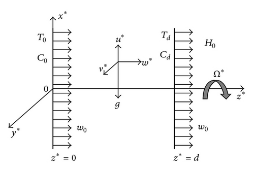
We consider unidirectional oscillatory free convective flow of a viscous incompressible and electrically conducting fluid between two insulating infinite vertical permeable plates separated by a distance d. A constant injection velocity w0 is applied at the stationary plate z* = 0. Also, a constant suction velocity w0 is applied at the plate z* = d, which oscillates in its own plane with a velocity U*(t*) about a nonzero constant mean velocity U0. The channel rotates as a rigid body with angular velocity Ω* about the z*-axis perpendicular to the planes of the plates. A strong transverse magnetic field of uniform strength H0 is applied along the axis of rotation by neglecting induced electric and magnetic fields. The fluid is assumed to be a gray, emitting, and absorbing, but nonscattering medium. The radiative heat flux term can be simplified by using the Rosseland approximation. It is also assumed that the chemically reactive species undergo first-order irreversible chemical reaction.
3. Method of Solution
4. Amplitude and Phase Difference due to Steady and Unsteady Flow
5. Amplitude and Phase Difference of Shear Stresses due to Steady and Unsteady Flow at the Plate
6. Results and Discussion
The system of ordinary differential equations (14) with boundary conditions (15) is solved analytically by employing the perturbation technique. The solutions are obtained for the steady and unsteady velocity fields from (16)–(18), temperature fields from (19)–(21), and concentration fields are given by (22)–(24). The effects of various parameters on the thermal, mass, and hydrodynamic behaviors of buoyancy-induced flow in a rotating vertical channel are studied. The results are presented graphically and in tabular form. Temperature of the heated wall (left wall) at z* = 0 is a function of time as given in the boundary conditions, and the cooled wall at z* = d is maintained at a constant temperature. Further, it is assumed that the temperature difference is small enough so that the density changes of the fluid in the system will be small. When the injection/suction parameter λ is positive, fluid is injected through the hot wall into the channel and sucked out through the cold wall. The numerical results of the amplitude of the shear stresses and the phase difference of the shear stresses at the stationary plate (z* = 0) for the steady and unsteady flow are presented in Table 1. The effect of various physical parameters on flow, heat, concentration fields, skin-friction, Nusselt number, and Sherwood number are presented graphically in Figures 2–16.
| Gr | M | m | λ | Ω | Pr | Singh and Kumar [38] | Present results | ||
|---|---|---|---|---|---|---|---|---|---|
| τ0r | β0 | τ0r | β0 | ||||||
| 5 | 2 | 1 | 0.5 | 10 | 0.71 | 4.5847 | 0.7279 | 4.5847 | 0.7279 |
| 10 | 2 | 1 | 0.5 | 10 | 0.71 | 4.6515 | 0.6815 | 4.6515 | 0.6815 |
| 5 | 4 | 1 | 0.5 | 10 | 0.71 | 5.2797 | 0.6395 | 5.2797 | 0.6395 |
| 5 | 2 | 3 | 0.5 | 10 | 0.71 | 4.4862 | 0.7627 | 4.4862 | 0.7627 |
| 5 | 2 | 1 | 1.0 | 10 | 0.71 | 4.6162 | 0.6229 | 4.6162 | 0.6229 |
| 5 | 2 | 1 | 0.5 | 20 | 0.71 | 6.3323 | 0.7614 | 6.3323 | 0.7614 |
| 5 | 2 | 1 | 0.5 | 40 | 0.71 | 8.8924 | 0.7783 | 8.8924 | 0.7783 |
| 5 | 2 | 1 | 0.5 | 80 | 0.71 | 12.558 | 0.7857 | 12.558 | 0.7857 |
| 5 | 2 | 1 | 0.5 | 10 | 7.0 | 4.5726 | 0.7198 | 4.5726 | 0.7198 |
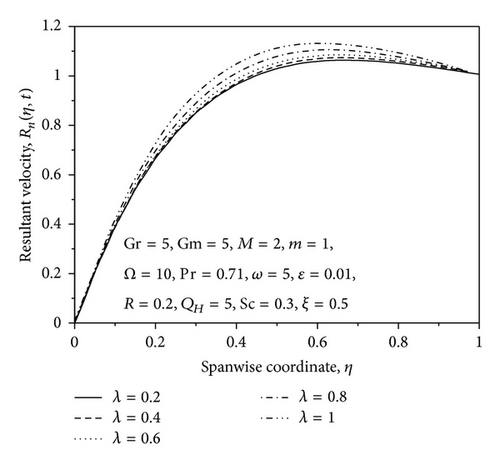
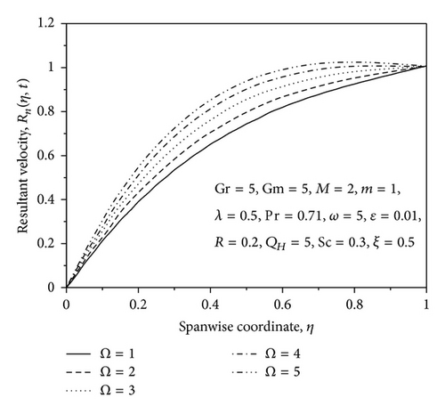
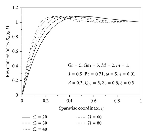
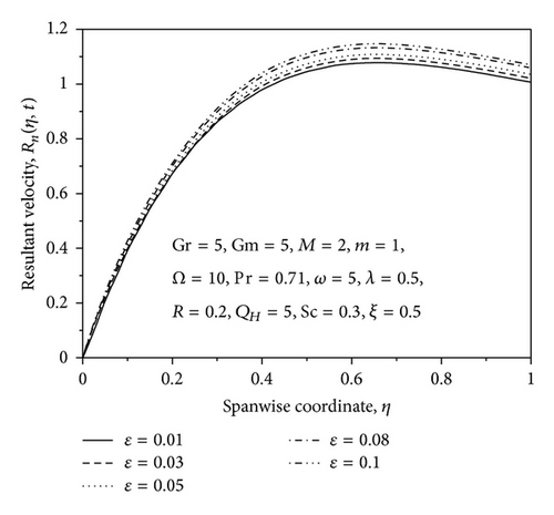
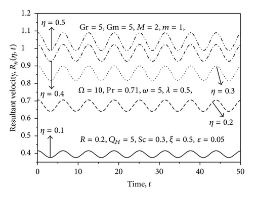
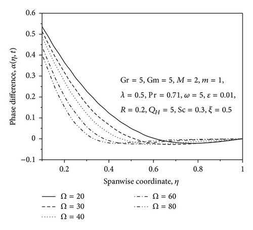
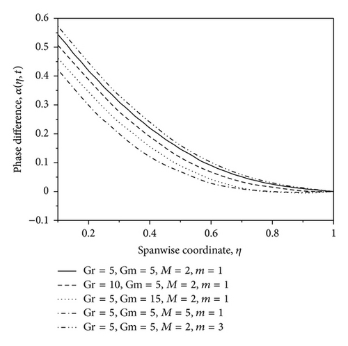
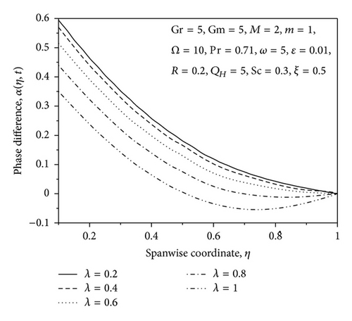
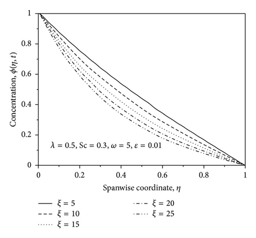
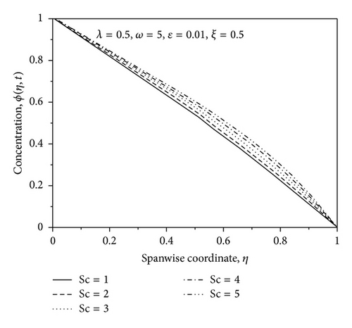
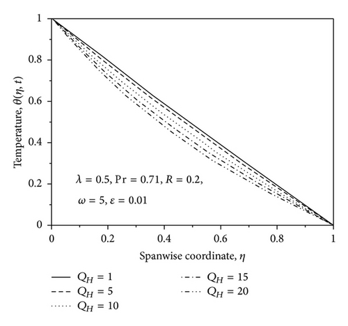
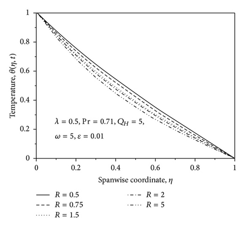
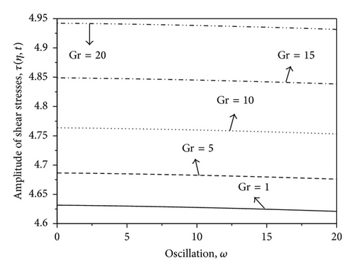
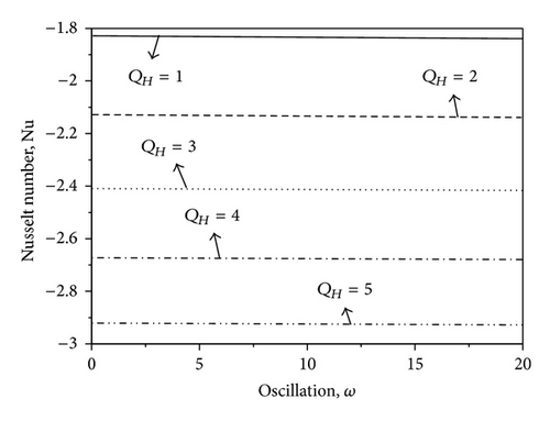
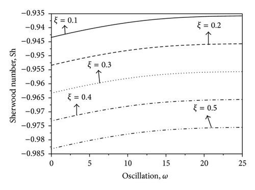
Table 1 shows a comparative study of the present results of amplitude and phase difference of shear stresses for the steady flow with those of Singh and Kumar [38]. It is seen from this table that the present results coincide very well with those of Singh and Kumar [38]. This confirms that the present analytical solutions are correct and accurate. Further, it is observed from this table that the effects of increasing the value of thermal Grashof number Gr, magnetic field M, and injection/suction parameter λ are to increase amplitude and decrease the phase difference of shear stresses for the steady flow, whereas reverse effect is found by increasing the Hall parameter, m. The effects of increasing the angular velocity Ω are to increase both amplitude and phase difference of shear stresses, whereas reverse effects are seen by increasing the values of the Prandtl number. The computed results τ0r, τ1r, β0, β1 for the present problem are provided in Table 2 for various values of Gm, R, QH, Sc, ξ, and m. It is seen from this table that the values of τ0r and τ1r increase whereas the values of β0 and β1 decrease with the increase of solutal Grashof number Gm, but the effects are reversed with an increase in the Hall parameter m, that is, the value of β0 and β1 are increased whereas there is decrease in the values of τ0r and τ1r. Also, it is found that the values of τ0r, β0β1 increase with an increase in the radiation parameter R. It is noted that the values of both τ0r and β0 increase due to an increase in the heat source parameter QH and chemical reaction parameter ξ, whereas the effects are reversed with the increase in the Schmidt number, that is, the values of τ0r, τ1rβ1 decrease with an increase in the Schmidt number. Also, it is found that the value of β1 decreases with an increase in the heat source parameter QH, chemical reaction parameter ξ and Schmidt number Sc.
| Gm | R | QH | Sc | ξ | m | τ0r | β0 | τ1r | β1 |
|---|---|---|---|---|---|---|---|---|---|
| 5.0 | 1.0 | 5.0 | 0.15 | 0.1 | 1.0 | 4.6540 | 0.6877 | 6.4123 | 0.7980 |
| 10.0 | 1.0 | 5.0 | 0.15 | 0.1 | 1.0 | 4.7299 | 0.6437 | 6.4542 | 0.7485 |
| 5.0 | 5.0 | 5.0 | 0.15 | 0.1 | 1.0 | 4.6543 | 0.6900 | 6.4094 | 0.8011 |
| 5.0 | 1.0 | 10.0 | 0.15 | 0.1 | 1.0 | 4.6545 | 0.6908 | 6.4219 | 0.8010 |
| 5.0 | 1.0 | 5.0 | 0.60 | 0.1 | 1.0 | 4.6534 | 0.6869 | 6.3805 | 0.8006 |
| 5.0 | 1.0 | 5.0 | 0.15 | 1.0 | 1.0 | 4.6541 | 0.6880 | 6.4132 | 0.7983 |
| 5.0 | 1.0 | 5.0 | 0.15 | 1.0 | 3.0 | 4.5464 | 0.7197 | 6.3064 | 0.8366 |
The profiles for resultant velocity Rn for the flow are shown in Figures 2–6 for suction/injection parameter λ and for small and large values of rotation parameter Ω, ϵ, and η, respectively. From Figure 2, it is observed that the increase in the suction parameter λ leads to an increase of Rn within the stationary plates. Similar trend of Rn profiles is seen by increasing the rotation parameter Ω, that is, resultant velocity profiles increase with increase in the rotation parameter Ω (small values) as shown in Figure 3. However, the opposite effect occurs near the right wall for large values of Ω as shown in Figure 4. This effect is due to the rotation effects being more dominant near the walls, so when Ω reaches high values, the secondary velocity component v decreases with increase in Ω while approaching to the right plate. From Figure 5, it is observed that the increase in the ϵ leads to an increase of Rn within the stationary plates. From Figure 6, it is seen that the resultant velocity profiles increases with increase in η; also it is observed that the velocity oscillates with increasing time. The phase difference α for the flow is shown graphically in Figure 7 for various values of rotation parameter Ω. From this figure, it is observed that the phase angle α decreases with an increase in rotation parameter. Figure 8 shows the variation of α against η for different values of thermal Grashof number Gr, solutal Grashof number Gm, Hartmann number M, and Hall parameter m. From this figure it is found that the values of α decrease with an increase in the value of Gr, Gm and M, whereas reverse trend is seen on the values of α by increasing the value of the Hall parameter m. The phase difference α for the flow is shown graphically in Figure 9 for various positive values of suction/injection parameter λ. The figure shows that the phase angle α decreases with the increase of suction parameter.
The effect of reaction rate parameter ξ on the species concentration profiles for generative chemical reaction is shown in Figure 10. It is noticed for the graph that there is a marked effect of increasing the value of the chemical reaction rate parameter ξ on concentration distribution ϕ in the boundary layer. It is observed that increasing the value of the chemical reaction parameter ξ decreases the concentration of species in the boundary layer; this is due to the fact that destructive chemical reduces the solutal boundary layer thickness and increases the mass transfer. Opposite trend is seen in the case when Schmidt number is increased as noted in Figure 11. It may also be observed from this figure that the effect of Schmidt number Sc is to increase the concentration distribution in the solutal boundary layer.
Figure 12 has been plotted to depict the variation of temperature profiles against η for different values of heat absorption parameter QH by fixing other physical parameters. From this graph, we observe that temperature θ decreases with increase in the heat absorption parameter QH because when heat is absorbed, the buoyancy force decreases the temperature profile. Figure 13 represents graph of temperature distribution with η for different values of radiation parameter. From this figure, we note that the initial temperature θ = 1.0 decreases to zero satisfying the boundary condition at η = 1.0. Further, it is observed from this figure that increase in the radiation parameter decreases the temperature distribution in the thermal boundary layer due to decrease in the thickness of the thermal boundary layer with thermal radiation parameter R. This is because large values of radiation parameter correspond to an increase in dominance of conduction over radiation, thereby decreasing the buoyancy force and the temperature in the thermal boundary layer.
Figures 14–16 show the amplitude of skin-friction, Nusselt number, and Sherwood number against frequency parameter ω for different values of Gr, QH and ξ, respectively. From Figure 14, it is observed that the skin friction increases with increasing the values of Gr. Also, the skin friction decreases slowly with increasing the value of ω. The amplitude of Nusselt number decreases with increasing the value of heat source parameter QH which is shown in Figure 15. Figure 16 shows the variation of Sherwood number with ξ and ω. From this figure, it is seen that the Sherwood number decreases with increasing the values of chemical reaction parameter ξ, and the opposite trend is seen with increasing the values of ω.
7. Conclusions
- (i)
An increase in QH leads to an increase in τ0r, β0, τ1r and decrease in β1.
- (ii)
An increase in radiation parameter R and chemical reaction parameter ξ leads to increase in τ0r, β0, and β1 but decrease in τ1r.
- (iii)
An increase in Gr, Gm, M, Ω, and λ leads to decrease in α0 and α1, whereas reverse effect is seen by increasing Hall parameter m.
- (iv)
The amplitude Rn increases with the increase of λ and Ω.
- (v)
The value of Rn decreases with the increase in chemical reaction parameter ξ and oscillation parameter ω.
- (vi)
The skin friction increases with increase in thermal Grashof number Gr.
Nomenclature
-
- C*:
-
- Dimensional concentration
-
- C0:
-
- Concentration at the left plate
-
- Cd:
-
- Concentration at the right plate
-
- cp:
-
- Specific heat at constant pressure
-
- d:
-
- Distance of the plates
-
- Dm:
-
- Chemical molecular diffusivity
-
- e:
-
- Electric charge
-
- g0:
-
- Acceleration due to gravity
-
- Gm:
-
- Modified Grashof number for mass transfer
-
- Gr:
-
- Modified Grashof number for heat transfer
-
- :
-
- Magnetic field
-
- H0:
-
- Magnetic field of uniform strength
-
- Hx:
-
- x-component of magnetic field
-
- :
-
- Current density
-
- Jx:
-
- x-component of current density
-
- k*:
-
- Mean absorption coefficient
-
- k1:
-
- Chemical reaction rate constant
-
- m:
-
- Hall parameter
-
- M:
-
- Hartmann number
-
- Nu:
-
- Nusselt number
-
- ne:
-
- Number density of the electron
-
- P*:
-
- Dimensional pressure
-
- pe:
-
- Electron pressure
-
- Pr:
-
- Prandtl number
-
- :
-
- Radiative heat flux
-
- Q0:
-
- Dimensional heat source
-
- QH:
-
- Heat source parameter
-
- R:
-
- Radiation parameter
-
- R0:
-
- Amplitude for steady flow
-
- Rn:
-
- Resultant velocity
-
- Rv:
-
- Amplitude for unsteady flow
-
- Sc:
-
- Schmidt number
-
- Sh:
-
- Sherwood number
-
- t*:
-
- Dimensional time
-
- T*:
-
- Dimensional temperature
-
- T0:
-
- Temperature at the left wall
-
- Td:
-
- Temperature at the right wall
-
- U0:
-
- Nonzero constant mean velocity
-
- u0:
-
- Primary velocity component for steady flow
-
- u1:
-
- Primary velocity component for unsteady flow
-
- :
-
- Electron velocity
-
- v0:
-
- Secondary velocity component for steady flow
-
- v1:
-
- Secondary velocity component for unsteady flow
-
- u*, v*, w*:
-
- Velocity components are in the x*-, y*-, z*-directions, respectively
-
- w0:
-
- Dimensional injection/suction velocity.
Greek Symbols
-
- α0:
-
- Phase difference for steady flow
-
- α1:
-
- Phase difference for unsteady flow
-
- α:
-
- Phase difference of the flow
-
- β:
-
- Coefficient of thermal expansion
-
- β*:
-
- Coefficient of solutal expansion
-
- β0:
-
- Phase difference of shear stresses for the steady flow
-
- β1:
-
- Phase difference of shear stresses for the unsteady flow
-
- β2:
-
- Phase difference of shear stresses for the flow
-
- δ:
-
- Phase difference of mass flux
-
- ϵ:
-
- Small positive constant
-
- η:
-
- Dimensionless distance
-
- γ:
-
- Phase difference of heat flux
-
- κ:
-
- Fluid thermal conductivity
-
- λ:
-
- Injection/suction parameter
-
- μ:
-
- Dynamic viscosity
-
- μe:
-
- Magnetic permeability
-
- ν:
-
- Kinematic viscosity
-
- ω:
-
- Oscillation parameter
-
- Ω*:
-
- Dimensional angular velocity
-
- Ω:
-
- Angular velocity
-
- ωe:
-
- Cyclotron frequency
-
- Φ:
-
- Amplitude of mass flux
-
- ϕ:
-
- Nondimensional concentration
-
- ρ:
-
- Density
-
- σ:
-
- Electric conductivity
-
- σ*:
-
- Stefan-Boltzmann constant
-
- τ:
-
- Amplitude of shear stresses for the flow
-
- τ0r:
-
- Amplitude of shear stresses for the steady flow
-
- τ1r:
-
- Amplitude of shear stresses for the unsteady flow
-
- τe:
-
- Electron collision time
-
- θ:
-
- Non-dimensional temperature
-
- Θ:
-
- Amplitude of heat flux.
Acknowledgment
One of the authors (Dulal Pal) is grateful to the University Grants Commission (UGC), New Delhi, for providing financial support under SAP-DRS (Phase-II) Grant.


