Realization of Colored Multicrystalline Silicon Solar Cells with SiO2/SiNx:H Double Layer Antireflection Coatings
Abstract
We presented a method to use SiO2/SiNx:H double layer antireflection coatings (DARC) on acid textures to fabricate colored multicrystalline silicon (mc-Si) solar cells. Firstly, we modeled the perceived colors and short-circuit current density (Jsc) as a function of SiNx:H thickness for single layer SiNx:H, and as a function of SiO2 thickness for the case of SiO2/SiNx:H (DARC) with fixed SiNx:H (refractive index n = 2.1 at 633 nm, and thickness = 80 nm). The simulation results show that it is possible to achieve various colors by adjusting the thickness of SiO2 to avoid significant optical losses. Therefore, we carried out the experiments by using electron beam (e-beam) evaporation to deposit a layer of SiO2 over the standard SiNx:H for 156 × 156 mm2 mc-Si solar cells which were fabricated by a conventional process. Semisphere reflectivity over 300 nm to 1100 nm and I-V measurements were performed for grey yellow, purple, deep blue, and green cells. The efficiency of colored SiO2/SiNx:H DARC cells is comparable to that of standard SiNx:H light blue cells, which shows the potential of colored cells in industrial applications.
1. Introduction
With the rapid development of photovoltaic (PV) industry, the decorative performance of solar modules gradually becomes an important issue, for instance, in building-integrated photovoltaics (BIPV) systems [1–3]. For industrial mass production multicrystalline silicon (mc-Si) solar cells, the front surface is usually covered by a layer of SiNx:H deposited by plasma-enhanced chemical vapor deposition (PECVD), which serves for both passivation and antireflection [4]. When the thickness and refractive index of the SiNx:H are optimized, the colors of solar cells look light blue. To realize colored solar cells, Tobias et al. reported a method by changing the thickness of the silicon nitride (n = 1.9) or zinc sulfide (n = 2.3), which acts as a single antireflection coating (ARC) on random pyramid textures [5]. However, this method results in significant Jsc losses. To improve the optical performance, multilayer ARC had been studied by simulation and experiments on polished surface [6, 7]. For pyramid texture surface, we have showed that it is possible for DARC colored cells to achieve equal Jsc to standard blue cell [8]. For acid texture, simulations and experiments on 3 × 3 cm2 mc-Si cells are under progress in our group [9]. Nevertheless, experimental reports on colored full dimensional industrial mc-Si cells with acid textures are still absent.
In this paper, we present our recent progress on simulations and experiments to fabricate colored mc-Si solar cells with a dimension of 156 × 156 mm2. In this study, we focus on using SiO2/SiNx:H DARC to replace the single SiNx:H layer, and using electron beam (e-beam) evaporation technique to deposit a layer of SiO2 over the standard SiNx:H after the conventional mc-Si cell fabrication. The solar cells with DARC stacks show various colors according to thickness of the SiO2 layer (top layer). Interestingly, the conversion efficiency of colored solar cells shows a little variation (+0.1% to −0.7%) compared to the reference cells with standard single SiNx:H layer.
2. Optical Simulation
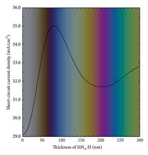
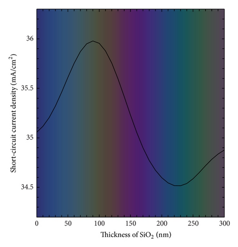
Figure 2(a) shows the simulated color and the Jsc of multicrystalline silicon solar cells as a function of the thickness of single SiNx:H ARC. As we can see, the peak of Jsc arrives with SiNx:H thickness of 80 nm, but then Jsc drops significantly when the thickness deviates from 80 nm. To achieve yellow, purple, and green colors, single ARC will suffer 2~3 mA/cm2 Jsc losses. For comparison, we simulated the case of SiO2/SiNx:H DARC, with the bottom layer fixed to SiNx:H (thickness = 80 nm, n = 2.1) and with the thickness of SiO2 (n = 1.46) varied from 0 nm to 300 nm as the top layer. Note that 0 nm SiO2 means the situation of optimal single layer SiNx:H. As shown in Figure 2(b), a slight boost of Jsc can be observed when the SiO2 thickness varies from 0 nm to 150 nm, while the color changes from light blue, to grey yellow, red, and purple. On the other hand, when the SiO2 thickness continues to increase to 300 nm, deep blue and green colors will appear, with a small Jsc losses of up to 0.5 mA/cm2. These indicate that the optical losses can be greatly suppressed with SiO2/SiNx:H DARC, comparing with the single SiNx:H ARC in Figure 2(a).
3. Experiments
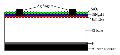
To further prove the simulations, experiments were carried out on industrial p-type mc-Si wafers with dimensions of 156 mm × 156 mm, and the wafer resistivity is between 1~3 Ωcm. After acidic texturing and cleaning, a standard POCl3 diffusion is performed in a quartz tube to form an emitter with sheet resistivity of 80 Ω/□. The samples were then coated with a SiNx:H layer in a PECVD (Roth&Rau) system. The deposition of SiNx:H was controlled to hold the refractive index of SiNx:H (n = 2.1) and its thickness of 80 nm. The metallizations are realized by screen printing to form the “H-pattern” front grid and full aluminum rear contact after firing. The I-V measurements were carried out with Berger I-V tester under calibration. To form the SiO2/SiNx:H DARC structure, SiO2 thin films were deposited by electron beam (e-beam) evaporation on the already fabricated solar cells. To avoid the deposition of SiO2 on the front side of the busbars, a steel mask was utilized as the shelter [13]. High purity SiO2 (99.99%) granules were used as the source material for evaporation and the source-to-substrate distance is 50 cm. E-type electron gun was employed for source evaporation. Ion bombardment was used to remove the dust on the substrate surface before deposition. The substrates were preheated and temperature was controlled at 200°C during the process. High purity oxygen (99.99%) was introduced into the chamber to maintain a pressure of 3.0 × 10⁻² Pa and used as reactive gas during the deposition. The deposition rate was controlled using a quartz crystal sensor placed near the substrate and was set to 2 Å/s. The deposition time was adjusted to modulate the thicknesses of the SiO2 as the top layer of 84 nm, 136 nm, 190 nm, and 220 nm, respectively. Six samples were fabricated for each thickness. The structure of the solar cell with SiO2/SiNx:H DARC is schematically shown in Figure 3.
The Fourier transformed infrared spectroscopy (FTIR) measurement for the SiO2 thin film has been made at 25°C using a Thermo-Nicolet 6700 FTIR spectrometer. The chemical states of the SiO2 were investigated by X-ray photoelectron spectroscopy (XPS) using an ESCALab250 (U.K) spectrometer with monochromatic Al Kα radiation (hν = 1486 eV). All binding energies were calibrated with respect to C 1s spectral line at 284.8 eV. The morphology of the surface was characterized by field emission scanning electron microscope (JEOL, JSM-6330F). The refractive indexes of the SiNx:H and SiO2 coatings were measured by a Sentech SE800 ellipsometer. The spectral reflectivity between 300 nm and 1100 nm was measured by a Hitachi U-4100 spectrophotometer. The quantum efficiency (QE) measurements were performed by a solar cell spectral response measurement system (PV measurement, QEX10). Finally, the I-V characteristics of the DARC solar cells were measured using a Berger I-V tester on a solar cell production line.
4. Results and Discussion
4.1. Films Characterization and Potential Stability
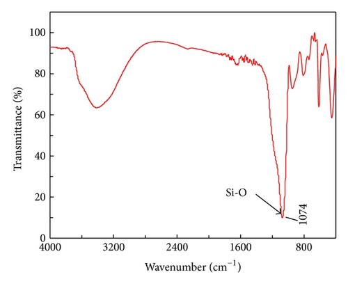
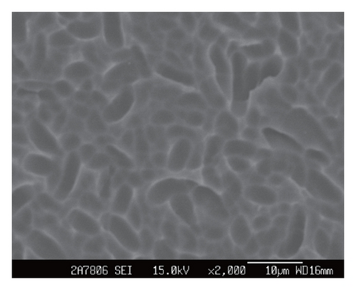
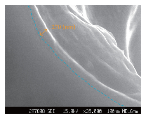
In order to get a qualitative spectra of SiO2 thin film compositions, we have performed Fourier transformed infrared spectroscopy (FTIR) analysis. The samples were deposited bifacially with the same film thicknesses on the polished silicon wafer. The spectra are presented in Figure 4. The band in the 1040–1150 cm−1 range is assigned to the stretching vibration mode Si–O [14, 15]. For the supplement of oxygen during the SiO2 deposition, a clear Si–O intensity peak (1074 cm−1) is observed for the SiO2 layer, which is related to the high oxygen content in this layer. The SEM images are shown in Figure 5. A clear concave-like acid texture can be seen in Figure 5(a), while the interface between silicon and SiO2/SiNx:H (deep blue color, with 80 nm SiNx:H and 190 nm SiO2) is illustrated in Figure 5(b).
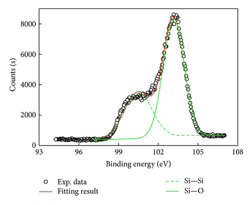
XPS was applied to determine the chemical state of the Si and O elements, which can confirm the presence of SiO2 layer in DARC. High-resolution spectra are shown in Figure 6(a) for Si 2p and Figure 6(b) for O 1s, respectively. The Si peaks were fitted using Gaussian curves. It is evident that two Si 2p peaks are located at 100.5 eV and 103.2 eV, as seen in Figure 6(a), which can be attributed to the signal of SiO2. It is recognized that the binding energy of Si 2p related to SiO2 is dependent on the oxygen composition [16]. Then, the films prepared by electron beam evaporation in this study were nearly stoichiometric silicon dioxide.

It is important that the surface of the solar cell endures various kinds of physical conditions. Structural stability of the antireflection coating is a key issue. SiNx:H films are widely used in photovoltaic industries due to their strong durability, excellent passivation properties, good dielectric characteristics, and resistance against corrosion by water. In our work, SiO2 thin films were deposited on the conventional solar cells with precoated SiNx:H single layer. The colored cells with SiO2/SiNx:H double layer antireflection coating do not need to suffer high temperature treatment again in the subsequent process, including encapsulation. For the SiO2/SiNx:H antireflection coating structure, due to different lattice spacing of substrate and silicon nitride layers, as well as stacking faults in the crystal structure, pin holes, or interstitial atoms, tension in deposited SiNx:H layers can occur, while SiO2 film exhibits compressing force. The opposite mechanical property can lead to the lower stress in the double layers. In addition, the thermal expansion coefficient of SiO2 is smaller than that of silicon; thus the interface stress in SiO2/SiNx:H is smaller than that of SiNx:H/SiO2 [17]. Consequently, such a good interface matching can avoid film cracks at the SiO2/SiNx:H interface. Besides, it has been confirmed that the SiNx:H and SiO2 films also have good thermal stability [18]. Hence, all the factors shown above are the main reasons why SiO2 is the best candidate to form double layer antireflection coatings with SiNx:H. On the other hand, for the deposition process of SiO2 on the conventional solar cells, the films properties are highly dependent upon both deposition parameters and subsequent processing. In order to obtain good thin film adhesion force on the substrate, we established the optimal process parameters to achieve high quality SiO2 films, which are transparent in the visible range and have less light absorption. The stability of SiO2 films, SiNx:H films, and SiO2/SiNx:H double films has been well investigated by many groups before [19–21]. For the SiO2/SiNx:H double layers, postanneal treatment can not only improve the optical property, but also decrease residual stress. Based on above discussion, we believe the SiO2/SiNx:H structure has superior stability, which can be used in the colored solar cells.
4.2. Optical Characterization
Figure 7 presents the photographs of the fabricated DARC mc-Si solar cells (156 mm × 156 mm) samples with SiO2 thickness equal to 84 nm (grey yellow), 136 nm (purple), 190 nm (deep blue), and 220 nm (green) covering on 80 nm SiNx:H (light blue). It is apparent that colored cells are achievable by varying the thickness of SiO2 (top layer) on the solar cell with SiNx:H (bottom layer). For the whole cells, the color is basically uniform. However, small chromatic aberrations in the edges still can be observed, which indicated that higher spatial uniformity during the deposition is required for further improvements.
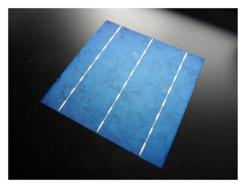
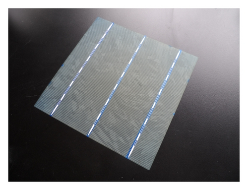
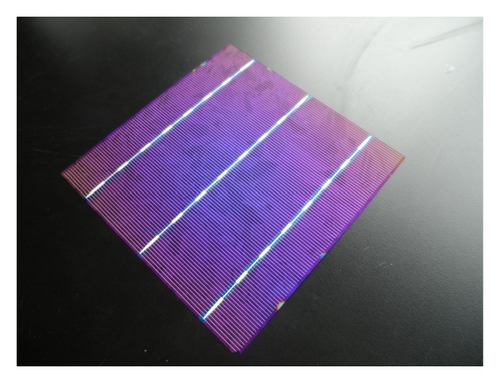
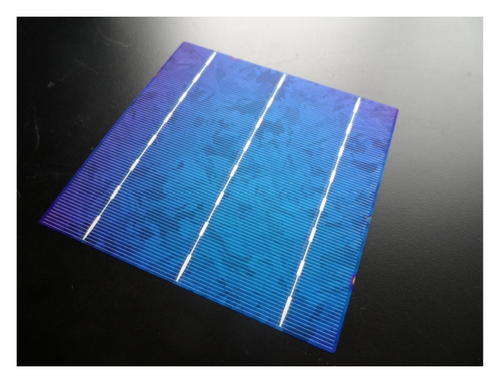
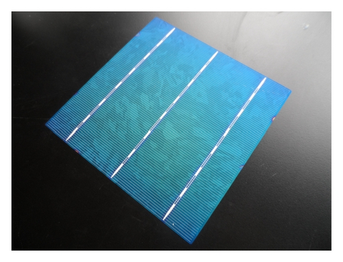
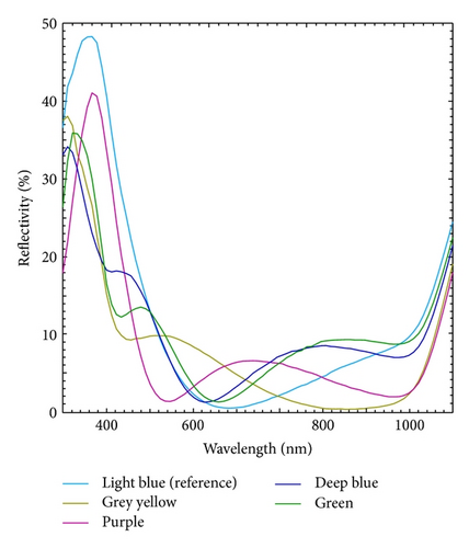
Figure 8 depicts the reflectivity of single layer SiNx:H with optimized thickness of 80 nm, as well as with the reflectivity of SiO2/SiNx:H DARC for optimized grey yellow, purple, deep blue, and green cells. As shown in Figure 8, the hunches of reflectivity move gradually from short wavelength to long wavelength, which explained the color switch by increasing the thickness of SiO2.
4.3. I-V Characteristics of Colored Solar Cells
All I-V parameters presented in the study are averaged with six samples of each group. All measurements were conducted under the standard test conditions (AM 1.5G spectrum, 100 mW/cm2, 25°C). Prior to the measurements, the simulator was calibrated with a reference multicrystalline silicon solar cell, which was calibrated by the Fraunhofer ISE. Table 1 summarizes the average performance parameters of colored mc-Si solar cells, compared to the standard light blue cells with 80 nm single SiNx:H. As shown in Table 1, the FF of each group is nearly the same, while the Voc shows small degradation for colored cells, which probably caused by the surface damages introduced during the e-beam evaporation. The main power loss of colored cell comes from the Jsc losses, which reflects that the optical losses are still the dominating efficiency limit for colored solar cells. However, we demonstrate that comparable cell efficiency of colored solar cell is available, comparing to standard light blue cell, and 16.97% efficiency for grey yellow cell (abs. 0.1% higher than standard cell) with Voc of 618.6 mV, Jsc of 35.77 mA/cm2, and FF of 76.66% when SiO2 (84 nm)/SiNx:H (80 nm) DARC is applied.
| Samples | Color | Eff. (%) | FF (%) | Jsc (mA/cm2) | Voc (mV) |
|---|---|---|---|---|---|
| SiNx : H (80 nm) (reference) | Light blue | 16.87 | 76.89 | 35.18 | 623.6 |
| SiO2 (84 nm)/SiNx : H (80 nm) | Grey yellow | 16.97 | 76.66 | 35.77 | 618.6 |
| SiO2 (136 nm)/SiNx : H (80 nm) | Purple | 16.75 | 77.07 | 34.91 | 622.4 |
| SiO2 (190 nm)/SiNx : H (80 nm) | Deep blue | 16.13 | 76.93 | 33.86 | 619.2 |
| SiO2 (220 nm)/SiNx : H (80 nm) | Green | 16.43 | 77.05 | 34.30 | 621.6 |
4.4. Colored Solar Cell Module Simulation
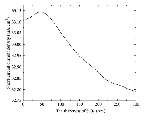
The matching ARC to refraction index of the cover materials in a module is one of the key factors that ultimately determine the optical properties of PV modules. To investigate the behaviors of solar cells with double layer antireflection coatings after encapsulation, we simulated the module Jsc by Monte Carlo ray tracing method. EVA was considered as the encapsulation material in the simulation since currently it is the most widely used with the refractive index of approximately 1.5 at 633 nm. Since the multiple total internal reflections between glass and air were neglected, the Jsc was underestimated slightly.
As shown in Figure 9, the Jsc is equal to 33.11 mA/cm2 when the thickness of SiO2 is 0 nm, which is the case of single layer SiNx:H ARC. As the SiO2 thickness increases from 0 nm to 50 nm, Jsc increases slightly and reaches the maximum value, and then the Jsc experienced a slow decrease; it drops to 32.78 mA/cm2 when the thickness of SiO2 is 300 nm. In overall, the advantages of DARCs are more limited in modules with EVA than in cells. This is mainly because the glass and EVA have a refractive index which is very close to SiO2, and EVA has strong absorptivity in short wavelength. Therefore, the suppression of reflectivity in short wavelength via DARCs is not so notable anymore. Better encapsulation materials (such as PVB, silicone resin, and high transmittance glass) are needed to obtain high-performance module for the BIPV [22]. Additionally, the NICE (New Industrial Solar Cell Encapsulation) module concept [23, 24] seems to be a better option. Contrary to standard modules, NICE modules do not use EVA-like encapsulants. The use of nitrogen instead of EVA avoids any UV-cut from the incident spectrum that is typically observed with standard encapsulants. Further researches for this subject are now under investigation to optimize the module conversion efficiency.
5. Conclusions
- (1)
Various colors can be achieved by adjusting the thickness of SiO2.
- (2)
The cells conversion efficiencies are very comparable, which indicates the potential of a smaller mismatch for colorful modules fabricated with cells of different colors.
- (3)
Small degradations of Voc are found after the deposition of SiO2, which indicated that only little surface damage is caused by e-beam evaporation.
Therefore, more accurate e-beam evaporation process controls are needed for further works to improve the uniformity and reduce the surface damages. With SiO2/SiNx:H DRAC, colored mc-Si solar cells with comparable cell efficiencies are available for industrial applications, for instance, in architectural integration in buildings.
Acknowledgments
The authors would like to thank the National Natural Science Foundation of China (Grant nos. 61076059 and 60906005) and National High-Tech Research and Development Program of China (863 Program, Grant no. 2012AA050302) and Guangdong Key Science & Technology Project 2010 (no. 2010A080805003) for financial support.


