Negative Propagation Effects in Two-Dimensional Silicon Photonic Crystals
Abstract
We demonstrated negative refraction effects of light propagating in two-dimensional square and hexagonal-lattice silicon photonic crystals (PhCs). The plane wave expansion method was used to solve the complex eigenvalue problems, as well as to find dispersion curves and equal-frequency contour (EFC). The finite-difference time-domain (FDTD) method was used to simulate and visualize electromagnetic wave propagation and scattering in the PhCs. Theoretical analyses and numerical simulations are presented. Two different kinds of negative refractions, namely, all-angle negative refraction (AANR) without a negative index and negative refraction with effective negative index, have been verified and compared.
1. Introduction
At the beginning of the 21st century, a new type of artificial material that displays anomalous properties in their interactions with electromagnetic waves has attracted a significant degree of scientific interests. These media are commonly known as “negative index materials” (NIMs) (or left-handed materials, LHMs), since its permittivities and permeabilities are simultaneously negative. NIMs can be exploited for use in a wide variety of guiding and radiating structures, such as absorber, filter, coupler, antenna, superlens, and superprism. The direction of phase velocity of light wave propagating inside such a material is opposite to the direction of its energy flow. It means that the Poynting vector and wave vector are antiparallel; therefore negative refraction occurs at the interface [1]. Veselago first pointed out the negative refraction phenomena in 1968 [2]. Years later, many theoretical and experimental groups have investigated left-handed materials [3–5].
Since PhCs are more feasible to fabricate in optical region than negative index materials [6], effective-negative-index PhCs attracted tremendous interest of electrical engineers and physicists. One of the most prominent properties of negative index PhC is its capability of amplification of evanescent waves. Light propagating in such PhCs may exhibit negative refraction near the photonic bandgaps, such as mirror-like effect, image-transfer effect, and superprisming effect [7–12]. The effective refraction index of such PhC, which is analogous to the effective mass in solid state physics [13], is controllable by the band structure of the material. Notomi studied negative refraction in strongly modulated PhCs near the photonic bandgaps [14]. Moussa et al. investigated superlensing behavior in 2D PhC [15]. Cubukcu et al. demonstrated experimentally single beam negative refraction and superlensing in the valence band of 2D PhCs operating in the microwave regime [16]. Berrier et al. presented an experimental verification of negative refraction for infrared wavelength in an effective-negative-index PhC [17]. Zhang proposed a 2D metal-core PhC, which can achieve effective negative indexes for both TE and TM modes [18]. Lu et al. demonstrated an imaging experiment by using a slab of an effective-negative-index PhC in microwave region [19].
It was demonstrated that negative refraction phenomena in PhCs are possible in regimes of negative group velocity and negative effective index above the first band near the Brillouin zone center Γ [20]. Negative refraction can also be resulted from some special EFC in the first band of PhC [21]. The frequencies in the lowest band may be more desirable in high-resolution superlensing.
In this paper we study two different kinds of negative refraction at the first band and the second band, respectively. Firstly we study AANR without a negative index, which is resulted from a special EFC near the Brillouin zone corner M in the first band of a square-lattice silicon PhC. Secondly, the negative refraction with effective negative index is investigated, which happens in regime of negative group velocity and negative effective index near the Brillouinzone center Γ in the second band of a hexagonal-lattice silicon PhC. The plane wave expansion method is used to solve complex eigenvalue problems. The photonic band structures and equifrequency surfaces are calculated, and two different negative refraction frequency ranges are found in two different types of PhC lattices. The finite-difference time-domain (FDTD) method is employed to simulate and visualize the subwavelength imaging effects.
2. All-Angle Negative Refraction without a Negative Index
In this part we consider an AANR effect that does not employ a negative effective index of refraction in the PhCs. In the first band of a square-lattice PhC, the EFC is not necessarily a circle around Γ point, but a convexity around M point for certain frequency (as shown in Figure 2). So no effective refractive index can be defined in such PhCs. This kind of PhCs is referred to as AANR PhCs.
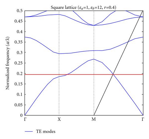
We begin with TE modes (in-plane electric field vector) and consider a square lattice of air holes in silicon host material with ε = 12. The hole radius r = 0.4a, where a is the lattice constant. Firstly, we employ the plane wave expansion method to calculate the AANR frequency range in our model system. The band curves for TE polarization is shown in Figure 1. It is identified that the AANR region occurs in the vicinity of ω = 0.211(2πc/a). The upper frequency limit is determined directly by the intersection of the first band curve with the light line. The lower frequency limit is determined by the frequency at which radius of the curvature of the contours along ΓM becomes divergent (as shown in Figure 2(b)).
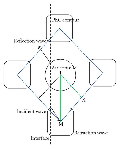
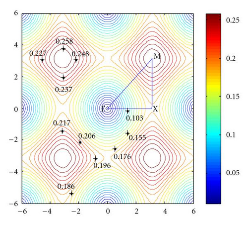
The contours of dispersion of the first band, drawn in the first Brillouin zone, are shown in Figure 2(a), where the thick arrows represent directions of group velocity, and thin arrows stand for directions of phase velocity. The EFCs of the actual PhC are shown in Figure 2(b). AANR occurs at frequencies that correspond to all-convex contours with a negative photonic effective mass. If the air-PhC interface normal is along the Γ-M direction, and the contour is everywhere convex, an incoming plane wave from air will couple to a single mode that propagates in this PhC on the negative side of the boundary normal.
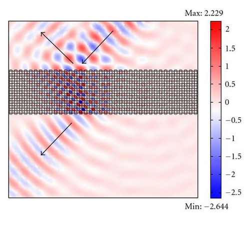
Figure 3 shows the negative refraction of a light beam across a square-lattice 2D PhC slab. The incoming wave with normalized frequency of ω = 0.211(2πc/a) is incident from up right side with an angle of 45° with respect to the normal (as shown by the arrows). The refracted light inside the slab is on the right side of the normal. On its arrival at the lower surface of the slab, negative refraction happens again. The outgoing beam has the same propagation direction as the incoming beam but with a negative transverse shift.
AANR is essential for superlensing applications. The existence of AANR effect implies that there is essentially no physical limit on aperture of the imaging system. Such a superlens possesses several key advantages over conventional lenses. To realize AANR for superlensing, the required conditions for our model system are that the EFCs should be both convex and larger than the EFCs for air (circles with radius ω/c). Incident beams at any incident angle will then experience negative refraction when entering the PhC. Thickness and finishing of the surfaces of the PhC slab should be chosen carefully to minimize reflections. Moreover, when air holes (or dielectric rods) are cut in half at the terminating surfaces, surface mode can come to exist on the slab. The transmission of evanescent waves can be amplified through the excitation of surface modes in a slab of PhC, which plays a very important role in subwavelength imaging.
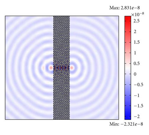
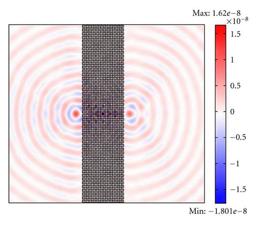
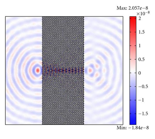
Shown in Figure 4 are the FDTD simulations of a continuous-wave point source in front of a PhC slab of square lattice. The radiation is TE polarized at frequency ω = 0.211(2πc/a). The slabs in Figures 4(a)–4(c) are, respectively, 8 layers, 12 layers, and 20 layers thick. The distances of point sources to the left-hand side surfaces of the slabs are respectively, 1.5a, 2a, and 3a. It is seen that an image of the point source is formed in each case at, respectively, a distance of 1.5a, 2a, and 3a away from the right-hand side surface of the superlens. Although small aberrations are visible in the field patterns, the simulations clearly demonstrate that superlensing effect occurs in these PhC slab systems. An infinitely long slab can focus all the Fourier components of a subject within this frequency range (including both propagation waves and evanescent waves), so that to produce a perfect image [22]. The flat lens property of AANR PhCs has many important potential applications, such as high-capacity optical storage systems [23].
3. Negative Refraction with Effective Negative Index
Distinguished from AANR PhCs, there is another kind of PhCs that can also give rise to negative refraction. It is referred to as effective-negative-index PhCs. In this part we consider the negative refraction property of PhC of 2D hexagonal lattices that are made of air holes. The background material is silicon (ε = 12), and the radius of the air holes is 0.4a, where a is the lattice constant. The band curves for TM polarization (in-plane magnetic field vector) are shown in Figure 5. A negative refraction region is identified in the vicinity of ω = 0.31(2πc/a) where the second band curve and the light line intersect.

Shown in Figure 6 are EFCs of TM mode for the normal frequency range between ω = 0.260(2πc/a) and ω = 0.360(2πc/a). The shapes of EFCs for the second band are almost circular in the frequency range between ω = 0.300(2πc/a) and ω = 0.360(2πc/a), where higher frequency contours concentrate near the Γ point (the center of circles). The blue dotted circle is the line of intersection of the second band surface and the light cone. The radius of the dotted circle is equal to the radius of EFC of air cone at ω = 0.315(2πc/a).
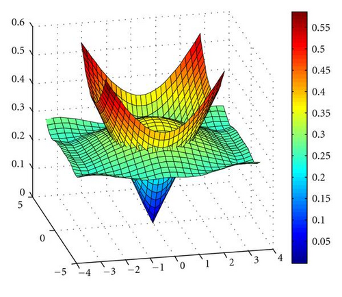
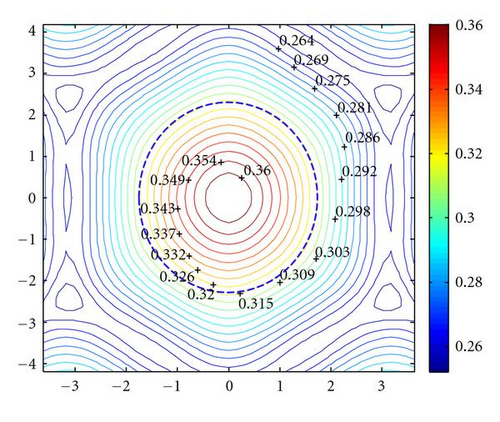
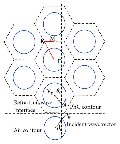
The EFC of frequency ω = 0.315(2πc/a) is plotted in Figure 7. Light of this frequency is incident from air (n = 1) into the model PhC that has an effective negative index neff (as shown in Figure 7). In the PhC, the energy velocity vector coincides with the group velocity vector of the Bloch mode Vg = ∇kω. A Bloch mode denoted by A is excited in the PhC along the direction perpendicular to the EFC and point to Γ. Given the conservation of tangential wave vector, negative refraction occurs at the interface between air and PhC.
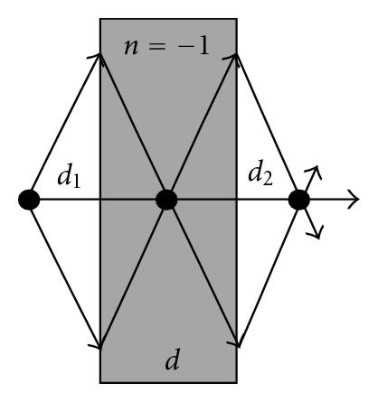
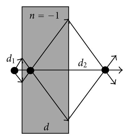
The homogeneity of refractive index of a PhC with effective negative index can be judged by its property of imaging as a flat lens. An isotropic homogeneous medium with refractive index of n = −1 creates an image of a point source on the other side of the slab at a distance which depends on the distance of the source to the slab. The relation between source distance and image distance is illustrated directly from the simple ray diagram in Figure 8. There is no reflection at the interface between a negative index material of n = −1 and air (n = 1). The coupling coefficient for any incident angle is always 100%. On the other hand, for a PhC with effective negative index of neff = −1, the situation is slightly different. The FDTD simulations of imaging capability of a PhC slab with effective negative index of neff = −1 are shown in Figure 9. The imaging property is similar to that of the isotropic homogeneous medium with refractive index of n = −1. It is found that the image distance varies with the source distance in a similar way, with the sum of source distance, and image distance equals thickness of the PhC slab. On the other hand the transmission rate at the air-PhC interfaces in this case is highly angular dependent [24]. Incident wave cannot couple completely to the PhC. This is evident in Figure 9, where the field on the right-hand side of the slab is weaker than that on the left-hand side. From these simulations it can be concluded that the proposed PhC is not an isotropic homogeneous medium.
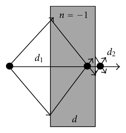
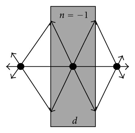
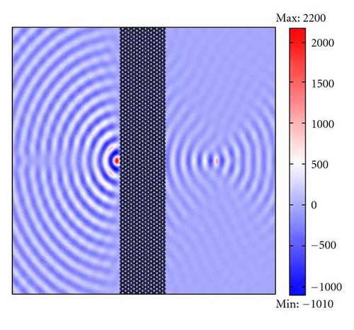
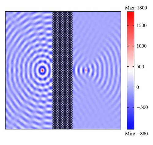
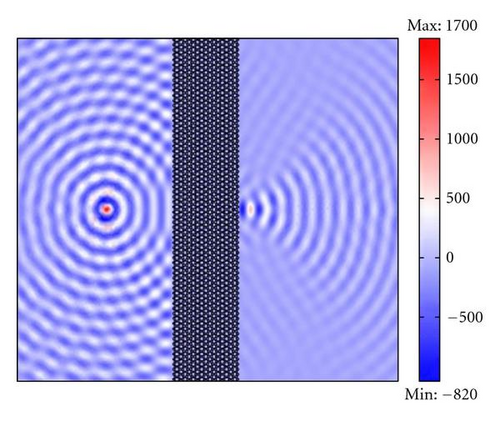
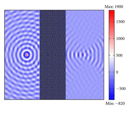
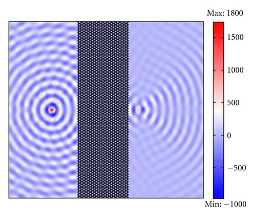
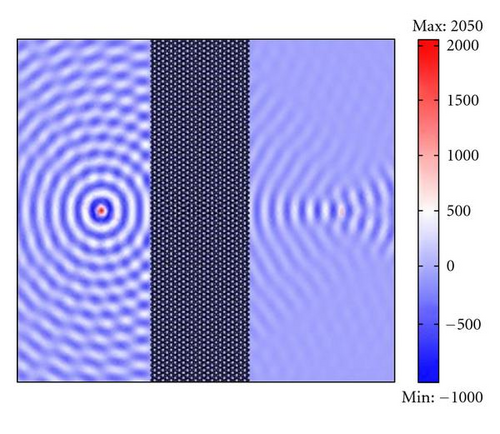
To examine the frequency dependence of effective negative index neff, we employ the FDTD method to simulate imaging of a point source of different frequency by a finite-width PhC slab. The results shown in Figure 10 indicate that source of different frequency is focused to a different position. The point source locates at a fixed position in air, with a distance to the slab being half of the slab thickness. For the dispersive case of ω0 = 0.315(2πc/a) which corresponds to the aforementioned neff = −1, the image distance outside the slab is equal to the source distance as shown in Figure 10(a). For a lower frequency ω1 = 0.300(2πc/a) which corresponds to neff < −1, the image distance is slightly shorter than the source distance as shown in Figure 10(b). On the other hand, for a higher frequency ω2 = 0.320(2πc/a) which corresponds to neff > −1, the image distance is slightly longer than the source distance as shown in Figure 10(c).
4. Conclusions
In this paper we demonstrated two types of negative refraction mechanisms of PhC, namely the all-angle negative refraction without a negative index and the negative refraction with effective negative index. Light focusing effect occurs in both PhC slab systems. The AANR PhC slab can focus all Fourier components of an image within the frequency range of negative refraction. In the PhC with effective negative index, negative refraction has high angular dependence. The AANR PhC is more suitable for high-resolution superlensing application.
Acknowledgments
This work is supported by the National Natural Science Foundation of China under Grant no. 60588502. One of the authors (P. Jiang) would like to thank her parents and husband for understanding and spiritual support.


