Upscaling of Permeability Field of Fractured Rock System: Numerical Examples
Abstract
When the permeability field of a given porous medium domain is heterogeneous by the existence of randomly distributed fractures such that numerical investigation becomes cumbersome, another level of upscaling may be required. That is such complex permeability field could be relaxed (i.e., smoothed) by constructing an effective permeability field. The effective permeability field is an approximation to the real permeability field that preserves certain quantities and provides an overall acceptable description of the flow field. In this work, the effective permeability for a fractured rock system is obtained for different coarsening scenarios starting from very coarse mesh all the way towards the fine mesh simulation. In all these scenarios, the effective permeability as well as the pressure at each cell is obtained. The total flux at the exit boundary is calculated in all these cases, and very good agreement is obtained.
1. Introduction
The first level of upscaling encountered when studying phenomena occurring in porous media is related to adopting the continuum hypothesis to such complex formations. That is moving from pore scale simulations in which variables are only defined within the fluid region to the continuum description in which macroscopic variables are defined everywhere in the simulation domain. In doing so, certain conditions and length scale constraints need to be fulfilled in order to generate macroscopic quantities that are scale independent [1]. While these length scale constraints may be easily adopted in statistically homogeneous porous media, it may be difficult to satisfy particularly closer to the interface boundaries between media with very different textures [2]. Unfortunately, these sharp interface boundaries are ubiquitous in rock systems which apparently contain several fractures and fissures. These fractures have significant effects on both flow and transport in porous media. They provide fluids and solutes with significantly less resistance paths compared with the surrounding matrix and therefore can lead solutes to reach further distances than what simulations ignoring them would normally predict. There are two approaches to dealing with these fractures depending on their density and distributions in rock systems. For rock systems with few penetrating fractures, it is customary to consider the discrete fracture model (e.g., [3, 4]). In this model, fractures are assumed as two-dimensional surfaces impeded within the given rock matrix domain. These fracture surfaces have their own properties and equations which include interaction terms between the rock matrix and the fractures. When the numbers of the fractures are large and their geometrical distributions are complex such that it becomes exceedingly difficult to consider them in simulation, another alternative is to construct an equivalent porous medium domain by further increasing the averaging representative volume. In this approach, one abandons the fractures and considers another continuum, coarser in nature, but may be acceptable for our engineering application and design.
In terms of simulation, although the discrete fracture model provides an elegant way to deal with fractures when their density is manageable, the drawback of this approach, however, is the fact that the interaction term between the fracture and the surrounding rock matrix is, in most cases, not known and ends up as a fitting parameter. The other approach is to refine the mesh all the way to the fractures level, which apparently poses enormous difficulties in large systems particularly when modeling complex transport problems like multiphase compositional flows. It has been, therefore, proposed that an even higher level of upscaling may be required to generate field properties to reduce the required computing resources and provide certain requirements satisfaction. These requirements are related to the fact that the solution of the upscaled system should produce approximately close results to those obtained from simulating the real system. That is if the permeability field may be relaxed such that the sharp interface boundaries may be smoothed, in a sense, the requirements for denser mesh closer to the sharp interface boundaries may be abandoned, and it may be possible to significantly decrease the number of degrees of freedom of the system. Different approaches have been considered in the literatures based on either deterministic approaches (e.g., [5–13], etc.) or stochastic approaches (e.g., [14–18], etc.). In the next section we introduce a quick review of the previous work emphasizing on two methods which are related to this work closely.
2. Investigation of the Upscaling Techniques
3. The Subdomain Technique
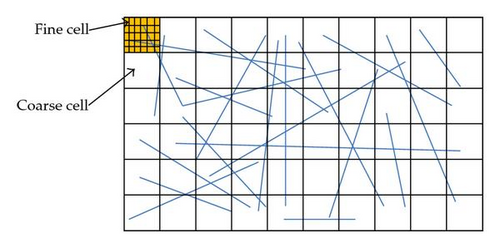
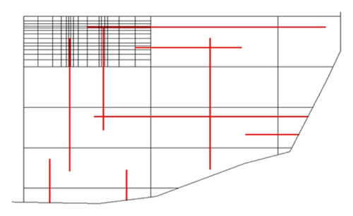
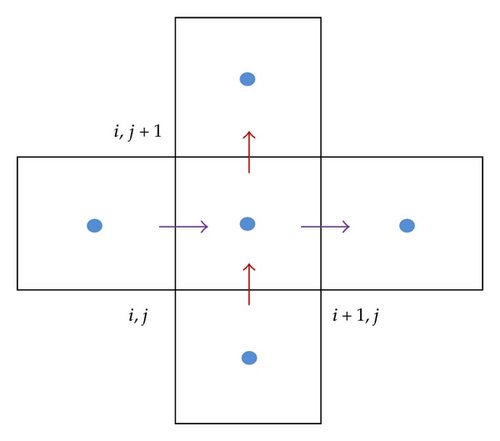
We apply the local-local method to obtain the effective permeability field for a given complex permeability field in fractured rock system. The simulation domain represents a rectangular two-dimensional area with a set of randomly generated fractures. We use the cell-centered finite difference scheme (CCFD) to approximate the governing equations because it satisfies mass conservation law locally. Furthermore, we consider the fractures oriented horizontally and vertically, as shown schematically in Figure 2. The local-local method deals with each macroscopic cell separately. For this purpose, we define two different meshes; the first mesh is the coarse mesh and it is defined globally over the whole simulation domain, and the second mesh is fine according the complexity of the permeability field within each coarse cell. That is we construct the coarse rectangular mesh over the whole simulation domain, {X0, X1, X2, …, Xi, …, Xm} × {Y0, Y1, Y2, …, Yj, …, Yn}, and for each coarse mesh we construct a finer mesh given as {x0, x1, x2, …, xi, …, xp} × {y0, y1, y2, …, yj, …, yq}.
4. Discretization of the Governing Equations
5. Application of the Local Upscaling Technique to Fractured Rock System
- (i)
Discretize the whole domain with the appropriate fine mesh based on the complexity of the permeability field and fractures structure.
- (ii)
Discretize the whole domain with the required coarse mesh that conforms with the fine mesh (i.e., the mesh coincides with the fine mesh).
- (iii)
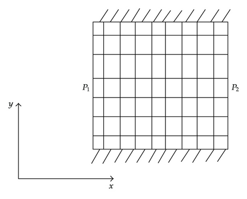
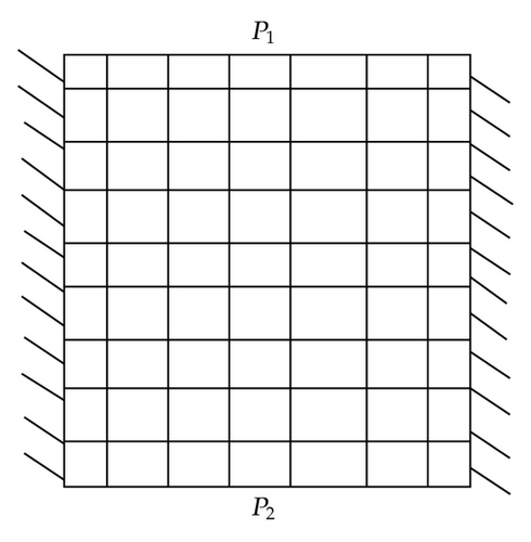
For each coarse cell, solve the boundary value problem given by (2.3) over the finer cells subject to predefined boundary conditions. That is to get the effective permeability in the x and y-directions, Kxx and Kyy, we consider two cases as shown in Figure 4. For example, in Figure 4(a), we consider a no-flow boundary condition at the top and bottom boundaries and prescribed pressure boundary condition (say p1 = 1 and p2 = 0) at the other two sides. Similar boundary conditions are suggested in Figure 4(b). The velocity at the finer scale could then be calculated.
- (iv)
Using (2.6), one may calculate the x and y-velocity at the center of the faces of the coarse cell which encompass the finer mesh.
- (v)
These velocities can then be used to calculate the effective permeability components in x and y directions with the Darcy’s equation (2.2).
6. Numerical Examples
6.1. Example 1: One Fracture in Both the Horizontal and Vertical Directions
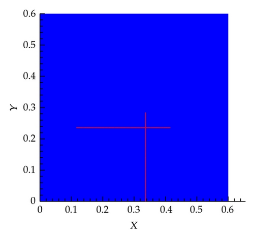
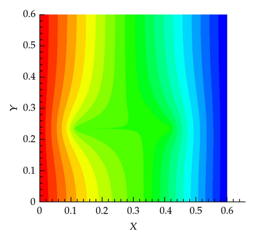
In this scenario, two fractures are generated randomly as shown in Figure 5(a). The pressure field for this system obtained by solving the governing equations using the fine mesh is shown in Figure 5(b), from which we can see the apparent influence of the fractures in distorting the pressure field.
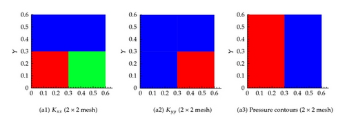
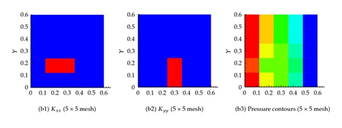
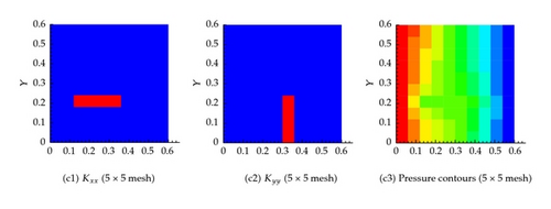
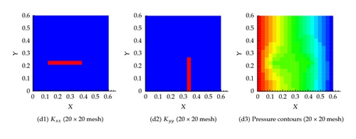
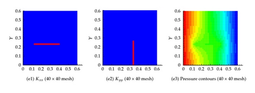
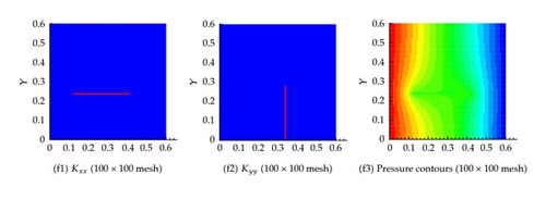
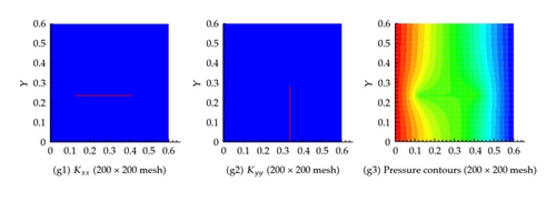
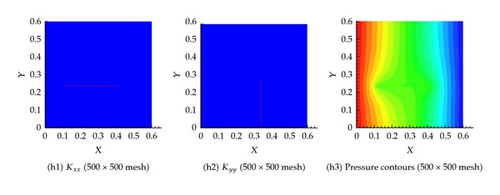
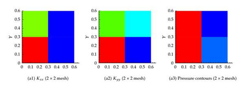
Several coarsening scenarios are considered, namely, 2 × 2, 5 × 5, 20 × 20, 40 × 40, 100 × 100, and 500 × 500. In all these scenarios, the requirement that the flux across any surface calculated using the fine mesh and any other coarse mesh is the same. The generated effective hydraulic conductivity of each cell, and , for different resolution scenarios is shown in Figure 6. Apparently, the permeability of the cells containing fractures is larger. Furthermore, as the resolution of the mesh increases, the permeability contrast sharpens around the fractures. Figure 6 also shows the pressure at the center of each cell for the different resolution scenarios. It is apparent that the pressure field gets closer to the fine scale simulation as the resolution increases. On comparing the flux at the exit boundary (Table 1), it is clear that the flux for different coarsening scenario is close to one another.
| 2 fractures | 10 fractures | 40 fractures | 800 fractures | |
|---|---|---|---|---|
| Reference (fine mesh) | 1.238536e − 03 | 1.140093e − 03 | 1.784033e − 03 | 4.037607e + 00 |
| Upscaled (2 × 2) | 1.2060398e − 03 | 1.1671849e − 03 | 1.7678765e − 03 | 4.0482439e + 00 |
| Upscaled (5 × 5) | 1.2279665e − 03 | 1.1480335e − 03 | 1.6639357e − 03 | 4.0201914e + 00 |
| Upscaled (10 × 10) | 1.2305291e − 03 | 1.1357165e − 03 | 1.6719508e − 03 | 4.0624327e + 00 |
| Upscaled (20 × 20) | 1.2377141e − 03 | 1.1567826e − 03 | 1.7251369e − 03 | 4.0636998e + 00 |
| Upscaled (40 × 40) | 1.2329549e − 03 | 1.1414539e − 03 | 1.7356198e − 03 | 4.0958317e + 00 |
| Upscaled (60 × 60) | 1.2330102e − 03 | 1.1364853e − 03 | 1.7344252e − 03 | 3.9842654e + 00 |
| Upscaled (80 × 80) | 1.2312922e − 03 | 1.1368569e − 03 | 1.7406374e − 03 | 4.0324003e + 00 |
| Upscaled (100 × 100) | 1.2368716e − 03 | 1.1353105e − 03 | 1.7651864e − 03 | 4.0198896e + 00 |
| Upscaled (160 × 160) | 1.2354428e − 03 | 1.1366243e − 03 | 1.7682102e − 03 | 3.9614817e + 00 |
| Upscaled (200 × 200) | 1.2376183e − 03 | 1.1376407e − 03 | 1.7735081e − 03 | 4.0495773e + 00 |
| Upscaled (240 × 240) | 1.2366092e − 03 | 1.1380291e − 03 | 1.7735767e − 03 | 3.9653353e + 00 |
| Upscaled (300 × 300) | 1.2393249e − 03 | 1.1413561e − 03 | 1.7762217e − 03 | 3.9176552e + 00 |
| Upscaled (400 × 400) | 1.2368358e − 03 | 1.1370930e − 03 | 1.7671836e − 03 | 3.7225614e + 00 |
| Upscaled (500 × 500) | 1.2378015e − 03 | 1.1405213e − 03 | 1.7877663e − 03 | 4.0850977e + 00 |
6.2. Example 2: Five Fracture in Both the Horizontal and Vertical Directions
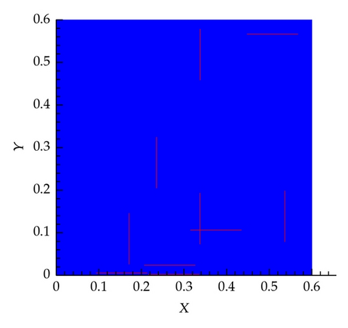
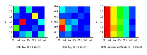
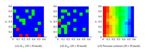
In this scenario, five fractures are generated randomly in both the horizontal and vertical directions (i.e., 10 fractures in total), as shown in Figure 7(a). The pressure field for this system as obtained by solving the governing equations using the very fine mesh is shown in Figure 7(b). Again, the influence of the fractures in distorting the pressure field is significant.
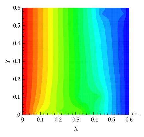
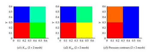
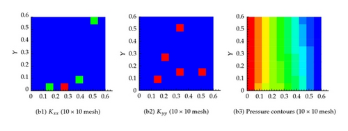
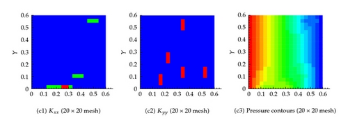
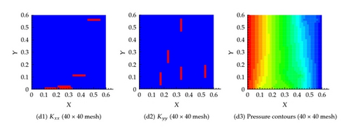
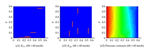
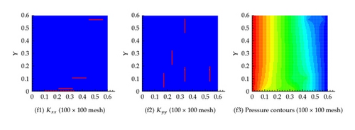
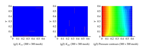
Effective permeability in each cell is shown in Figure 8, which shows that the effective permeability approaches that of the fine mesh simulation as the number of grid cells increase. Again the flux at the exit boundary is very close to the different coarsening scenarios as depicted in Table 1.
6.3. Example 3: Twenty Fractures in Both the Horizontal and Vertical Directions
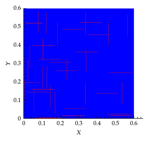
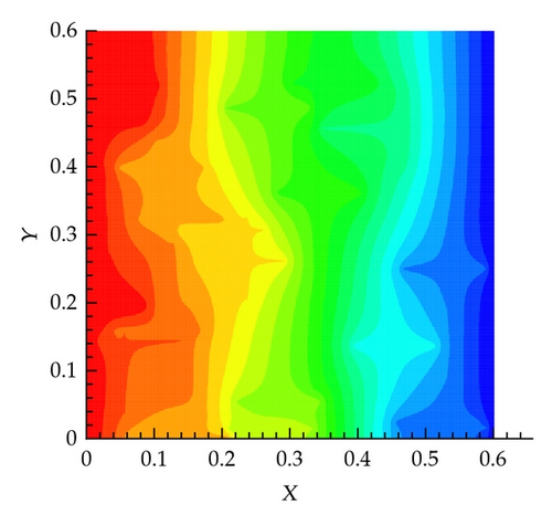
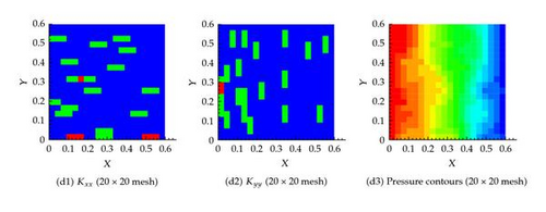
In this scenario, 20 fractures in x and 20 in the y directions are considered, as shown in Figure 9(a). The pressure field obtained by solving the governing equations based on the actual permeability field is shown in Figure 9(b). The effect of the fractures on the pressure field is apparent.
On the other hand, the effective permeability field obtained from solving the equivalent equations as explained earlier is shown in Figure 10. It is clear that as the number of grid cells increases, the system approach that based on the actual permeability field. Table 1 confirms again that the flux at the exit boundary is almost identical for the different coarsening scenarios.
6.4. Example 4: 400 Fractures in Both the Horizontal and Vertical Directions
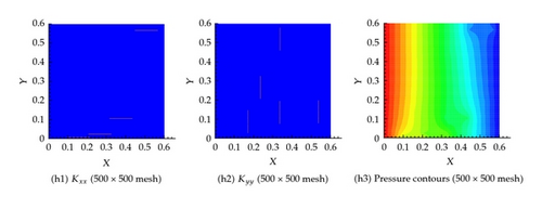
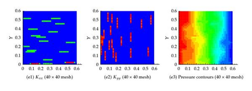
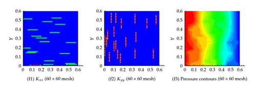
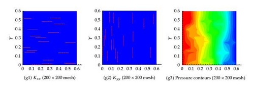
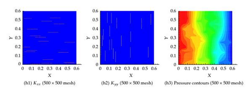
As shown in Figures 11 and 12, similar behavior is obtained for this scenario which assumes 400 fractures in both the horizontal and vertical directions for both the effective permeability and the pressure fields. In this scenario, we consider several degrees of coarsening including, 2 × 2, 10 × 10, 20 × 20, 40 × 40, 300 × 300, and 500 × 500.
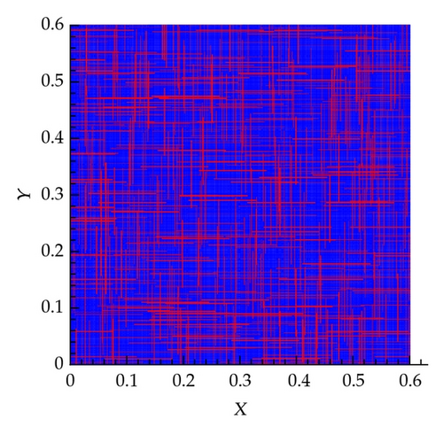
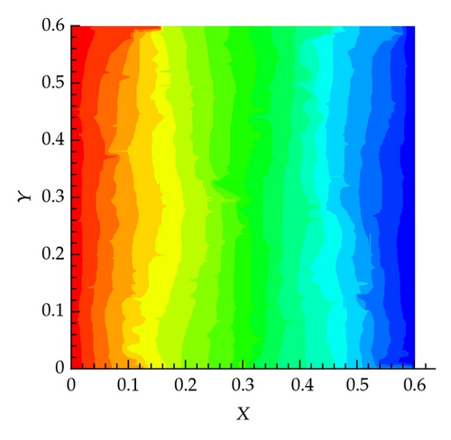
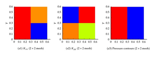
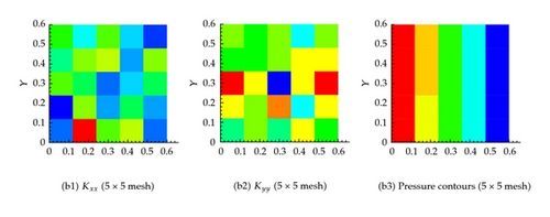
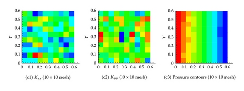
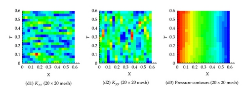
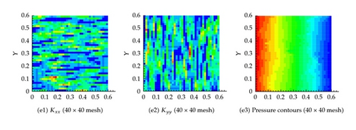
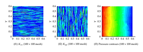
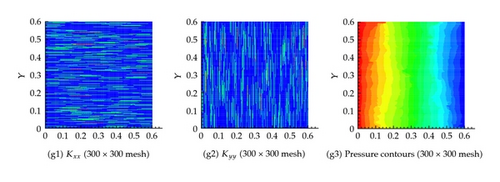
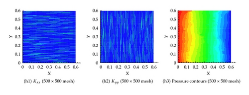
Apparently in this scenario, the large number of fractures will increase the overall effective hydraulic conductivity field which will result in a significantly larger flux compared with the other scenarios. Indeed this is the case as shown in Table 1.
7. Conclusions
In this work several numerical examples have been considered to calculate effective hydraulic properties for a given fractured porous medium domain. Several scenarios of fractured systems have been considered starting with two fractures up to 800 fractures. Cell-centered finite different method has been used, and therefore the fractures orientations are considered only in the horizontal and vertical directions. Different coarsening scenarios have been considered for each fracture scenario starting with very coarse mesh (2 × 2) all the way to the fine mesh. The fine mesh used in this work is that associated with the actual permeability field of both the matrix and the rock. Effective permeability for each cell is obtained for each coarsening scenario based on the requirement that the flux at the face of each cell is the same as that considered with the actual permeability field. It is found that the spatial distribution of effective permeability of the medium changes with the change in the degree of coarsening. That is for coarser mesh the effective permeability spans a larger domain while it reduces to the actual permeability field as the mesh approaches the fine mesh. The usefulness of this approach stems from the significantly less computational effort and memory requirement that would be required when using the upscaled permeability field and in the same time the satisfaction of conservation laws at the new scale.
Acknowledgment
The work is funded by KAUST’s GRP-CF (Global Research Partnership Collaborative Fellows) Program, and KAUST-UTAustin AEA project (7000000058).


