Viscoelastic Flow through an Axisymmetric Contraction Using the Grid-by-Grid Inversion Method
Abstract
The newly developed algorithm called the grid-by-grid inversion method is a very convenient method for converting an existing computer code for Newtonian flow simulations to that for viscoelastic flow simulations. In this method, the hyperbolic constitutive equation is split such that the term for the convective transport of stress tensor is treated as a source which is updated iteratively. This allows the stress tensors at each grid point to be expressed in terms of velocity gradient tensor at the same location, and the set of stress tensor components is found after inverting a small matrix at each grid point. To corroborate the robustness and accuracy of the grid-by-grid inversion method, we apply it to the 4 : 1 axisymmetric contraction problem. This algorithm is found to be robust and yields accurate results as compared with other finite volume methods. Any commercial CFD packages for Newtonian flow simulations can be easily converted to those for viscoelastic fluids exploiting the grid-by-grid inversion method.
1. Introduction
Contrary to the techniques of computational fluid dynamics for Newtonian fluids, the numerical algorithms for viscoelastic flows are not so matured. The hyperbolic nature of the constitutive equation incurs peculiar flow phenomena such as rod-climbing and extrudate swell as well as causes difficulties in numerical simulation [1–3]. Since the momentum balance equation is elliptic in steady state and parabolic in unsteady state, the complete set for viscoelastic flows is a mixed type, hyperbolic-elliptic, or hyperbolic-parabolic. This situation is difficult to treat numerically since it is difficult to devise a numerical algorithm that works for mixed systems. Another difficulty associated with the hyperbolic constitutive equation is the choice of appropriate boundary conditions for the stress field at the boundary of computational domain. One can impose nonslip boundary condition on the walls for the velocity field but there exist no apparent or natural boundary conditions for the stress components at the wall. Various numerical techniques for solving viscoelastic flows, such as finite volume methods, finite element methods, and spectral methods, are well documented in the references cited [4–9].
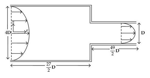
In the present investigation, a newly developed algorithm called the grid-by-grid inversion method [10] is employed to solve the viscoelastic flows through an axisymmetric contraction. Figure 1 shows the flow geometry for the axisymmetric contraction. Viscoelastic fluid passes from one circular tube into the other tube of smaller radius and generates a complex flow having a strong shear near the walls and uniaxial extension along the centerline. The existence of strong shearing zones and uniaxial extension zone makes this flow geometry a good test bed for numerical algorithms of viscoelastic fluids. Many investigators of rheology adopt this flow geometry as an important benchmark problem, especially the 4 : 1 contraction geometry [11]. We shall solve the 4 : 1 axisymmetric contraction problem employing the newly developed “grid-by-grid inversion method” [10], which is implemented based on a finite volume method [10].
The hyperbolic constitutive equations of viscoelastic fluids have a nonlocal character because of the term representing convective transport of stress tensor. If this term is assumed to be known, the constitutive equation becomes local and the stress tensor is easily evaluated for a given velocity gradient tensor at the same location. The six stress tensor components for the cases of a three-dimensional flow are found after inverting a six by six matrix at each grid point and are substituted into the Navier-Stokes equation as a source term. In this way, the numerical solution of viscoelastic flows becomes as straightforward as that of Newtonian fluids. We call this algorithm the grid-by-grid inversion method since the viscoelastic stress tensor is obtained by the grid-by-grid inversion of a matrix equation at each grid point. This algorithm can easily be implemented using finite volume methods, finite element methods and spectral methods. When applied to the 4 : 1 axisymmetric contraction problem, it is found that the grid-by-grid inversion method yields accurate results efficiently in comparison with numerical results of traditional algorithms.
2. Governing Equations and the Grid-by-Grid Inversion Method
- (1)
vn and τn have obtained in the previous time step n.
- (2)
Assume vn+1(it) and τn+1(it). For the first iteration (it = 1), vn+1(it)=vn and τn+1(it)=τn.
- (4)
Using vn+1(it), solve (2.7) (β ≠ 0) or (2.16) (β = 0) for τn+1(it+1) by inverting a six-by-six matrix at each grid point including the boundary grids.
- (5)
Using τn+1(it+1),
(β ≠ 0) solve the momentum equation, (2.9), and continuity equation to find vn+1(it+1).
- (6)
Convergence check for τn+1 and vn+1. If not converged, go to step (2). Otherwise, update the time step and go to step (1).
Usually convergence is attained in two or three iterations. The novelty of the grid-by-grid inversion method is its easiness of numerical implementation. As noted in the above procedure, one can easily convert any existing computer code for Newtonian flow simulations to that for viscoelastic flow simulation by adding a subroutine that solves the viscoelastic constitutive equation using the grid-by-grid inversion method, summarized as steps (3)~(4), to evaluate the viscoelastic source terms in the Navier-Stokes equation, ∇·τ. Adding a source term to the Navier-Stokes equation is an easy procedure whether we employ a finite volume method or a finite element method. In the subroutine for the viscoelastic constitutive equation, one inverts a small matrix at each grid point, which can be performed cheaply. Therefore, one can easily convert any commercial CFD package for Newtonian fluid flows to that for viscoelastic fluids employing the grid-by-grid inversion method. Its robustness and accuracy are corroborated in the next section, where the grid-by-grid inversion method is employed to solve the 4 : 1 viscoelastic axisymmetric contraction problem. Although Phillips and Williams [16] solve the viscoelastic constitutive equation by converting small matrix equations in their semi-Lagrange method, it is very difficult to convert an existing Newtonian code to a viscoelastic code using the semi-Lagrange method since it treats the momentum and the constitutive equation simultaneously.
3. Viscoelastic Flow through an Axisymmetric Contraction
4. Results
- (-)
inlet velocity
We have employed three sets of grid system to ensure grid convergence of numerical results. For the three sets of grids, that is, 14,580 (Grid A), 32,535 (Grid B), and 57,960 (Grid C), the extrastress component τzz is plotted when λ = 1.0 for Re = 0.0 along r = 1 in Figure 2(a), and along r = 0.064 in Figure 2(b). For there three mesh systems, the numbers of cells along r in the small tube are 30, 45, and 60, respectively. For Grid A, the minimum Δr is 0.005 at the wall and it grows gradually until it becomes 5.1 × 10⁻² at the center. For Grid B, (Δr) min is 0.003 and (Δr) max is 3.4 × 10⁻² at the center, and for Grid C, (Δr) min = 0.002 at the wall and (Δr) max = 2.3 × 10⁻² at the center. The results of the present work are also compared with those of Phillips and Williams [11]. Though the grid number increases from 32,535 to 57,960, there is not appreciable change in τzz. Therefore, we adopt Grid B in the subsequent computations. Figure 3 shows the extrastress component τzz at Re = 0.0 for λ = 0.5,1.0, and 1.5 along r = 1.0 (Figure 2(a)) and along r = 0.064 (Figure 2(b)). The grid-converged data for τzz obtained from the grid-by-grid inversion method are somewhat smaller than the benchmark data of Phillips and Williams [11]. At the corner of the contractor, τzz has a sharp overshoot, which increases with respect to λ, and it settles down to a downstream value rapidly. Near the center of the contracted channel (r = 0.064), a smaller overshoot of τzz appears, which increases as λ increases, and it settles down to a downstream value much slowly as compared to that at the wall (r = 1.0).
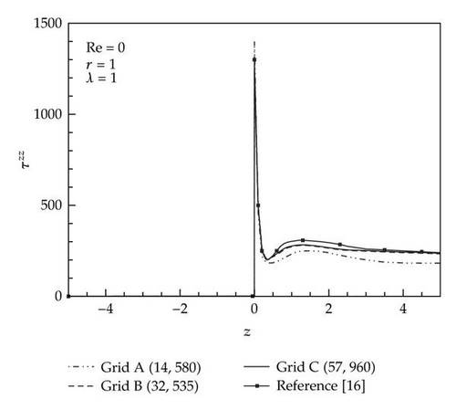
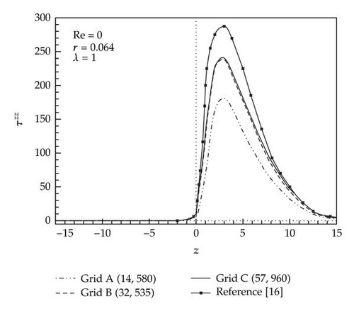
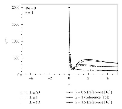
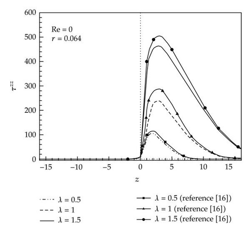
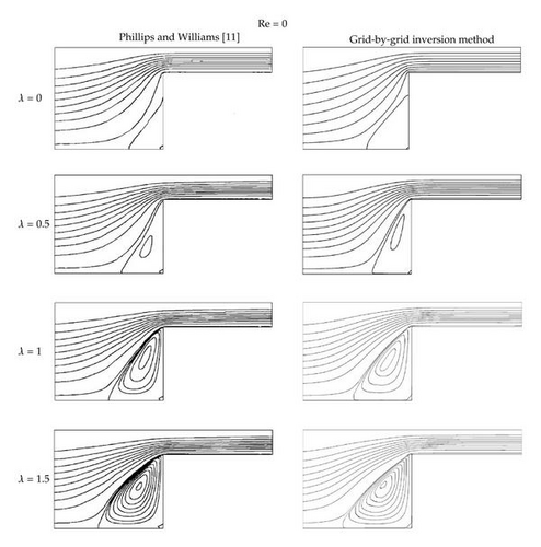
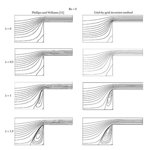
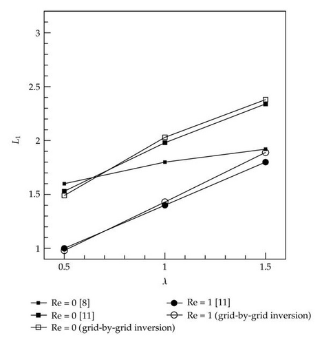
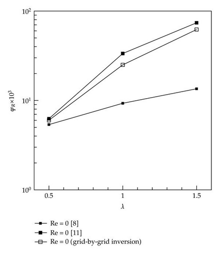
Figure 4 shows comparison of streamlines for λ = 0.0, 0.5, 1.0, and 1.5 obtained from the grid-by-grid inversion method with those from the Phillips and Williams [11] when Re = 0.0. The grid-by-grid inversion method yields accurate results as compared with the benchmark data for the range of λ values considered. The size of the corner vortex increases as λ increases. Figure 5 depicts comparison of streamlines at various values of λ when Re = 1.0. The predictions of the grid-by-grid inversion method are also in good agreement with those of the benchmark data [11]. Comparing with the streamlines of Re = 0.0, it is found that the vortex sizes are diminished due to the inertia effect [11]. The size of the corner vortex can be measured using a parameter L1, as suggested by Phillips and Williams [11] and Oliveira et al.[8], which is the distance of the upstream separation point from the salient corner. Figure 6 shows the variation of L1 with respect to λ for Re = 0.0 and Re = 1.0. For Re = 1.0, the grid-by-grid inversion method is found to yield results similar to those of the benchmark data of Phillips and Williams [11]. For Re = 0.0, the results of the grid-by-grid inversion method are compared with those of Oliveira et al. [8] as well as those of Phillips and Williams [11]. It is shown that both the grid-by-grid inversion and Phillips and Williams [11] yield L1 somewhat larger than those of Oliveira et al. [8]. Since Oliveira et al. [8] do not consider the case Re = 1.0, we cannot compare the grid-by-grid inversion method with Oliveira et al. when Re = 1.0. To corroborate the accuracy of the grid-by-grid inversion method further, we compare the results for the vortex intensity ΨR, which is defined as the flow rate in recirculation divided by inlet flow rate, in Figure 7 when Re = 0.0. As in previous comparison, the grid-by-grid inversion method yields results similar to those of Phillips and Williams [11], while Oliveira et al. [8] predicts results somewhat smaller than the grid-by-grid inversion method. The grid-by-grid inversion method yields results for λ larger than 1.5 and Re larger than 1.0, which demonstrates the robustness of the grid-by-grid inversion method as compared to other finite volume methods or finite element methods [9, 11, 16, 18].
5. Conclusion
The grid-by-grid inversion method [10] has been applied to the 4 : 1 circular contraction problem in the present investigation. Viscoelastic flows through the contraction generate complex flows exhibiting strong shear and uniaxial extension, which is a good test bed for the robustness and accuracy of a new numerical algorithms. In the grid-by-grid inversion method [10], the hyperbolic constitutive equation is split such that the term for the convective transport of stress tensor is treated as a source, which is updated iteratively. This allows the stress tensor at each grid point to be expressed in terms of velocity gradient tensor at the same location, and the set of stress tensor components is found after inverting a small matrix at each grid point. The grid-by-grid inversion method can be implemented easily in any commercial CFD packages for Newtonian fluid flows to convert them to be used for viscoelastic fluid flows. The grid-by-grid inversion method is found to yield accurate results as compared with the benchmark data of Phillips and Williams [11]. It predicts accurately the variation of corner vortex size and the τzz overshoot with respect to λ at Re = 0.0 and Re = 1.0.
Acknowledgment
This paper was supported by the Human Resources Development of the Korea Institute of Energy Technology Evaluation and Planning (KETEP) Grant funded by the Korea Government Ministry of Knowledge and Economy (no. 20114010203090).


