Exact Solutions of Nonlinear Equation of Rod Deflections Involving the Lauricella Hypergeometric Functions
Abstract
The stress induced in a loaded beam will not exceed some threshold, but also its maximum deflection, as for all the elastic systems, will be controlled. Nevertheless, the linear beam theory fails to describe the large deflections; highly flexible linear elements, namely, rods, typically found in aerospace or oil applications, may experience large displacements—but small strains, for not leaving the field of linear elasticity—so that geometric nonlinearities become significant. In this article, we provide analytical solutions to large deflections problem of a straight, cantilevered rod under different coplanar loadings. Our researches are led by means of the elliptic integrals, but the main achievement concerns the Lauricella hypergeometric functions use for solving elasticity problems. Each of our analytic solutions has been individually validated by comparison with other tools, so that it can be used in turn as a benchmark, that is, for testing other methods based on the finite elements approximation.
1. Introduction
1.1. A Literature′s Overview
-
A rod is something of a hybrid, that is, a mathematical curve made up of material points. It has no cross section, yet it has stiffness. It can weigh nothing or it can be heavy. We can twist it, bend it, stretch it and shake it, but we cannot break it, it is completely elastic. Of course, it is a mathematical object, and does not exist in the physical world; yet it finds wide application in structural (and biological) mechanics: columns, struts, cables, thread, and DNA have all been modeled with rod theory.
-
A rod which offers no resistance to bending is called a string: it is completely flexible. The string model finds applications in the study of long slender structural members such as cables, where an external load dominates the mechanics and the rods flexural stiffness is negligible.
The link between elliptic functions and elastica was always understood so close, to induce the elliptic functions to be plotted through suitable curved rubber rods (G. Greenhill: Graphical representation of the elliptic functions by means of a bent elastic beam, 1876), while the paper [8] is founded on the use of the Weierstrass ℘ function. For recent developments, see: [8–15]. Inextensibility and circular shape of undeformed rod are (numerically) analyzed in [16, 17] where the load is a uniform centrally directed force.
-
The exact governing equations for the finite displacement rod theory become highly nonlinear, and, hence, it is very difficult to solve these equations analytically. Thus, for practical purposes, problems of this kind are usually solved by the methods based on the finite elements approximations. However, the closed form solutions for these problems are still important to the practical point that the accuracy of the approximate methods can be precisely evaluated by these solutions, to say nothing of the mathematical importance.
1.2. Aim of the Paper
-
When developing finite element methods, there is also a need for checking the results against an exact solution. In the case of finite element methods for geometrically nonlinear beam, frame and shell structures, elliptic integral solutions of large deflection beam and frame problems offer such exact solution.
Nevertheless, his approach is a bit obsolete nowadays because he computes the elliptic integrals numerically through the arithmetic-geometrical means.
We are going to analyze an elastic, thin, flexible rod, clamped at one end (cantilever) bent under different loadings whose plane coincides with that of the strained centerline. Equating the exact curvature in cartesian coordinates to the bending moment divided into the flexural rigidity, one is led to a second-order nonlinear and nonautonomous differential equation. Boundary conditions are given both on the clamped end (Cauchy problem), so that, for example, if the constraint is perfect, displacement and rotation have to be zero there. We discarded the illusion of a general system of loads and rods and restricted ourselves to only one configuration, charged by a single load and treating each single problem by means of the special functions of mathematical physics. The chosen loads are constant couple, evenly distributed load, shear at the tip, hydrostatic load, and sinusoidal load. All our force loads have to be understood as “dead load”, namely, always equal to itself and then not “follower” as are currently named the loads keeping a fixed inclination to the rod before and after the strain.
For one of the above loads, based on the rod′s unextensibility, we computed in closed form the Ω free tip coordinates, parametrized to the load itself. We use everywhere nondimensional quantities; the reader will see how advantageous is such a choice in producing “universal” relationships which (in elliptical and/or hypergeometric cloth) keep their formal validity in several situations.
1.3. Special Functions Tools
We assume that the reader knows the elliptic functions (see [25] for details), but let us recall hereinafter the less known Lauricella hypergeometric ones.
2. Bent Slender Rod: A Large Deflections 2D-Model
- (A1)
the rod is thin, initially straight, homogeneous, with uniform cross-section and uniform flexural stiffness EJ, where E is the Young modulus, and J the cross-section moment of inertia about a “neutral” axis normal to the plane of bending and passing through the central line;
- (A2)
the slender rod is charged by coplanar dead loads;
- (A3)
linear constitutive load: the induced curvature is proportional via 1/(EJ) to the bending moment. The rod undergoes large deflections but small strains;
- (A4)
the shear transverse deformation is ignored, and the rod is assumed to keep constant its previous length (inextensibility);
- (A5)
a stationary strain field, by isostatic equilibrium of active loads and reactive forces, takes place, and, due to rest of static equilibrium, no rod element undergoes acceleration.
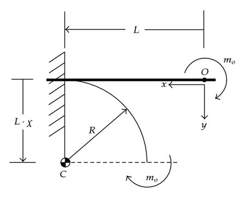
2.1. Rod Inflected by a Constant Bending Couple at Its Tip
2.2. The Horizontal Heavy Rod
-
This problem… has shown considerable resistance to a closed form solution and all investigations dealing with it have employed approximate methods only.
Accordingly, he obtains elastica coordinates as parametric functions of the arclength s, stopping their Maclaurin expansions to s10.
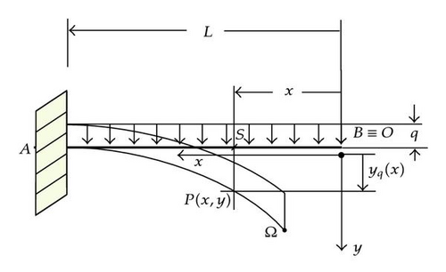
Formula (2.15), founded on the Lauricella hypergeometric functions, provides a very compact explicit solution to the elastica of a thin clamped heavy rod. We cannot give now the due importance to (2.15) due to the lack of software packages whose quickness and precision of computing are comparable to those available on Mathematica for the Gauss or Appell hypergeometric functions. We did invite Wolfram to consider such a necessity, but no forecasting is possible. As far as we are concerned, the integral (2.14) cannot be led to any other known special functions or to any combination of them.
2.3. A Tip-Sheared Horizontal Rod
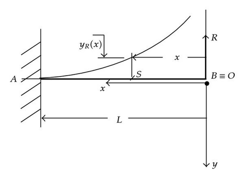
From it, one could obtain the relevant contour plots cutting by planes of μ = constant. The thing is shown in Figure 5, where the clamped end is on the left. The deflection curves are given for some values of μ : 0.2; 0.4; 0.6; 0.8. Each of them is compared with the dot curve coming from the approximate theory6. Mind that ξ is ranged as ξΩ < ξ < 1, and ξΩ has to be found from (3.12). Accordingly, each single μ-curve has been plotted between ξ = 1 and ξΩ(μ). From the physical viewpoint, the lines′7 comparison shows at the low loads an agreement which is becoming worst for increasing loads when the approximate theory is progressively failing.
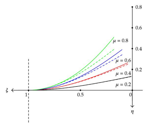
Going again to formula (2.25), his peculiarities are: it is nondimensional; it is new, in closed form, exact, and explicit. Moreover, for being implemented, no previous transcendental equation has to be solved; it requires only to compute the dimensionless parameter μ = (RL2)/(2EJ) holding all the rod physical data.
-
The modulus of elliptic functions k and the parameter F1 play the role of integration constants and they are related to the force P and the angle φ0 by boundary conditions for each case of rod bending.
In fact, they do not provide the k computation at all, marking their plot solutions not in terms of P (as it should be done), but of a sequence of k values 0.5; 0.6; 0.85; 1 − 10−5 see Figure 2, page 742 of [33], so that their (x, y) solution seems to be not easily accessible from P.
2.4. The Rod Inflected by Hydrostatic Pressure
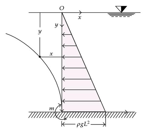
2.5. The Rod Loaded by a Sinusoidal Bending Moment
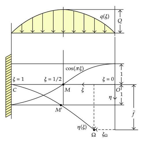
Assumption A3 implies that our systems are ruled by differential equations affected by a geometrical nonlinearity due to the nonlinear link between the curvature ϰ and yx. But ϰ, which is the consequence on the rod, is linked to its cause, namely, the bending moment M, by a Linear Constitutive Law ϰ = ±M/EJ, being EJ the flexural stiffness. Such a linearity implies that, by superposition, whenever some moment distribution is repeated periodically, we can make its Fourier expansion, so that the rod bending moment is broken out into the addition of an infinitely many harmonics sine/cosine. In such a way, one will get the elastica by superposition, of course retaining those harmonics deemed useful or necessary.
3. How to Compute the Tip Position after the Strain
Considering the small deflections, the deformed centerline′s curvature is approximately equated to the deflection′s second derivative, assuming the rod deformation field to proceed along purely vertical displacements. If it is so, the free end O(ξ = 0, η = 0) will be mapped to ξ = 0, with η(0) ≠ 0, but having the elastica as horizontal projection, its full unstrained length, then the rod will undergo extension.
With large displacements all, this is not true any more, and a further unknown will appear, namely, the abscissa ξΩ of the new position Ω, where O has been mapped to. Rod′s behavior under strain can be modeled in several ways. For instance in [9] after integrating the elastica, the authors write five congruence relationships involving geometric quantities before and after the strain and then leave the rod free of extension.
Following a completely different method, in [34] some possible alternatives like rotational load, load always perpendicular to the tangent at the tip and so on, are taken into account.
Lemma 3.1. Consider the transcendental x-equation where a > b ≥ x > y ≥ c
Proof. Let a > b ≥ x > y ≥ c. Observe that the function

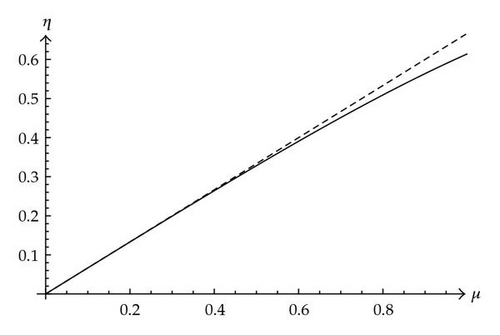
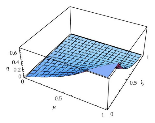
First, the (3.12) relationship is plotted as shown in Figure 9.
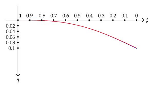
Plugging (3.12) in (2.25), we obtain for the tip η as a function of μ alone. But such a formula is too long, and then we will omit here, providing its relevant plot.
4. Conclusions
Five elasticae have been analytically solved of a thin cantilever rod bent by different coplanar “dead” loadings12, namely, whose direction remains unchanged during the deformation of the rod. They are concentrated couple, tip shear, evenly continuous load, hydrostatic load, and sinusoidal load. Each of them describes a single physical situation for which we obtain the large deflections in closed form through elliptic and/or hypergeometric functions. Some care has been put (tip sheared rod) in providing analytically, via the isometric assumption, the free end position after the strain, parametrizing its coordinates as a function of the load. Some of our solutions, specially that to the heavy rod by the Lauricella functions, have enriched the literature on the elastica.
Acknowledgments
The authors are indebted to their friend Aldo Scimone who drew some Figures of this paper; they hereby take opportunity for thanking him warmly. They wish also to thank the anonymous referee whose valuable criticism improved their article.
Endnotes
- 1.
A space tether is a long cable used to connect spacecraft to other orbiting bodies such as space stations, boosters, payload, and so forth in order to transfer energy and momentum.
- 2.
The problem of 3D-elastica is very old, but out of our purpose. We will say only that it first appeared in Lagrange′s Mécanique Analytique 2nd edition (1811). J. Binet (Mémoire sur l′intégration des équations de la courbe élastique à double courbure, 1844) and M. Wantzel (Note sur l′intégration des équations de la courbe élastique à double courbure, 1844) arrived at the same differential system, vaguely formulated, and not affronted. A modern treatment of a particular case can be read in [35], with its specific bibliography.
- 3.
We quote three works: (a) De progressionibus transcendentibus, Op. omnia, S.1, vol. 28; (b) De curva hypergeometrica Op. omnia, S.1, vol. 16; (c) Institutiones Calculi integralis, 1769, vol. II.
- 4.
A.M. Legendre, Exercices de calcul intégral, II, quatriéme part, sect. 2, Paris 1811.
- 5.
In [36] putting R = 2/a, he gets the elastica y(x) through the integral
(4.1)“Die Kurve welche diese Gleichung entspricht, heißt die elastische Linie weil ein elastischer Stab der an dem Ende befestigt und an dem andern Ende belastet ist, diese Form annimmt.” - 6.
Under transversal load at the cantilever tip, this problem in strength of materials is solved in cartesian coordinates following the linear approximation; the solution is found (e.g., see [37, page 305]) to be
(4.2)in dimensionless form. - 7.
Notice that the plots are coming after Mathematica′s computation of our explicit solution (2.25), but adding the map ξ → 1 − ξ in order to provide the geometrical true configuration of the stressed rod.
- 8.
Inserting in ε some numerical values, for example, L = 5 m, q = 6 N × m−1, EJ = 100 N × m2, g = 9,81 m × s−2, one gets: ε ≈ 3 × 10⁻², so that, unless of assuming unrealistic lengths, ε is essentially much less than unity.
- 9.
Only in some special cases such a tip path description is quick. For instance for a rod loaded by a fixed couple (Section 2.1), one gets ξΩ = 1 − χ, f = χ.
- 10.
Having for instance L = 1 m, R = 10 N, EJ = 100 N × m2, we get μ = RL2/2EJ = 0.05.
- 11.
Nothing to say, apart from the more strict link imposed by the transcendental inequality (linearity range), (3.12) requires μ ≤ 1.
- 12.
The contrary case is that of the follower load which is being unchanged in its relationship with the rod, for example, keeping its direction perpendicular—or inclined—to it during and after the strain.


