Free Vibration Analysis of a Rotating Composite Shaft Using the p-Version of the Finite Element Method
Abstract
This paper is concerned with the dynamic behavior of the rotating composite shaft on rigid bearings. A p-version, hierarchical finite element is employed to define the model. A theoretical study allows the establishment of the kinetic energy and the strain energy of the shaft, necessary to the result of the equations of motion. In this model the transverse shear deformation, rotary inertia and gyroscopic effects, as well as the coupling effect due to the lamination of composite layers have been incorporated. A hierarchical beam finite element with six degrees of freedom per node is developed and used to find the natural frequencies of a rotating composite shaft. A program is elaborate for the calculation of the eigenfrequencies and critical speeds of a rotating composite shaft. To verify the present model, the critical speeds of composite shaft systems are compared with those available in the literature. The efficiency and accuracy of the methods employed are discussed.
1. Introduction
The application of composite shafts has come a long way from early low-speed automotive driveshafts to helicopter tail rotors operating above the second critical speed. With operation at supercritical speeds, a substantial amount of payoffs and net system weight reductions are possible. At the same time, the rotordynamic aspects assume more importance, and detailed analysis is required. There are some technological problems associated with implementation, such as joints with bearings, affixing of lumped masses, couplings, provision of external damping, and so forth. The solutions proposed are just adequate, but require substantial refinements, which might explain some of the differing experiences of various authors.
Zinberg and Symonds [1] described a boron/epoxy composite tail rotor driveshaft for a helicopter. The critical speeds were determined using equivalent modulus beam theory (EMBT), assuming the shaft to be a thin-walled circular tube simply supported at the ends. Shear deformation was not taken into account. The shaft critical speed was determined by extrapolation of the unbalance response curve which was obtained in the subcritical region.
Dos Reis et al. [2] published analytical investigations on thin-walled layered composite cylindrical tubes. In part III of the series of publications, the beam element was extended to formulate the problem of a rotor supported on general eight coefficient bearings. Results were obtained for shaft configuration of Zinberg and Symmonds. The authors have shown that bending-stretching coupling and shear-normal coupling effects change with stacking sequence, and alter the frequency values. Gupta and Singh [3] studied the effect of shear-normal coupling on rotor natural frequencies and modal damping. Kim and Bert [4] have formulated the problem of determination of critical speeds of a composite shaft including the effects of bending-twisting coupling. The shaft was modelled as a Bresse-Timoshenko beam. The shaft gyroscopics have also been included. The results compare well with Zinberg′s rotor [1]. In another study, Bert and Kim [5] have analysed the dynamic instability of a composite drive shaft subjected to fluctuating torque and/or rotational speed by using various thin shell theories. The rotational effects include centrifugal and Coriolis forces. Dynamic instability regions for a long span simply supported shaft are presented.
M.-Y. Chang et al. [6] published the vibration behaviours of the rotating composite shafts. In the model, the transverse shear deformation, rotary inertia, and gyroscopic effects, as well as the coupling effect due to the lamination of composite layers have been incorporated. The model based on a first-order shear deformable beam theory (continuum-based Timoshenko beam theory).
C.-Y. Chang et al. [7] published the vibration analysis of rotating composite shafts containing randomly oriented reinforcements. The Mori-Tanaka mean-field theory is adopted here to account for the interaction at the finite concentrations of reinforcements in the composite material.
Additional recent work on composite shafts dealing with both the theoretical and experimental aspects was reported by Singh [8], Gupta and Singh [3], and Singh and Gupta [9, 10]. Rotordynamic formulation based on equivalent modulus beam theory was developed for a composite rotor with a number of lumped masses and supported on general eight coefficient bearings. A layerwise beam theory was derived by Gupta and Singh [3] from an available shell theory, with a layerwise displacement field, and was then extended to solve a general composite rotordynamic problem. The conventional rotor dynamic parameters as well as critical speeds, natural frequencies, damping factors, unbalance response, and threshold of stability were analysed in detail and results from the formulations based on the two theories, namely, the equivalent modulus beam theory (EMBT) and layerwise beam theory (LBT) were compared [9, 10]. The experimental rotordynamic studies carried by Singh and Gupta [11, 12] were conducted on two filament wound carbon/epoxy shafts with constant winding angles (±45° and ±60°). Progressive balancing had to be carried out to enable the shaft to traverse through the first critical speed. Inspite of the very different shaft configurations used, the authors′ have shown that bending-stretching coupling and shear-normal coupling effects change with stacking sequence, and alter the frequency values.
Some practical aspects such as effect of shaft disc angular misalignment, interaction between shaft bow, which is common in composite shafts and rotor unbalance, and an unsuccessful operation of a composite rotor with an external damper were discussed and reported by Singh and Gupta [11]. The Bode and cascade plots were generated and orbital analysis at various operating speeds was performed. The experimental critical speeds showed good correlation with the theoretical prediction.
This paper deals with the p-version, hierarchical finite element method applied to free vibration analysis of rotating composite shafts. The hierarchical concept for finite element shape functions has been investigated during the past 25 years. Babuska et al. [13] established a theoretical basis for p-elements, where the mesh keeps unchanged and the polynomial degree of the shape functions is increased; however, in the standard h-version of the finite element method the mesh is refined to achieve convergence and the polynomial degree of the shape functions remains unchanged. Since then, standard forms of the hierarchical shape functions have been represented in the literature elsewhere; see for instance [14, 15].
Meirovitch and Baruh [16] and Zhu [17] have shown that the hierarchical finite element method yields a better accuracy than the h-version for eigenvalues problems. The hierarchical shape functions used by Bardell [18] are based on integrated Legendre orthogonal polynomials; the symbolic computing is used to calculate the mass and stiffness matrices of beams and plates. Côté and Charron [19] give the selection of p-version shape functions for plate vibration analysis.
In the presented composite shaft model, the Timoshenko theory will be adopted. It is the purpose of the present work to study dynamic characteristics such as natural frequencies, whirling frequencies, and the critical speeds of the rotating composite shaft. In the model, the transverse shear deformation, rotary inertia, and gyroscopic effects, as well as the coupling effect due to the lamination of composite layers have been incorporated. To determine the rotating shaft system′s responses, the hierarchical finite element method with trigonometric shape functions [20, 21] is used here to approximate the governing equations by a system of ordinary differential equations.
2. Equations of Motion
2.1. Kinetic and Strain Energy Expressions
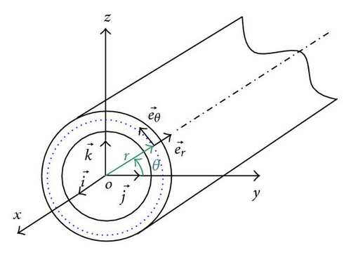
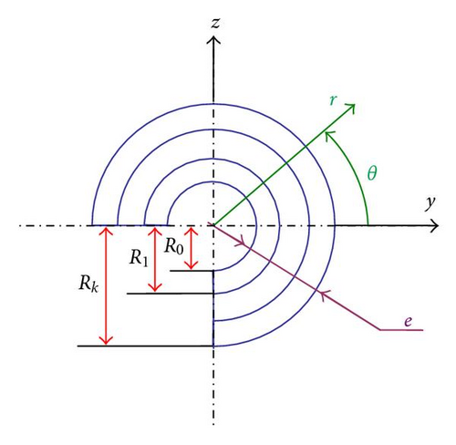
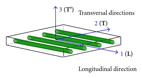
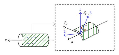
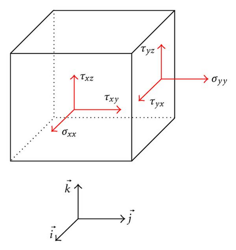
The shaft is modelled as a Timoshenko beam, that is, first-order shear deformation theory with rotary inertia and gyroscopic effect is used. The shaft rotates at constant speed about its longitudinal axis. Due to the presence of fibers oriented than axially or circumferentially, coupling is made between bending and twisting. The shaft has a uniform, circular cross-section.

2.2. Hierarchical Beam Element Formulation
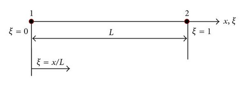
In this work,
The functions (f1, f2) are those of the finite element method necessary to describe the nodal displacements of the element, whereas the trigonometric functions fr+2 contribute only to the internal field of displacement and do not affect nodal displacements. The most attractive particularity of the trigonometric functions is that they offer great numerical stability. The shaft is modeled by only one element called hierarchical finite element.
The system obtained is linear of which equations are coupled once by the gyroscopic effect, represented by the matrix [G].
[M] and [K] are the conventional hierarchical finite element mass and stiffness matrix, [G] is the gyroscopic matrix (the different matrices of the system of equation are given in the appendix).
3. Results
A program based on the formulation proposed was developed for the resolution of (16).
3.1. Convergence
First, the material properties for boron-epoxy are listed in Table 1, and the geometric parameters are L = 2.47 m, D = 12.69 cm, e = 1.321 mm, 10 layers of equal thickness (90°, 45°, −45°, , 90°). The shear correction factor ks = 0.503 and the rotating speed Ω = 0.
| Boron-epoxy | Graphite-epoxy | |
|---|---|---|
| E11 (GPa) | 211.0 | 139.0 |
| E22 (GPa) | 24.1 | 11.0 |
| G12 (GPa) | 6.9 | 6.05 |
| G23 (GPa) | 6.9 | 3.78 |
| v12 | 0.36 | 0.313 |
| ρ (kg/m3) | 1967.0 | 1578.0 |
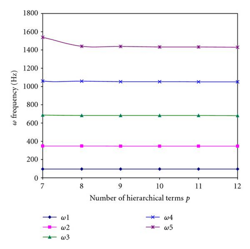
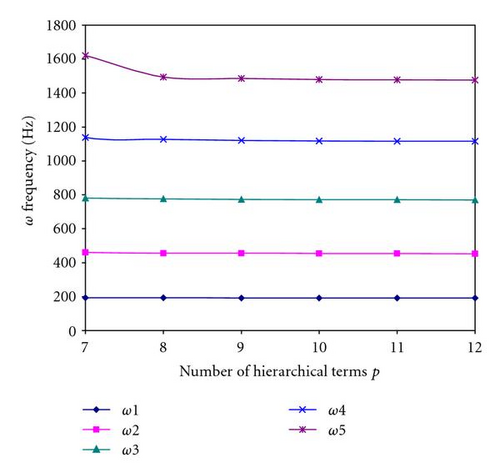
The results of the five bending modes for various boundary conditions of the composite shaft as a function of the number of hierarchical terms are shown in Figures 7 and 8. Figures clearly show that rapid convergence from above to the exact values occur as the number of hierarchical terms is increased.
3.2. Numerical Examples and Discussions
In all the following examples, p = 10.
In the first example, the properties of the boron-epoxy composite shaft are given by Table 1. The results obtained using the present model are shown in Table 2 together with those of referenced papers. As can be seen from the table, our results are close to those predicted by other beam theories. Since in the studied example the wall of the shaft is relatively thin, models based on shell theories [4] are expected to yield more accurate results. In the present example, the critical speed measured from the experiment however is still underestimated by using Sander shell theory, while overestimated by Donnell shallow shell theory. When the material of the shaft is changed to the graphite-epoxy given in Table 1 with other conditions left unchanged, the critical speed obtained from the present model is shown in Table 3. In this case, the result from the present model is compatible to that of the Bresse-Timoshenko beam theory of M.-Y. Chang et al. [6].
| L = 2.47 m, D = 12.69 cm, e = 1.321 mm, 10 layers of equal thickness (90°, 45°, −45°, , 90°), ks = 0.503 | ||
|---|---|---|
| Theory or method | First critical | |
| speed (rpm) | ||
| Zinberg and Symonds [1] | Measured experimentally | 6000 |
| EMBT | 5780 | |
| dos Reis et al. [2] | Bernoulli-Euler beam theory with stiffness | 4942 |
| determined by shell finite elements | ||
| Kim and Bert [4] | Sanders shell theory | 5872 |
| Bert [23] | Donnell shallow shell theory | 6399 |
| Bert and Kim [22] | Bernoulli-Euler beam theory | 5919 |
| Bresse-Timoshenko beam theory | 5788 | |
| Gupta and Singh [3] | EMBT | 5747 |
| LBT | 5620 | |
| M.-Y. Chang et al. [6] | Continuum-based Timoshenko beam theory | 5762 |
| Present | Timoshenko beam theory by the p-version | 5760 |
| of the finite element method | ||
| L = 2.47 m, D = 12.69 cm, e = 1.321 mm, 10 layers of equal thickness (90°, 45°, −45°, , 90°), ks = 0.503 | ||
|---|---|---|
| Theory or method | First critical | |
| speed (rpm) | ||
| Bert and Kim [22] | Sanders shell theory | 5349 |
| Donnell shallow shell theory | 5805 | |
| Bernoulli-Euler beam theory | 5302 | |
| Bresse-Timoshenko beam theory | 5113 | |
| M.-Y. Chang et al. [6] | Continuum-based Timoshenko beam theory | 5197 |
| Present | Timoshenko beam theory by the p-version | 5200 |
| of the finite element method | ||
Next, comparisons are made with those of [6, 22] for different length to mean diameter ratios L/D. The shafts being analysed are made of the graphite-epoxy material given in Table 1 and all have the same lamination [90°/45°/45°//90°]. The mean diameter and the wall thickness of the shaft remain the same as the previous examples. The shear correction factor being used is again 0.503. The results are listed in Table 4. Further results being compared are for generalized orthotropic composite tube of different lamination angles η. The results are shown in Table 5.
| Theory or method | L/D | ||||||||
|---|---|---|---|---|---|---|---|---|---|
| 2 | 5 | 10 | 15 | 20 | 25 | 30 | 35 | ||
| Sanders shell | 112400 | 41680 | 16450 | 8585 | 5183 | 3441 | 2440 | 1816 | |
| Bert and Kim [22] | Bernoulli-Euler | 329600 | 76820 | 20210 | 9072 | 5121 | 3283 | 2282 | 1677 |
| Bresse-Timoshenko | 176300 | 54830 | 17880 | 8543 | 4945 | 3209 | 2246 | 1658 | |
| M.-Y. Chang et al. [6] | Continuum-based Timoshenko | 181996 | 55706 | 17929 | 8527 | 4925 | 3192 | 2233 | 1648 |
| beam theory | |||||||||
| Present | Timoshenko beam theory by | 184667 | 56196 | 18005 | 8549 | 4934 | 3198 | 2236 | 1650 |
| the p-version of the finite | |||||||||
| element method | |||||||||
| Theory or method | Lamination angle η (°) | |||||||
|---|---|---|---|---|---|---|---|---|
| 0 | 15 | 30 | 45 | 60 | 75 | 90 | ||
| Sanders shell | 5527 | 4365 | 3308 | 2386 | 2120 | 2020 | 1997 | |
| Bert and Kim [22] | Bernoulli-Euler | 6425 | 5393 | 4269 | 3171 | 2292 | 1885 | 1813 |
| Bresse-Timoshenko | 6072 | 5209 | 4197 | 3143 | 2278 | 1874 | 1803 | |
| M.-Y. Chang et al. [6] | Continuum-based Timoshenko | 6072 | 5331 | 4206 | 3124 | 2284 | 1890 | 1816 |
| beam theory | ||||||||
| Timoshenko beam theory by the | 6094 | 5359 | 4222 | 3129 | 2284 | 1890 | 1816 | |
| Present | p-version of the finite element | |||||||
| method | ||||||||
In our work, the shaft is modelled by only one element with two nodes, but in the model of [6] the shaft is modelled by 20 finite elements of equal length (h-version). The rapid convergence while taking only one element and a reduced number of shape functions shows the advantage of the method used.
From the thin-walled shaft systems studied above, the present shaft model yields result in all cases close to those of the model of Bert and Kim [22] based on the Bresse-Timoshenko theory. One should stress here that the present model is not only applicable to the thin-walled composite shafts as studied above, but also to the thick-walled shafts as well as to the solid ones.
In the following example, the frequencies responses of a graphite-epoxy composite shaft system are analysed. The material properties are those listed in Table 1. The lamination scheme of the shaft remains the same as previous examples, while its geometric properties, the Campbell diagram containing the frequencies of the first five pairs of bending whirling modes of the above composite system is shown in Figure 9. The intersection point of the line (Ω = ω) with the whirling frequency curves indicate the speed at which the shaft will vibrate violently (i.e., the critical speed). The first 10 eigenvalues correspond to 5 forward (F) and 5 backward (B) whirling bending modes of the shaft.
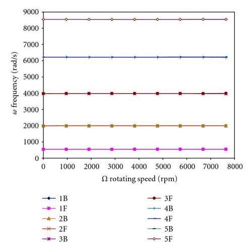
The gyroscopic effect causes a coupling of orthogonal displacements to the axis of rotation, and by consequence separates the frequencies in two branches: backward precession mode and forward precession mode. In all cases, the backward modes increase with increasing rotating speed however the forward modes decrease.
Figure 10 shows the variation of the bending fundamental frequency ω as a function of the rotating speed Ω (Campbell diagram) for different boundary conditions and different rotating speeds.
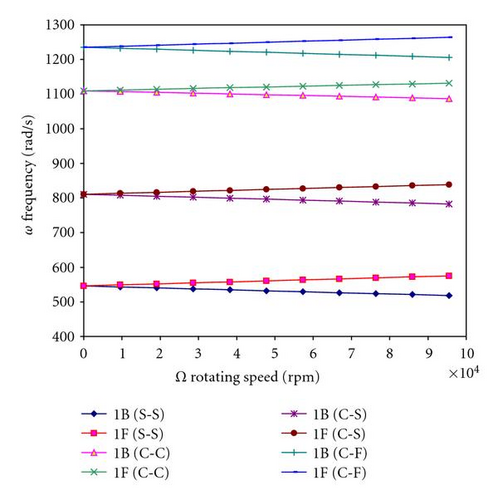
The gyroscopic effect inherent to rotating structures induces a precession motion. The backward precession modes (1B) increase with increasing the rotating speed, however the forward precession (1F) modes decrease.
4. Conclusion
- (1)
Monotonic and uniform convergence is found to occur as the number of hierarchical functions is increased.
- (2)
The dynamic characteristics of rotating composite shaft are influenced significantly by varying the fiber orientation, the rotating speed, and boundary conditions.
- (3)
The gyroscopic effect causes a coupling of orthogonal displacements to the axis of rotation, and by consequence separates the frequencies in two branches: backward and forward precession modes. In all cases, the backward modes increase with increasing rotating speed however the forward modes decrease.
Nomenclature
-
- U(x, y, z):
-
- Displacement in x direction
-
- V(x, y, z):
-
- Displacement in y direction
-
- W(x, y, z):
-
- Displacement in z direction
-
- βx:
-
- Rotation angles of the cross-section on y axis
-
- βy:
-
- Rotation angles of the cross-section on z axis
-
- ϕ:
-
- Angular displacement of the cross-section due to the torsion deformation of the shaft
-
- (x, y, z):
-
- Cartesian coordinates
-
-
- Axes of the Cartesian coordinates
-
- (x, r, θ):
-
- Cylindrical coordinates
-
-
- Axes of the cylindrical coordinates
-
- (1, 2, 3):
-
- Principal axes of a layer of laminate
-
- :
-
- Elastic constants
-
- E:
-
- Young modulus
-
- G:
-
- Shear modulus
-
- v:
-
- Poisson coefficient
-
- ρ:
-
- Masse density
-
- ks:
-
- Shear correction factor
-
- L:
-
- Length of the shaft
-
- D:
-
- Mean radius of the shaft
-
- e:
-
- Wall thickness of the shaft
-
- k:
-
- Number of the layer of the composite shaft
-
- Rn−1:
-
- The nth layer inner radius of the composite shaft
-
- Rn:
-
- The nth layer outer radius of the composite shaft
-
- R0:
-
- Inner radius of the composite shaft
-
- Rk:
-
- Outer radius of the composite shaft
-
- η:
-
- Lamination angle
-
- θ:
-
- Circumferential coordinate
-
- ξ:
-
- Local and nondimensional coordinates
-
- εij:
-
- Strain tensor
-
- σij:
-
- Stress tensor
-
- ω:
-
- Frequency, eigenvalue
-
- Ω:
-
- Rotating speed
-
- f(ξ):
-
- Shape functions
-
- [N]:
-
- Matrix of the shape functions
-
- p:
-
- Number of the shape functions or number of hierarchical terms
-
- t:
-
- Time
-
- Ec:
-
- Kinetic energy
-
- Ed:
-
- Strain energy
-
- {qi}:
-
- Generalised coordinates, with (i = U, V, W, βx, βy, ϕ)
-
- [M]:
-
- Masse matrix
-
- [K]:
-
- Stiffness matrix
-
- [G]:
-
- Gyroscopic matrix.
Appendix
The terms of the matrices are a function of the integrals, (m, n) indicate the number of the shape functions used, where (α, β) is the order of derivation.


