Peristaltic Flow of a Magneto-Micropolar Fluid: Effect of Induced Magnetic Field
Abstract
We carry out the effect of the induced magnetic field on peristaltic transport of an incompressible conducting micropolar fluid in a symmetric channel. The flow analysis has been developed for low Reynolds number and long wavelength approximation. Exact solutions have been established for the axial velocity, microrotation component, stream function, magnetic-force function, axial-induced magnetic field, and current distribution across the channel. Expressions for the shear stresses are also obtained. The effects of pertinent parameters on the pressure rise per wavelength are investigated by means of numerical integrations, also we study the effect of these parameters on the axial pressure gradient, axial-induced magnetic field, as well as current distribution across the channel and the nonsymmetric shear stresses. The phenomena of trapping and magnetic-force lines are further discussed.
1. Introduction
It is well known that many physiological fluids behave in general like suspensions of deformable or rigid particles in a Newtonian fluid. Blood, for example, is a suspension of red cells, white cells, and platelets in plasma. Another example is cervical mucus, which is a suspension of macromolecules in a water-like liquid. In view of this, some researchers have tried to account for the suspension behavior of biofluids by considering them to be non-Newtonian [1–6].
Eringen [7] introduced the concept of simple microfluids to characterise concentrated suspensions of neutrally buoyant deformable particles in a viscous fluid where the individuality of substructures affects the physical outcome of the flow. Such fluid models can be used to rheologically describe polymeric suspensions, normal human blood, and so forth, and have found applications in physiological and engineering problems [8–10]. A subclass of these microfluids is known as micropolar fluids where the fluid microelements are considered to be rigid [11, 12]. Basically, these fluids can support couple stresses and body couples and exhibit microrotational and microinertial effects.
The phenomenon of peristalsis is defined as expansion and contraction of an extensible tube in a fluid generate progressive waves which propagate along the length of the tube, mixing and transporting the fluid in the direction of wave propagation. It is an inherent property of many tubular organs of the human body. In some biomedical instruments, such as heart-lung machines, peristaltic motion is used to pump blood and other biological fluids. It plays an indispensable role in transporting many physiological fluids in the body in various situations such as urine transport from the kidney to the bladder through the ureter, transport of spermatozoa in the ductus efferentes of the male reproductive tract, movement of ovum in the fallopian tubes, vasomotion of small blood vessels, as well as mixing and transporting the contents of the gastrointestinal passage.
Peristaltic pumping mechanisms have been utilized for the transport of slurries, sensitive or corrosive fluids, sanitary fluid, noxious fluids in the nuclear industry, and many others. In some cases, the transport of fluids is possible without moving internal mechanical components as in the case with peristaltically operated microelectromechanical system devices [13].
The study of peristalsis in the context of fluid mechanics has received considerable attention in the last three decades, mainly because of its relevance to biological systems and industrial applications. Several studies have been made, especially for the peristalsis in non-Newtonian fluids which have promising applications in physiology [14–23]. The main advantage of using a micropolar fluid model to study the peristaltic flow of suspensions in comparison with other classes of non-Newtonian fluids is that it takes care of the rotation of fluid particles by means of an independent kinematic vector called the microrotation vector.
Magnetohydrodynamic (MHD) is the science which deals with the motion of a highly conducting fluids in the presence of a magnetic field. The motion of the conducting fluid across the magnetic field generates electric currents which change the magnetic field, and the action of the magnetic field on these currents gives rise to mechanical forces which modify the flow of the fluid [24]. MHD flow of a fluid in a channel with elastic, rhythmically contracting walls (peristaltic flow) is of interest in connection with certain problems of the movement of conductive physiological fluids (e.g., the blood and blood pump machines) and with the need for theoretical research on the operation of a peristaltic MHD compressor. Effect of a moving magnetic field on blood flow was studied by Stud et al. [25], Srivastava and Agrawal [26] considered the blood as an electrically conducting fluid and it constitutes a suspension of red cells in plasma. Also Agrawal and Anwaruddin [27] studied the effect of magnetic field on blood flow by taking a simple mathematical model for blood through an equally branched channel with flexible walls executing peristaltic waves using long wavelength approximation method.
Some recent studies [28–41] have considered the effect of a magnetic field on peristaltic flow of a Newtonian and non-Newtonian fluids, and in all of these studies the effect of the induced magnetic field have been neglected.
The first investigation of the effect of the induced magnetic field on peristaltic flow was studied by Vishnyakov and Pavlov [42] where they considers the peristaltic MHD flow of a conductive Newtonian fluid; they used the asymptotic narrow-band method to solve the problem and only obtained the velocity profiles in certain channel cross-sections for definite parameter values. Currently, there is only two attempts [43, 44] for a study of the effect of induced magnetic field, one for a couple-stress fluid and the other for a non-Newtonian fluid (biviscosity fluid). To the best of our knowledge, the influence of a magnetic field on peristaltic flow of a conductive micropolar fluid has not been investigate with or without the induced magnetic field.
With keeping the above discussion in mind, the goal of this investigation is to study the effect of the induced magnetic field on peristaltic flow of a micropolar fluid (as a blood model). The flow analysis is developed in a wave frame of reference moving with the velocity of the wave. The problem is first modeled and then solved analytically for the stream function, magnetic-force function, and the axial pressure gradient. The results for the pressure rise , shear stresses, the axial induced magnetic field, and the distribution of the current density across the channel have been discussed for various values of the problem parameters. Also, the contour plots for the magnetic force and stream functions are presented, the pumping characteristics and the trapping phenomena are discussed in detail. Finally, The main conclusions are summarized in the last section.
2. Mathematical Modelling
The governing equations for a magneto-micropolar fluid are as follows:
- (i)
Reynolds number Re = caρ/μ,
- (ii)
wave number δ = a/λ,
- (iii)
Strommer′s number (magnetic-force number) ,
- (iv)
the magnetic Reynolds number Rm = σμeac,
- (v)
the coupling number N = k/(k + μ) (0 ≤ N ≤ 1), m2 = a2k(2μ + k)/(γ(μ + k)) is the micropolar parameter,
- (vi)
the total pressure in the fluid, which equals the sum of the ordinary and magnetic pressure, is , and E( = −E/cH0) is the electric field strength. The parameters α, β do not appear in the governing equations as the microrotation vector is solenoidal. However, (2.12)–(2.15) reduce to the classical MHD Navier-Stokes equations as k → 0.
3. Exact Solution
In the formulation under consideration, the field strength E is the determining factor and its value can be found by integrating (2.32), which represents Ohm′s law in differential form, across the channel, taking into account the boundary conditions for ϕ and ψ in (2.30). In this case, we obtain the dimensionless E = F/h.
The shear stresses τxy and τyx are calculated at both the lower and upper walls and graphical results are shown in Figures 4–6.
4. Numerical Results and Discussion
This section is divided into three subsections. In the first subsection, the effects of various parameters on the pumping characteristics of a magneto-miropolar fluid are investigated. The magnetic field characteristics are discussed in the second subsection. The trapping phenomenon and the magnetic-force lines are illustrated in the last subsection.
4.1. Pumping Characteristics
This subsection describes the influences of various emerging parameters of our analysis on the axial pressure gradient ∂p/∂x, the pressure rise per wavelength Δpλ, and the shear stresses τxy, τyx on the lower and upper walls. The effects of these parameters are shown in Figures 1–6, and in most of the figures, the case of N → 0 corresponds to that of Newtonian fluid.
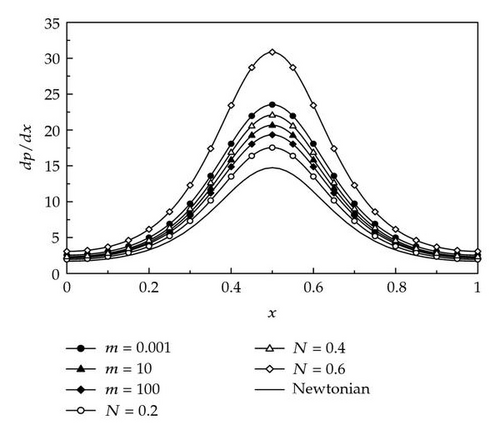
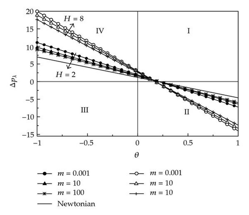

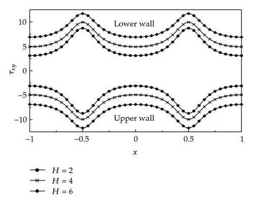
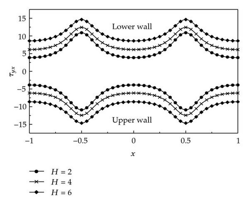
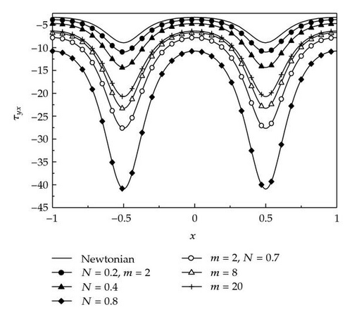
Figure 1 illustrates the variation of the axial pressure gradient with x for different values of the microrotation parameter m and the coupling number N. We can see that in the wider part of the channel xϵ [0, 0.2] and [0.8,1.0], the pressure gradient is relatively small, that is, the flow can easily pass without imposition of large pressure gradient. Where, in a narrow part of the channel xϵ [0.2, 0.8], a much larger pressure gradient is required to maintain the same flux to pass it, especially for the narrowest position near x = 0.5. This is in well agreement with the physical situation. Also from this figure, we observe the effect of m and N on the pressure gradient for fixed values of the other parameters, where the amplitude of dp/dx decrease as m increases and increases with increasing N, and the smallest value of such amplitude corresponds to the case N → 0 (Newtonian fluid). The effect of the Hartmann number H on dp/dx is not included, where it is illustrated in a previous paper [44], where the amplitude of dp/dx increases as H increases.
Figures 2 and 3 illustrate the change of the pressure rise Δpλ versus the time-averaged mean flow rate θ for various values of the parameters m (= 0.001, 10,100 with N = 0.4, α = 0.4 and different values of H) and N( = 0.2, 0.4, 0.6 with m = 2, α = 0.4 and different values of H).
The graph is sectored so that the upper right-hand quadrant (I) denotes the region of peristaltic pumping, where θ > 0 (positive pumping) and Δpλ > 0 (adverse pressure gradient). Quadrant (II), where Δpλ < 0 (favorable pressure gradient) and θ > 0 (positive pumping), is designated as augmented flow (copumping region). Quadrant (IV), such that Δpλ > 0 (adverse pressure gradient) and θ < 0, is called retrograde or backward pumping. The flow is opposite to the direction of the peristaltic motion, and there is no flows in the last quadrant (Quadrant (III)). It is shown in both Figures 2 and 3, that there is an inversely linear relation between Δpλ and θ, that is, the pressure rise decreases with increasing the flow rate and the pumping curves are linear both for Newtonian and micropolar fluid. Moreover, the pumping curves for micropolar fluid lie above the Newtonian fluid in pumping region (Δpλ > 0), but as m increases, the curves tend to coincide. In copumping region (Δpλ < 0), the pumping increases with an increase in m. Figure 3 shows the effects of the coupling number N on Δpλ, where the pumping increases with an increase in N and the pumping curve for the Newtonian fluid lies below the curves for micropolar fluid in the pumping region, and in the copumping region, the pumping decreases with an increase in N.
It is known that the stress tensor is not symmetric in micropolar fluid, that is why the expressions for τxy and τyx are different. In Figures 4 and 5, we have plotted the shear stresses τxy and τyx at the upper and lower walls for various values of the Hartmann number H. It can be seen that both shear stress are symmetric about the line x = 0. However, its magnitude increases as H increases. Moreover, both shear stresses have directions opposite to the upper wave velocity, while the directions of these shear stresses are along the direction of the lower wave velocity. Figure 6 indicates that the shear stress τyx decreases with an increase in the microrotation parameter m, while it increases as the coupling number N increases, and so, the magnitude value of shear stress for a Newtonian fluid is less than that for a micropolar fluid.
4.2. Magnetic Field Characteristics
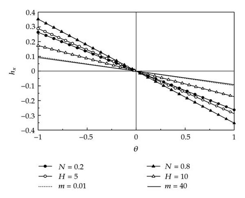
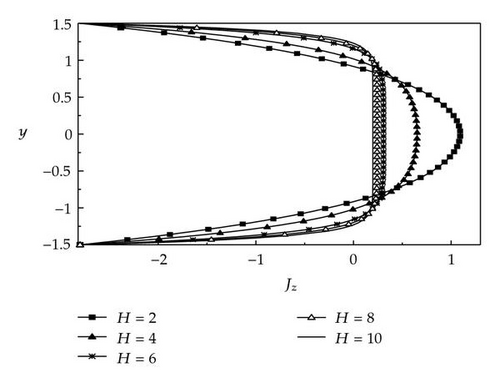
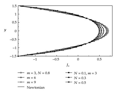
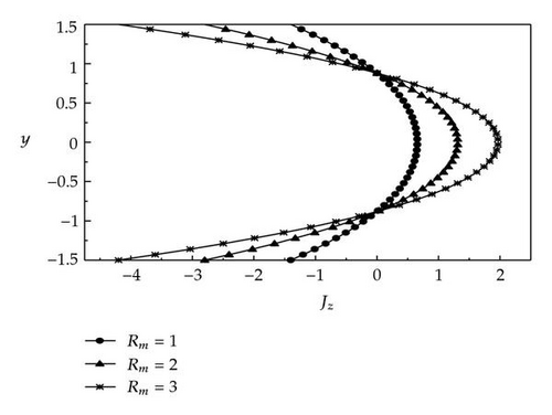
The variations of the axial-induced magnetic field hx across the channel at x = 0 and the current density distribution Jz across the channel for various values of m, N, H, Rm, and α are displayed in Figures 7–12.
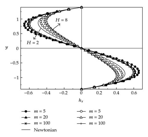
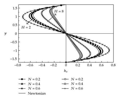
In Figures 7-8, m (= 5, 20, 100 with N = 0.9, Rm = 1, α = 0.4 and θ = 1.2 and different values of H), N (= 0.2, 0.4, 0.6 with m = 2, Rm = 1, α = 0.4 and θ = 1.2 and different values of H).
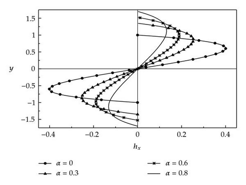
These figures indicate that the magnitude of the axial-induced magnetic field hx decreases as the microrotation parameter m and the Hartmann number H increases while it increases as the coupling number N increases. Further in the half region, the induced magnetic field is one direction, and in the other half, it is in the opposite direction and it is zero at y = 0. Figure 9 illustrates the variation of hx across the channel for different values of the amplitude ratio α at x = 0.5, where α (= 0, 0.3, 0.6, 0.9 with m = 3, N = 0.6, H = 4, Rm = 2, and θ = −1.2). It is clear that the magnitude of the axial-induced magnetic field hx at α = 0 (no peristalsis) is larger, and it decreases with increasing α. The distributions of hx within the time-averaged mean flow rate θ are exhibited in Figure 10 at x = 0.25, y = 0.5, where hx is plotted for various values of the parameters N (= 0.2, 0.8 with m = 2, H = 4, Rm = 2, α = 0.5 ), m (= 0.01, 40 with N = 0.7, H = 7, Rm = 1, α = 0.5) and H (= 5, 10 with m = 4, N = 0.6, Rm = 2, α = 0.5). From this figure, we observe that there is an inversely linear relation between hx and θ for any value of the above-mentioned parameters, that is, hx decreases with increasing the flow rate θ and that the obtained curves will intersect at the point θ = 0. It is found also that for any value of θ ≤ 0, the effect of increasing each of M and H is to decrease hx values whereas the effect of increasing N is to increase the value of hx. On the other hand, for any value of θ ≥ 0, all the obtained lines will behave in an opposite manner to this behavior when θ ≤ 0.
Figures 11–13 describe the distribution of the current density Jz within y for different values of m, N, H, and Rm at the central line of the channel (x = 0), where H (= 2, 4, 6, 8, 10 with m = 3, N = 0.2, Rm = 1, α = 0.5, θ = 1.6), m (= 3, 6, 9 with N = 0.8, H = 2, Rm = 1, α = 0.5 and θ = 1.6), N (= 0.1, 0.3, 0.5 with m = 3, H = 2, Rm = 1, α = 0.5 and θ = 1.6), and Rm (= 1, 2, 3, with m = 3, N = 0.2, H = 4, α = 0.5, θ = 1.6). The graphical results of these figures indicate that the dimensionless current density Jz decreases as H and M increase in the region near the center of the channel while it increases for the same values of H and M in the region near to the lower and upper walls, that is, the net current flow through the channel is zero and this corresponds to the case of open circuit. However, an opposite behavior is noticed as N and Rm increases. Also, the current value for a micropolar fluid is higher than that for a Newtonian fluid.
4.3. Trapping Phenomena and Magnetic-Force Lines
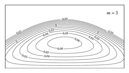
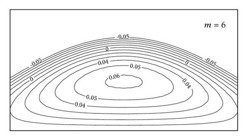
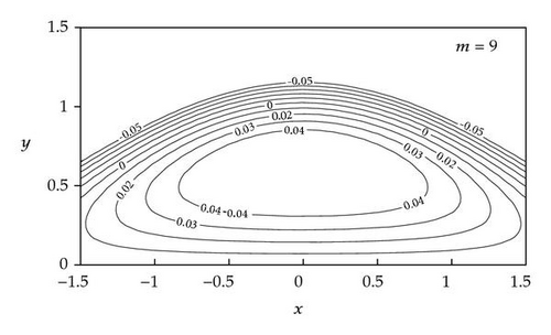
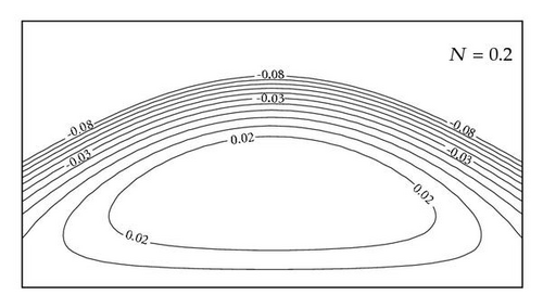
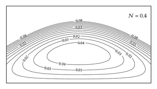
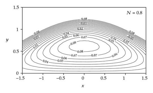
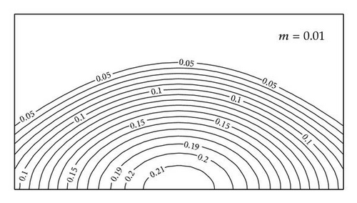
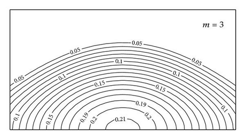
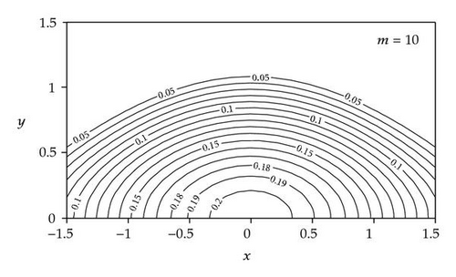
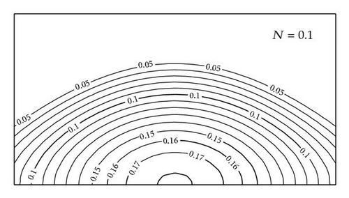
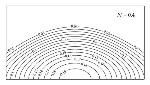
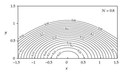
Another interesting phenomenon in peristaltic motion is trapping. In the wave frame, streamlines under certain conditions split to trap a bolus which moves as a whole with the speed of the wave. To see the effects of microrotation parameter m and the coupling number N on the trapping, we prepared Figures 14 and 15 for various values of the parameters m (= 3, 6, 9 with N = 0.5, H = 2, θ = 0.7, α = 0.5) and N = (0.2, 0.4, 0.8 with m = 7, H = 2, θ = 0.7, α = 0.5). Figures 14 and 15 reveal that the trapping is about the center line and the trapped bolus decrease in size as the microrotation parameter m increases, while the size of the bolus increases as N increases. Also the effects of m and N on the magnetic-force function ϕ are illustrated in Figures 16 and 17 for various values of the parameters m (= 0.01, 3, 10, with N = 0.5, H = 2, θ = 0.7, Rm = 1, α = 0.4) and N = (0.1, 0.4, 0.8, with m = 3, H = 2, θ = 0.7, Rm = 1, α = 0.4). It is observed that as m increases, the size of the magnetic-force lines will decrease, and for large values of m, these lines will vanish at the center of the channel. An opposite behavior will occur as the coupling number N increase, where the width of the magnetic-force lines will increase and more magnetic-force lines will be created at the center of the channel as the coupling number N increases.
5. Concluding Remarks
The effect of the induced magnetic field on peristaltic flow of a magneto-micropolar fluid is studied. The exact expressions for stream function, magnetic-force function, axial pressure gradient, axial-induced magnetic field, and current density are obtained analytically. Graphical results are presented for the pressure rise per wave length, shear stresses on the lower and upper walls, axial-induced magnetic field, and current density and trapping. The main findings can be summarized as follows.
- (1)
The value of the axial pressure gradient dp/dx is higher for a magneto-micropolar fluid than that for a Newtonian fluid.
- (2)
The magnitude of pressure rise per wavelength for a magneto-micropolar fluid is greater than that of a Newtonian fluid in the pumping region, while in the copumping region, the situation is reversed.
- (3)
Shear stresses at the lower wall are quite similar to those for the upper wall except that at the upper wall has its direction opposite to the upper wave velocity while at the lower wall has its direction along the wave velocity.
- (4)
The shear stresses decrease with an increase of m and increases with increasing N.
- (5)
The axial-induced magnetic field is higher for a Newtonian fluid than that for a micropolar fluid and smaller as the transverse magnetic field increases.
- (6)
There is an inversely linear relation between the axial-induced magnetic field and the flow rate.
- (7)
The current density Jz at the center of the channel is higher for a micropolar fluid than that for a Newtonian fluid, and it will decrease as the microrotation parameter and transverse magnetic field increases, while it increases as the coupling number increases.
- (8)
As we move from the Newtonian fluid to a micropolar fluid, more trapped bolus created at the center line and the size of these bolus increases.
- (9)
More magnetic force lines created at the center of the channel as the fluid moves from Newtonian fluid to a micropolar fluid.


