Performance of Single and Double Shaft Disk Separators
Abstract
Rotating disks separators, mounted on single and double hollow shafts, are investigated experimentally. The shaft and disks were enclosed in stainless steel housing. Many parameters were measured to study their influence on the performance of single and double shaft disk filters at various rotation speeds. These parameters are pressure inside the housing, permeate flux, and electrical power consumption. The average velocity coefficient for single and double shaft disk separators was estimated and was found to be a good criterion of module performance as well. The comparison of measured and calculated filtration flow rate at various rotation speeds was in a good agreement. The estimated average shear stress is found to be about twice in double shaft filter disk. The feasibility of double shaft disk separator in treating filtration without filter cake is highly appreciated.
1. Introduction
Shear-enhanced or dynamic filtration consisting of rotating disks relies on the presence of a shear stress at the filter media surface to reduce the accumulation of the particles. The reason for its good performance is that very high shear rates are produced with a low inlet flow, thereby resulting in low pressure drop in the module. In the classical cross flow filtration with membrane modules, the shear stress is linked to the feed flow rate which leads to the pressure drop. High shear stress is produced by increasing the tangential flow along the membrane surface and continuous circulation of the feed flow. In rotating filters, the shear stress and flow rate are unlinked because the shear stress is a function of the rotating filter disk. Dynamic filters which create relative motion between the filter media and the suspension producing high shear rate are compared with conventional cross flow filtration [1]. In this study, the average shear stress is estimated based on the power consumed by the rotating disk filter. Rotating disk within an enclosed housing has been investigated extensively in the past decades [2]. It was found that the hydrodynamics of the system is governed by the Reynolds number Re = ω · r2/υ and the axial clearance sc where ω is the rotational speed, r is the disk radius, υ is the fluid kinematics viscosity, and sc is the axial clearance between the disk and a stationary wall.
With relatively large axial gap between the disk and a stationary wall, the boundary layers are separated by a core of fluid moving at an angular velocity of (kωd), where k = ωf/ωd is a velocity coefficient and has a value of almost less than one. In recent papers [3–7], the coef-ficient k for various disks is determined by regression from peripheral pressure measurements taken on the housing rim at various angular velocities using Bernoulli’s equation. The velocity coefficient is found to be in the range 0.4-0.5 for a smooth disk. Many disks with different modification on the surface types are recently developed to increase the velocity coefficient, thereby enhancing the dynamic fil-tration performance. With eight radial vanes on the rotating disc, Schiele got k = 0.9, resulting in a dramatic in-crease of the shear stress and, of course, the power input [8].
The main objective of this study is to estimate andvalidate the average velocity coefficient, both for single and double shaft disk separators and the dynamic filtrationperformance, respectively. Additionally, we want to assess the contribution of filter overlapping by estimating the average shear stress based on electrical powerconsumption. Lastly, we would like to compare the single and double shaft disk separators based on filtration experiments.
2. Experimental Setup
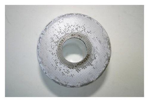
Two different geometries have been used as shown in Figure 1. The first consists of five filter disks (dp = 40 μm, ro = 45 mm, ri = 15 mm) mounted on a single hollow shaft with axial gap between two successive filter disks sg = 14 mm, see Figure 1(a). The second geometry consists also of five filter disks but mounted on two hollow shafts rotating with the same speed direction. The axial shear gap between two overlapped disks is ss = 4 mm and sg = 14 mm between nonoverlapping disks; see Figure 1(b). The whole system is placed in stainless steel housing. Permeate is collected inside each disk by a hollow shaft. The filtration unit is provided with two pressure sensors, one of which is installed inside the housing close to disk periphery while the second is mounted on the shaft where the filtrate exits. Permeate and concentrate flow rates are measured by magnetic-inductive flow meters. The filtration pressure difference can be estimated by the pressure sensors.
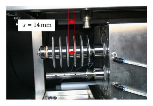
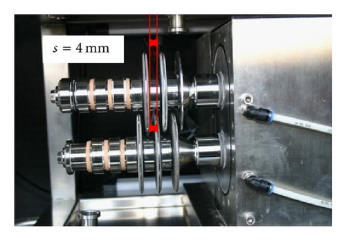
The filtration experiments are carried out using asuspension of sphere glass (mean particle size 10 μm), which is easy to prepare. The suspensions behave as a Newtonian fluid at low concentration (13.4 g/l).
3. Results and Discussion
3.1. Determination of Velocity Factor k with Water
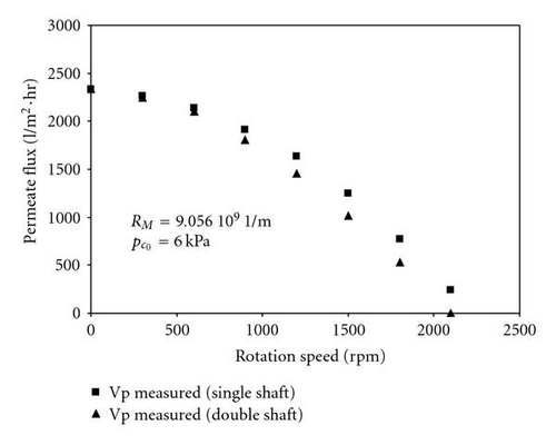
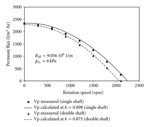
The variation of the measured filtrate flux rate with rotation speed is represented in Figure 2 for single and double shaft disk separators. The filtrate flux rate is seen to be larger using single shaft disk separator. In fact, the difference in permeate flux rate using single and double shaft disk separators refers to the average velocity coefficient . Thus, the coefficient may also be good criteria for configuration performance with absence filter cake, since higher value of will produce higher permeate flux rate according to (6). Moreover, we can expect that the torque is necessary to rotate the disk and thus the shear stress over the disks will be varied in terms of the average velocity coefficient .
3.2. Energetic Consideration
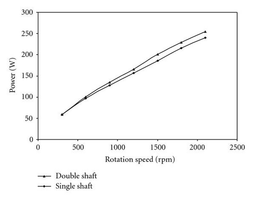
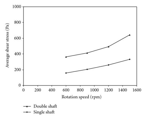
The power difference consumed by single and double shaft disk separators is converted into shear forces exerted on the disks. Thus, we were able to estimate the average shear stress over the filter surface for single and double shaft disk separators according to (7). Figure 5 shows the average shear stress for different rotation speeds using single and double shaft disk separators. It is clear that the estimated average shear stress for the double shaft filter disk is about twice as much as shear stress for the single shaft filter disk. This is due to the filter disk overlapping.
3.3. Filtration Experiments
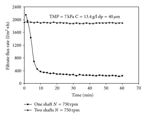
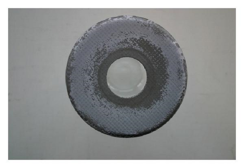
We have shown that the average shear stress for the filter disk overlapping is almost twice as large as compared to the single shaft disk separator. Thus, it is legitimate to investigate its ability in avoiding cake formation under filtration process. Therefore, filtration experiments were carried out using single and double shaft disk separators at N = 750 rpm, C = 13.4 g/l, and TMP = 7 kPa. The time dependency of the permeate flux rate were recorded for single and double shafts disk separator (Figure 6). It was found that permeate flux remains constant (steady state filtration) over time for the double shaft disk separator and decays sharply using the single shaft disk separator. The higher shear stress produced by using double shaft disk filter as shown before is mainly the reason for the free cake filter disk. The single shaft showed unsteady state filtration under the same filtration conditions. The shapes of the filter cakes, for single and double shaft disk separators, are depicted in Figure 7. The filter cake in the single shaft disk was observed to be denser and homogenously distributed over the filter surface as compared to the double shaft disk filter.
4. Conclusion
The performance of single and double shaft disk separators has been investigated. Permeate flux rate is found to decrease as the rotation speed increases for both configurations. The average velocity coefficient was estimated for both configurations and also confirmed under the filtrationprocess. It was found that the average velocity coefficient is thecriterion for configuration performance. Shear stress is enhanced by decreasing the average velocity coefficient. The power consumption is not only a function of rotation speed but is also affected by the filter geometry. It is possible to obtain steady state filtration (without cake formation) using double shaft disk separator.
Nomenclature
-
- dp:
-
- Pore diameter of the filter media (μm)
-
- :
-
- Average velocity coefficient
-
- K:
-
- Velocity coefficient
-
- Pc:
-
- Concentrate pressure (Pa)
-
- Pf:
-
- Filtrate pressure (Pa)
-
- Pe:
-
- Electrical power (W)
-
- Pm:
-
- Mechanical power (W)
-
- R:
-
- Radius (m)
-
- ri:
-
- Inner radius (m)
-
- ro:
-
- Outer radius (m)
-
- RM:
-
- Membrane resistance (1/m)
-
- sc:
-
- Axial clearance between the disk and
-
-
- wall (mm)
-
- sg:
-
- Axial gap between two rotating discs (mm)
-
- ss:
-
- Axial shear gap between two overlapped
-
-
- discs (mm)
-
- T:
-
- Shaft torque (N · m)
-
- TMP:
-
- Transmembrane pressure (Pa)
-
- :
-
- Filtrate flow rate (Lh−1 m2)
Greek Letters
-
- τ:
-
- Shear stress (Pa)
-
- :
-
- Average shear stress (Pa)
-
- μ:
-
- Fluid dynamic viscosity (Pa·s)
-
- η:
-
- Output efficiency without discs
-
- ωd:
-
- Disk angular velocity (rpm)
-
- ωf:
-
- Fluid angular velocity (rpm)
-
- ρ:
-
- Fluid density (kg/m3)
-
- υ:
-
- Fluid kinematics viscosity (m2 s−1)


