Mechanical Behaviour and Microstructure of Aluminum-Steel Sheets Joined by FSSW
Abstract
At the prospect of a lightening of the automobile structures, welded spots have been realized on a stacking of two sheets (a 6008 aluminum alloy on steel) Friction Stir Spot welding (FSSW). Different process parameters have been tested, but only the influence of the dwell time will be described in the present paper. The dwell time corresponds to the time during which the probe stays in rotation at its bottom location before extracting. A study of the microstructures and textures associated to mechanical tests (tensile shear tests) allowed determining the best set of welding parameters. The recrystallized area around the welding spot has been characterized by electron back-scattered diffraction (EBSD). A mechanism of continuous dynamic recrystallization has been identified since the misorientation of subboundaries increases close to the weld, and this is for all the dwell times tested. Elsewhere, the increase of the dwell time induced a larger recrystallized zone. It has also been found that a long dwell time induced a larger welded area but also a higher quantity of intermetallic compounds (especially FeAl, Fe2Al7, and FeAl2) with high-microhardness values (up to 800 Hv). Thus, the dwell time must not exceed a certain value, otherwise it can weaken the weld.
1. Introduction
Introducing the aluminum on the automotive structures would permit to reduce their weight [1, 2] and so to reduce the fuel consumption. However, the aluminum presents a lower mechanical resistance comparing to steel. So assembling both aluminum and steel would permit to solve this problem and then to reduce the weight of the automotive bodies. The friction stir spot welding (FSSW) is expected to provide a practical solution for joining aluminum and steel [3, 4].
This kind of bimetallic welding is still little known, and many tests and studies must be performed in order to industrialize the process. The purpose of this work consists in studying the microstructures and the recrystallization mechanisms of the aluminum steel welding according to the dwell time, in order to optimize their mechanical resistance. Some authors dedicated their works for visualizing the microstructure obtained during the linear FSW of aluminum alloys [5, 6] and the FSSW [7, 8]. Concerning the microstructural evolution on FSSW, the studies permitted to identify the different areas inside the joint [8]: the BM (base metal), the HAZ (heat affected zone), the TMAZ (thermomechanically affected zone), and the SZ (stir zone); but the recrystallization mechanisms are less touched on, and so this present work will be useful to better understand the metallurgical phenomena occuring during this process.
Moreover, the formation of brittle intermetallic compounds varies according to the welding conditions and has to be avoided as much as possible. Indeed, it has been shown that those intermetallic compounds can cause a weakening of the spot welds because of high microhardness [9, 10].
2. The Friction Stir Spot Welding (fssw)
The technique FSSW is purely mechanical. It permits an assembly without fusion and presents several advantages, especially for the materials such as aluminum, magnesium, and copper alloys, which are not easily joined with conventional fusion welding method.
The process is composed of three different steps (Figure 1). At first, the tool is formed by a probe and a shoulder is put in fast rotation (Phase 1). Under a defined effort, the shoulder gets in contact with the surface of sheets, which must be welded (Phase 2). The heat generated by friction involves a local softening of the material, and so it permits the mixing of both parts; a new metallurgical structure common to the two materials is formed. In this manner, the metallic link is insured without reaching the fusion temperature, which permits to avoid the problems which generally occur for the classical ways of welding (porosities, blisters, and cracking, etc.). Lastly, the tool in rotation is removed from the material (Phase 3), and it remains a print at the surface.
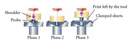
Therefore, the principal welding parameters are the rotation speed of the tool, the effort of welding, and the dwell time, which corresponds to the time during which the tool stays in rotation at the bottom of the weld and the geometry and the material used to machine the FSW tool. The quality of the spot welds depends directly on the different parameters.
3. Material and Experiments
3.1. Configuration and Materials
The studied spot welds were realized at the FSW Center of the Institut de Soudure at Goin, in France. The FSW probe is machined into rhenium tungsten alloy (W25Re), and the shoulder is made of steel Z38CDV5 treated at 50 HRC.
A 6008 aluminum alloy plate of 2.5 mm thickness is superimposed to a galvanized steel plate of 2 mm thickness. The nature of the steel used here is specific to the automotive industry. The tool has a diameter of 6 mm. As the tool is 4 mm length, it penetrates completely into the aluminum sheet and partially into the steel sheet.
Each sample was cut out (Figure 2) and mechanically polished. Lastly, the samples underwent an electrolytic polishing with a solution Struers A2 adapted to steel and aluminum alloys (made up of 60% of perchloric acid), at 20°C, with a tension of 45 V during 12 seconds.

Three samples with different values of dwell time were studied (the other parameters remained constant, with a rotation speed of 2000 rpm). From sample 1 to sample 3, the dwell time, Dt, increases from 0 second to 2 seconds.
3.2. Characterization and Analysis Methods
To make first observations on the welding, optical microscopes, SEM, and FEG/SEM were used. The scanning electron microscope was also used for the chemical analysis by EDS. Then, orientation imaging microscopy (OIM) attached to a Zeiss DSM 940 SEM was employed to evaluate grain-size distribution and grain-boundary misorientation.
To assess the fragility of the intermetallic compounds and for more complete information, Vickers microhardness tests were realized with a 100 g loaded tester, using a LECO M400H.
Analyses by microprobe were also performed to obtain the distribution of the chemical elements across the welding. Those experiments were realized at the LCMTR (Laboratoire de Chimie Métallurgique des Terres Rares) at Thiais.
Lastly, concerning the mechanical properties, some tensile shear tests were carried out.
4. Results and Discussion
4.1. Mechanical Resistance
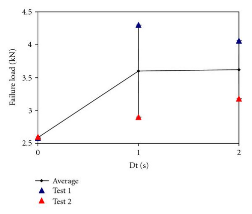
The influence of welding parameters on the mechanical resistance of the spot weld was analyzed. With the better offset of parameters, tensile shear resistance of about 4 kN has been reached. A lack of time and a lack of samples have limited the number of possible tensile shear tests. However, even if three points are not enough to reach a conclusion, the average of mechanical strength tends to show that the more the dwell time increases, the more the welding is resistant. More experiments will be realized to confirm this trend, but it seems that over a threshold the mechanical resistance stays equivalent (Figure 3). It can also be observed that there seems to be more reproductibility problems for the dwell times of 1 second and of 2 seconds, than without dwell time (0 second).
4.2. Material Flow
4.2.1. General View
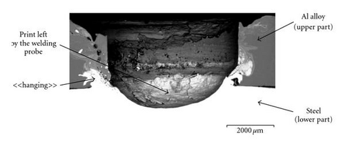
A general view of the sample was obtained using the scanning electron microscope (Figure 4). The welding holds thanks to the area called the “hanging.” It corresponds to the entrance of the steel into the Al alloy, possibly because of the stirring of the material during the welding.
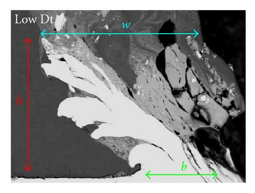
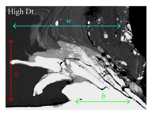
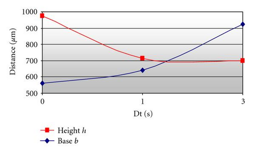
The comparison of the hangings shows geometrical differences depending on the dwell time. To understand its influence, different distances were measured: the size of the base (b), the height (h), and the width (w) of the “hanging” (Figures 5, 6). It shows that while the dwell time increases, the size of the base increases too, which can explain the better mechanical resistance obtained with a high dwell time. It also shows that when the dwell time is low, the hanging stretches mostly in height. Conversely, when the dwell time is high, the hanging stretches laterally, without gaining height.
4.2.2. Chemical Distribution
Then, by observing the cartographies obtained by microprobe (Figure 7), it can be noted that there is migration of steel into the Al alloy, Moreover, the areas with intermetallic compounds can be located. An important chemical heterogeneity exists. The maps of the chemical elements highlight also that the increase of the dwell time induces an increase of the heterogeneity of the intermetallic areas.
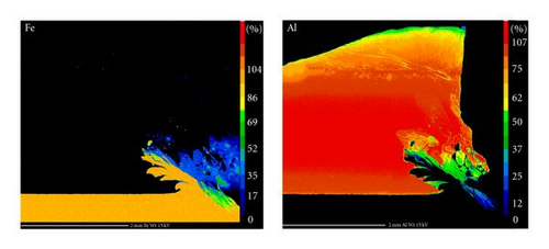
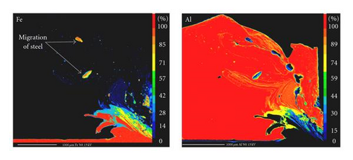
A chemical analysis was performed by EDS, and it permitted to conclude that, according to the dwell time, there are different imtermetallic compounds, which are formed during welding. Indeed, for the lower value (Figure 7(a)), there is formation of FeAl, Fe3Al. On the other hand, for the higher dwell time (Figure 7(b)), there is formation of FeAl, Fe3Al, Fe2Al7, and FeAl3. The microhardness of the intermetallic compounds which appear at the higher dwell time is much more important, and so much more weakening than for the lower (Table 1).
| Bimetallic compounds | Dwell time (s) | Al content (atomic percentage) | Structure [10] | Microhardness (HV) [10] |
|---|---|---|---|---|
| Fe3Al | 0 and 2 | 25 | Ordered body-centered cubic structure | 260–370 |
| FeAl | 0 and 2 | 50 | Ordered body-centered cubic structure | 420–520 |
| Fe2Al7 | 2 | 63 | Complex body-centered cubic structure | 620–730 |
| FeAl3 | 2 | 74–76 | Highly complex monoclinic body-centered cubic structure | 820 |
Then, the intermetallic areas have been quantified (Table 2), and it has been found that increasing the dwell time results in creating more intermetallic compounds.
| Dwell time (second) | 0 | 1 | 2 |
|---|---|---|---|
| Intermetallic compounds fraction | 0.17 | 0.18 | 0.20 |
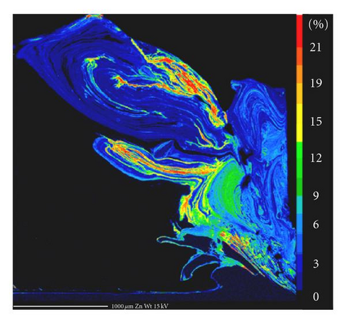
It can be noted that there are important movements of zinc inside the aluminum part (Figure 8), which comes from the galvanized layer of the steel sheet. The cartography of zinc distribution permits to observe the expanse of the area affected by zinc, with a high concentration under the shoulder. As the melting temperature of zinc is worth 420°C, it can be assumed that this element becomes liquid during welding.
4.2.3. The Cracked Areas
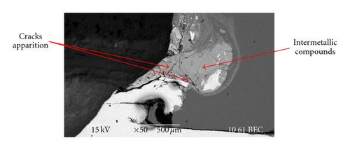
Many cracks appeared in the intermetallic areas around the hanging (Figure 9), but there are also frequent cracks at the interfaces between steel and the intermetallic compounds. These cracks may come from the passage to a molten state of the material induced by high temperatures. Then, during the cooling, the difference between the expansion coefficient of the steel and that of the intermetallic compounds may have resulted in the cracking at the interfaces.
To conclude, the weld holds thanks to the area called “the hanging.” The more “the hanging” is wide, the more the welding is resistant. As the welding is bimetallic, there is formation of intermetallic compounds at the aluminum steel interface around the hanging. It has been found that the more the dwell time is high, the more “the hanging” is wide, but also the more there is presence of intermetallic compounds, which weaken the weld because of their high microhardness [9, 10], and so which could explain the mechanical properties evolution.
4.2.4. The Microstructure of Alloys Before Welding
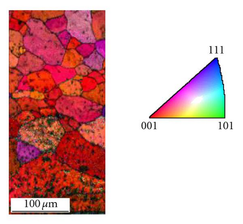
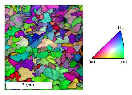
The Al alloy sheet was hot rolled. Therefore, original microstructure is composed of medium-sized grains (with a diameter between 60 and 80 μm) (Figure 10(a)). There are almost no subboundaries (defined as grain boundary which misorientation is lower than 15°). And from the obtained microstructure, it can also be noticed that most grains have a {001} plan parallel to the studied plan.
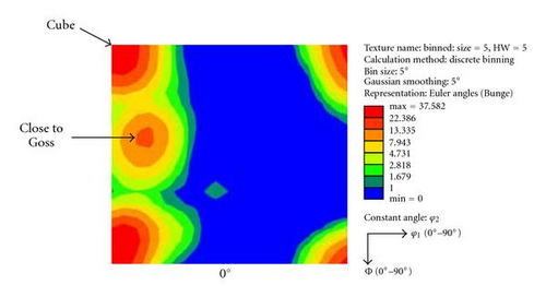
Then, the calculation of the orientation distribution function (ODF) corresponding to the aluminum before welding (Figure 10(b)) presents a classical texture composed of the cube orientation {100}〈010〉. The presence of a secondary component close to Goss orientation can be observed.
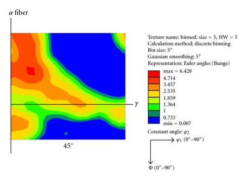
Concerning the steel microstructure, it is constituted of small grains (around 8 μm) (Figure 11). There are many grains whose plan is {101}. The obtained texture, represented in the Euler space in Figure 11(b), corresponds to a classical texture of rolling, with the presence of α and γ fibres visible on the section at φ2 = 45°. It can also be noted that the sharpness stays relatively weak because the maximum reached is only 6.4.
4.2.5. Comparison of the Microstructures Obtained with Different Dwell Times
Different orientation maps were measured by EBSD in the aluminum part, all of dimension 200 μm × 400 μm with a 1 μm step. To observe the evolution of the microstructure closer and closer to the welding spot, horizontal displacements were performed from the original microstructure to “the hanging” (Figure 12) for 2 values of dwell time (0 and 2 seconds).
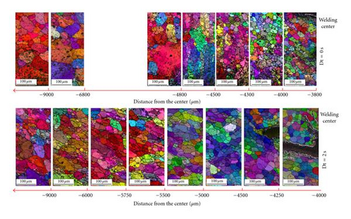
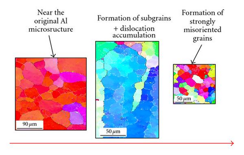
The most important difference between both dwell times concerns the extent of the recrystallized area. Indeed, for Dt = 0 second, at 9000 μm far from the weld center, the microstructure corresponds to the original one. But, on the contrary, for Dt = 2 seconds, at 9000 μm, the microstructure is still far from the original one; the grains are elongated, and it remains subboundaries. This difference is highlighted by the curve in Figure 13, which shows the evolution of the percentage of subboundaries depending on the dwell time.
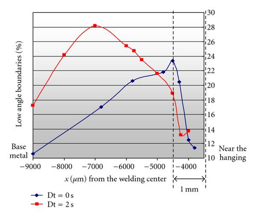
The passage from a microstructure composed of subboundaries to a microstructure without subboundaries, when approaching the hanging, corresponds to the maximum of the curves in Figure 13. Indeed, getting closer to the welding center, the mixing tends to increase the boundary misorientation. Then, when the misorientation reaches 15°, the low-angle boundaries are replaced by the high-angle boundaries, which correspond to the maximum of the curves. There seems to be a shift of this maximum depending on the dwell time because of the difference in the temperature and the deformation reached in the welds. Indeed, if we assume that the passage to a misorientation higher than 15° is associated to a critical couple (ε,T)c, it is obvious that this couple will be reached farther from the welding center for the high dwell time, as illustrated in Figure 14.

After those maxima, the decrease in percentage of low-angle boundaries is due to the transformation of low-angle to high-angle boundaries. Then, the change of slope in the curve (ε, T) at around 1 mm from the weld center can be due to the friction effect of the tool on the material. This change of slope induces the drastic drop of low-angle boundaries observed very close to the nugget (Figures 13, 14), resulting in the formation of dynamically recrystallized microstructure with small grains highly misoriented. Obviously, it remains to check this hypothesis of (ε, T) evolution by a simulation of temperature and deformation, for instance, [11].
4.2.6. Evolution of the Microstructure of the Aluminum Part After Welding
Far from the welding nugget, the microstructure is described above, that is, the microstructure of the original aluminum sheet. Then, getting closer to the welding center, there is an apparition of dislocation substructure, characterized by low-angle (misorientation <15°) boundaries inside grains. Indeed, when the temperature and the deformation increase, the phenomenon of recrystallization is more activated and so the subboundaries misorientation increases [12, 13]. Consequently, near the welding center, a recrystallized microstructure of small grains is obtained. This metallurgical phenomenon corresponds to the continuous dynamic recrystallization (Figure 15). The texture obtained close to the welding center seems to be identical with the two values of the dwell time; it is composed of the orientation {012}〈221〉, but these results must be taken with precaution because the studied areas are small and contain large grains (less than 100 grains per map), and so the statistic is poor. In order to refine the analysis of the texture, it would be better to increase the size of the analyzed areas.
5. Conclusion
This study had the aim to understand the influence of the dwell time on the microstructure around the weld. At first, it has been found that when increasing the dwell time, there seems to be an improvement of the tensile shear strength. Indeed, a long dwell time induced a larger welded area, but simultaneously a long dwell time induced a higher quantity of intermetallic compounds (especially FeAl, Fe2Al5, and FeAl2) with high-microhardness values [10] (Table 1). Thus, the dwell time must not exceed a certain value; otherwise it can weaken the weld.
Moreover, a continuous dynamic recrystallization has been evidenced whatever the dwell time is. Near the spot welding, the microstructure is composed of small equiaxed and misoriented recrystallized grains. At last, a higher dwell time tends to widen the recrystallized area.
So, to conclude, an intermediate dwell time value gives a good compromise between a sufficient width of the hanging and limited intermetallic compounds formation, in order to optimize the mechanical resistance. However, more experiments are needed to confirm the mechanical trend. Consequently, this study on the influence of the dwell time should be helpful for further works on weld parameters optimization. It is also necessary to study the other parameters that can increase temperature and strain such as the rotation speed and the welding effort. Moreover, getting information on the deformation and the temperature fields is needed.
Acknowledgments
The authors would like to thank F. Garnier and C. Rey from the MSSMat Laboratory of Ecole Centrale de Paris, and Dr. E. Leroy from Laboratoire de Chimie Métallurgique des Terres Rares (LCMTR), Thiais, France, for their help and fruitful cooperation.


