Components of mesophyll resistance and their environmental responses: A theoretical modelling analysis
Abstract
Mesophyll resistance (rm), stomatal resistance, and biochemical limitations are recognized as three critical factors limiting leaf photosynthesis. Contrary to the expectation of being a constant, rm not only varies with light and CO2 conditions but also shows different responses among species. To elucidate the mechanistic basis of these responses, we derived an analytical model of rm, which incorporates various anatomical and biochemical factors including permeabilities of cell wall and chloroplast envelope to CO2 and HCO3−, carbonic anhydrase activities in cytosol and stroma, Rubisco activities, and relative location of mitochondria and chloroplast. The robustness of this model was confirmed by comparing the predicted rm and its components to numerical models developed at cell and leaf levels, which incorporate detailed 3-dimensional cell and leaf anatomies, CO2 hydration and diffusion processes from intercellular air space to stroma, and CO2 fixation by Rubisco. A combination of these model analyses shows that the varying rm is influenced by four biochemical factors: (a) nonuniform photosynthesis status across the leaf, (b) photorespiration and respiration, (c) bicarbonate leakage on the chloroplast envelope, and (d) hydration activity in cytosol and stroma. This study provides a theoretical framework to study components of rm and their responses to environmental perturbations.
1 INTRODUCTION
Mesophyll resistance (rm) represents a series of physical barriers and biochemical components residing in the cell wall, cytosol, chloroplast envelope, and stroma, which limits CO2 diffusion and causes a gradient of CO2 from the substomatal cavity (Ci) to the carboxylation site in the chloroplast (Cc). Mesophyll resistance (rm) equals the gradient Ci–Cc divided by the flux of net photosynthesis (AN), which is defined analogous to resistance in Ohm's law for electricity (Evans, Kaldenhoff, Genty, & Terashima, 2009). It is worth noticing that the definition of rm implicitly assumes that a leaf can be averaged to one cell at a certain middle position of the leaf, ignoring the complexity of the leaf structure (Parkhurst, 1994). Recently, rm is found to be an important limiting factor to leaf photosynthesis in many species in addition to the limitation of stomatal resistance and biochemical process (Flexas et al., 2012; Griffiths & Helliker, 2013). Improving mesophyll conductance (gm), which is the reciprocal of rm, is also regarded as an ideal option to increase water use efficiency of crops (Zhu, Long, & Ort, 2010; Flexas et al., 2012).
Two classic methods are commonly used to measure instantaneous rm. One is the variable J (electron transport rate) method, in which gas exchange and chlorophyll fluorescence signals are measured simultaneously. The other is the stable carbon isotope discrimination (Δ13C) method, in which gas exchange and 13C discrimination of leaf photosynthesis are measured simultaneously (Harley, Loreto, Di Marco, & Sharkey, 1992). With the variable J method, a number of studies reported a varying rm with increase of Ci, and the patterns are surprisingly similar; that is, gm appears to first increase and then decrease gradually with the increase of Ci (Flexas et al., 2007; Hassiotou, Ludwig, Renton, Veneklaas, & Evans, 2009; Vrábl, Vašková, Hronková, Flexas, & Šantrček, 2009; Xiong et al., 2015). In addition to the CO2 response, gm is also reported to decrease with the increase of irradiance in several species (Flexas et al., 2012; Xiong et al., 2015). Recent work by Théroux-Rancourt and Gilbert (2017) combines the variable J method with a multilayer leaf model and shows gm is an emergent property of the leaf structure, whereas, with the Δ13C method, a similar CO2 and light response of rm is observed by Flexas et al. (2007) and Vrábl et al. (2009). But rm is also reported to show no response to Ci and light under low oxygen concentrations in wheat (Tazoe, von Caemmerer, Badger, & Evans, 2009). However, Tazoe et al. (2011) also observed that gm decreases with CO2 under 2% O2 and has a less sensitive response under 21% O2. Significant short-term responses to both light and CO2 were observed by Douthe, Dreyer, Brendel, and Warren (2012) and Douthe, Dreyer, Epron, and Warren (2011).
Various mechanisms were proposed to explain the CO2 and light dependency of rm. In the measurement with either variable J method or Δ13C method, a biased estimate of parameters such as the day respiration (Rd) and chloroplastic CO2 compensation point (Γ*) may influence the estimated rm (Harley et al., 1992; L. Gu & Sun, 2014; Pons et al., 2009). Current chlorophyll fluorescence measurement technologies potentially underestimate the photosynthetic electron transport rate (J; Loriaux et al., 2013), which may also affect the measured dependency of rm on CO2 and light via the variable J method (Evans, 2009; L. Gu & Sun, 2014). In the Δ13C method, different formulas of carbon isotope discrimination (Evans & von Caemmerer, 2013; Farquhar & Cernusak, 2012; L. Gu & Sun, 2014), in particular with either a constant or variable fractionation factor associated with photorespiration (f), can lead to different estimates of rm (Evans & von Caemmerer, 2013; Griffiths & Helliker, 2013; Tholen et al., 2012).
Mathematical models, in particular analytical models, provide an alternative and more intuitive approach to study rm and its environmental responses. A three-dimensional (3D) reaction–diffusion (R-D) model of a single mesophyll cell (MSC) has been developed to study mechanisms underlying the varying rm (Tholen & Zhu, 2011). On the basis of that 3D model, an analytical model of rm is derived, which incorporates the impacts of photorespiratory and respiratory fluxes (Tholen, Éthier, & Genty, 2014; Tholen et al., 2012; Tholen & Zhu, 2011). There are also other studies developing analytical models of rm since decades ago, which link rm and its components to measured anatomical features in different species (Berghuijs et al., 2015; Evans et al., 2009; Nobel, 1999; Peguero-Pina et al., 2012; Tomás et al., 2013; Tosens & Niinemets, 2012; Tosens, Niinemets, Westoby, & Wright, 2012) and quantify the contribution of the cell wall, cytosol, chloroplast envelope, and stroma to the measured rm. In these studies, parameters such as thickness of the cell wall, cytosol, and chloroplast were estimated from light microscopy and transmission electron microscopy images, whereas parameters such as wall porosity, membrane permeability, diffusion viscosity, and effective path length of CO2 diffusion were either assumed or fitted from data collected from a group of species (Berghuijs et al., 2015; Tomás et al., 2013), which can potentially lead to overparameterization. In all these efforts of developing analytical models of rm, the detailed biochemical components and the associated 3D nature of CO2 and bicarbonate diffusion in an MSC or leaf are simplified. This simplification prevents using such models in studying components of rm and their responses under different environments.
In addition to being a major tool in studying mechanisms of mesophyll resistance (Tholen & Zhu, 2011), 3D mechanistic models of mesophyll resistance can be used as a supporting tool to guide development of analytical models. Using such mechanistic 3D R-D models, we not only can test the influence of different biochemical and biophysical parameters such as dark respiration (Rd), Γ*, wall porosity, membrane permeability, and diffusion viscosity on rm but also can predict the ground truth of the responses of rm to different light and CO2 conditions.
In this paper, to facilitate our understanding of the rm of rice, which is one of the most important food for the world, we derived a new analytical model of rm, which includes all known anatomical and biochemical factors influencing rm. We validated the robustness of the model by comparing its prediction with 3D R-D models at both the mesophyll and leaf levels. With these theoretical frameworks, we systematically evaluated the magnitude and responses of rm under different light and CO2 conditions. Finally, we discuss potential errors in using this new analytical model in studying rm in the laboratory.
2 THEORY AND METHODS
2.1 An analytical model of mesophyll resistance
 (1)
(1)
 (2)
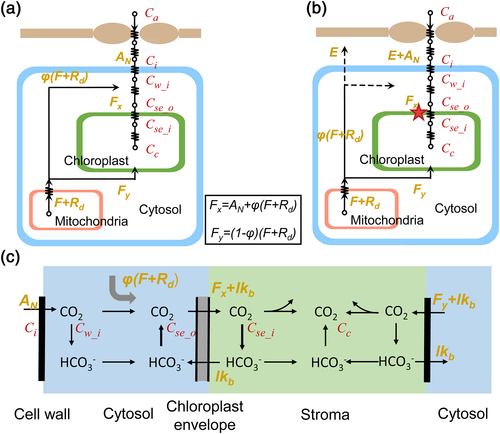
(2)In the liquid phase of diffusion, CO2 first diffuses through the cell wall and membrane, during which [CO2] decreases from Cw_o to Cw_i, that is, [CO2] at the inner surface of the cell wall. Next, CO2 diffuses through the cytosol to reach the surface of the chloroplast envelope, with the [CO2] further decreasing to Cse_o, that is, [CO2] at the outer surface of the chloroplast envelope facing the cell wall. Then the chloroplast envelope forms another barrier, where [CO2] further decreases to Cse_i, that is, [CO2] at the inner surface of the chloroplast envelope. Finally, CO2 diffuses inside the chloroplast stroma and is fixed by Rubisco, resulting in Cc, that is, the average [CO2] in the stroma (Figure 1a, extended based on Tholen et al., 2012).
In Figure 1a, the photorespired and respired CO2 from mitochondria (F + Rd) are separated into two fluxes with different diffusion paths and further refixed by Rubisco, which has been reported to be influenced by the relative position of mitochondria and chloroplast (Busch et al., 2013). Although in Figure 1a, all the (photo)respired flux F + Rd finally enters the chloroplast, in a real leaf, part of F + Rd can leak to the air (Figure 1b), which can be detected by isotope signals. However, there is no difference in the calculation of all resistances between the frameworks of Figure 1a,b because resistance merely relies on net flux across the membrane.
 (3)
(3)2.2 Resistance of the cell wall and plasma membrane
 (4)
(4)2.3 Resistance of cytosol
Resistance of the cytosol (rII_cyto) is defined as the gradient of [CO2] between the inner cell wall (Cw_i) and the outer surface of the chloroplast envelope (Cse_o) divided by AN. Inside the cytosol, there are three sources of CO2: (a) CO2 from the intercellular air space, (b) CO2 generated from dehydration of HCO3−, and (c) CO2 released from mitochondria by photorespiration and respiration. These three sources of CO2 together form the CO2 gradient in the cytosol and determine the CO2 diffusion flux across the cytosol (Figure 1c). In our approximation, the influence of the (photo)respiratory flux in the cytosol is not considered for simplicity. In other words, only the effect of CO2 diffusion and the process of hydration are included in the 1D approximation.
 (5)
(5) (6)
(6) (7)
(7)2.4 Resistance of the chloroplast envelope
The effect of relative position between the chloroplast and mitochondria is represented by a parameter φ (Figure 1). That is, a portion of the (photo)respiratory flux, φ(F + Rd), influences the CO2 gradient between the cell wall and chloroplast envelope, which will increase the net flux across the chloroplast envelope facing the cell wall from AN to Fx = AN + φ(F + Rd); see Figure 1a,b. The rest of the (photo)respiratory flux Fy = (1 − φ)(F + Rd) diffuses through the abaxial side of chloroplast.
 (8)
(8)Here, rse_c is the resistance of the chloroplast envelope for CO2.
2.5 Resistance of the chloroplast stroma
 (9)
(9)Finally, by combining these different components of rliq (Equations 4, 5, 8, and 9), we derive a complete formula for rliq. Further combining this expression of rliq with rias (Equations 1 and 2), we obtain an analytical model of the whole rm.
3 A THREE-DIMENSIONAL REACTION–DIFFUSION MODEL OF MESOPHYLL CELL RESISTANCE
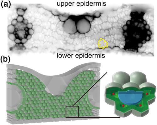
We follow the procedure of Tholen and Zhu (2011) to develop a 3D R-D model of mesophyll resistance. In this model, rice MSC is simplified to be a flower-shaped object in 3D (Figure 2b), with the intention of mimicking lobes in rice, which enhance the absorption of light and CO2 due to an increased cell surface to volume ratio (Sage & Sage, 2009). Inside each MSC, chloroplasts are simplified to be a layer next to the cell wall, and next to the chloroplast layer, one mitochondrion is distributed inside each lobe (Figure 2). The thickness of the chloroplast layer is assumed to be 2 μm, resulting in a volume percentage of chloroplasts being about 59% of the total cell volume (Sage & Sage, 2009).
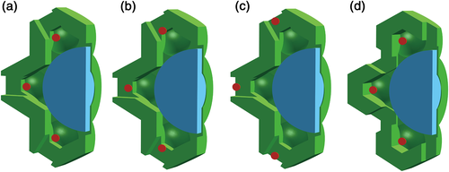
To test the effect of φ on rm in the analytical formula, four different cell structures that have different relative positions of mitochondrion to chloroplast were constructed; therefore, φ will be different in these structures. Only a quarter of these cell structures are modelled and shown in Figure 3 because the shapes are symmetrical. On the basis of the cell anatomy in Figure 2b, holes are made on the chloroplast layer to mimic gaps between the chloroplasts in a real leaf (Figure 3a). Then mitochondria are generally moved closer to the cell wall (Figure 3b,c). In addition, another kind of cell anatomy is constructed, in which holes on the chloroplast membrane are located apart from the position of mitochondria (Figure 3d). The surface area of the chloroplast layer is kept the same for all these structures in Figure 3, and gaps made here cover about 3.4% of the MSC surface.
4 A THREE-DIMENSIONAL REACTION–DIFFUSION MODEL OF A RICE LEAF
We further developed an integrated 3D model of leaf photosynthesis where internal light environment, CO2 profiles, and biochemical processes were explicitly simulated. The integrated model is an extension of the cell-level R-D model (Tholen & Zhu, 2011) using a reconstructed 3D anatomy of a rice leaf. To do this, first, the number of MSCs between two veins and the number of layers of MSCs between leaf adaxial and abaxial surfaces are estimated from transverse section images of rice leaves (Figure 2a). Then with the leaf thickness and vein distance estimated from the same images, the length and width of the MSC are calculated. Meanwhile, from the rice longitudinal cross section, the thickness of MSC can be estimated. In addition to MSCs, the shape and size of other cells such as upper epidermis, bulliform cells, lower epidermis, veins, bundle sheath cells, and bundle sheath extension cells are also reconstructed based on rice leaf cross-sectional images (Figure 2). All parameters used for reconstructing the geometry in Figure 2b are listed in Supporting Information Table S1. It is worth mentioning that in our modelled 3D leaf, the MSCs are compact and contact with each other in each transverse layer (Figure 2b), whereas between two transverse layers, the surface of MSCs is in contact with intercellular air space. Chlorophyll concentration is assumed to be the same in all chloroplasts in MSCs and bundle sheath cells, and the total chlorophyll content per leaf area for the model is 76 μg cm−2.
With this reconstructed 3D leaf anatomy, the internal light environment is simulated by a ray tracing algorithm (Xiao et al., 2016), which predicts the light absorption of the chloroplast membrane inside each cell (Supporting Information Figure S1). The predicted leaf internal light environment is then integrated with the CO2 R-D model of individual MSCs. Specifically, light absorbed by the chloroplast of individual MSCs affects the potential electron transport rate J, which further influences the photosynthetic CO2 uptake rate by limiting the ribulose 1,5-bisphosphate regeneration rate (refer to Appendix S1 for details).
5 PARAMETERIZATION AND PREDICTION OF THE THREE-DIMENSIONAL MODELS
The full list of parameters used in the 3D MSC model and 3D leaf model is detailed in Table 1. Among these, parameters related to CA-catalysed reactions and CO2 diffusion through different cellular components follow Tholen and Zhu (2011). The Rubisco-limited maximal carboxylation rate and maximal electron transport rate for the whole leaf are assigned as 115 and 216 μmol m−2 s−1, representing photosynthetic properties of a typical sunlit rice leaf (J. Gu, Yin, Stomph, Wang, & Struik, 2012). In this study, as a simplification, we assume that the Vcmax and Jmax are equally distributed into different MSCs. The 3D R-D models are implemented and solved using the finite element method (COMSOL Multiphysics 4.3, Stockholm, Sweden). The output of the model simulation is a spatial distribution of concentrations of CO2 and HCO3− and corresponding fluxes. Cc is calculated as a volume average of [CO2] in the stroma. Concentrations such as Cw_o, Cw_i, Cse_o, and Cse_i are calculated as the surface average of [CO2] on the corresponding outer or inner surface. Fluxes such as AN, F, Rd, and lkb are calculated as surface integration on corresponding surfaces. Further, for the 3D cell model, AN is calculated as the predicted photosynthesis rate per cell surface area multiplied by Sm estimated from the 3D leaf model. The ratio between the CO2 gradient Cw_o–Cc and AN is rliq. The resistance of each barrier is then calculated as the ratio between the [CO2] gradient across that barrier and AN, whereas, with the 3D leaf model, we estimate the total rm as the ratio between [Ci · (RT)/H − Cc] and AN (Equation 1).
| Parameters | Name | Symbol | Value | Units | Components | |
|---|---|---|---|---|---|---|
| Parameters used in analytical model | Biophysical and anatomical parameters | Cell wall thickness | dw | 1.5 × 10⁻⁷ | m | I |
| Effective porosity of the cell wall | p | 0.15 | unitless | I | ||
| Liquid-phase CO2 diffusion coefficient | Dc | 1.83 × 10⁻⁹ | m2 s−1 | II, IV | ||
| HCO3− diffusion coefficient | Db | 0.52 × Dc | m2 s−1 | II, IV | ||
| Cytosol viscosity | rf,c | 0.5 | unitless | II | ||
| Stroma viscosity | rf,s | 0.1 | unitless | IV | ||
| Thickness of cytosol between the cell wall and chloroplast | dc | Input | m | II | ||
| Thickness of the chloroplast | ds | Input | m | IV | ||
| Biochemical parameters | Carbonic anhydrase (CA) turnover rate | ka | 3 × 10⁵ | s−1 | II, IV | |
| CA concentration cytosol | Xa,c | 0.5 × Xa,s | mol m−3 | II | ||
| CA concentration stroma | Xa,s | 0.27 | mol m−3 | IV | ||
| Proton concentration | H | 10−pH | mol m−3 | II, IV | ||
| Cytosol pH | pHc | 7.3 | unitless | II | ||
| Chloroplast pH | pHs | 8 | unitless | IV | ||
| CA equilibrium constant | Keq | 5.6 × 10⁻⁷ | mol m−3 | II, IV | ||
| CA hydration Km | Ka | 1.5 | mol m−3 | II, IV | ||
| CA dehydration Km | KHCO3 | 34 | mol m−3 | II, IV | ||
| Other variables | [CO2] in intercellular airspace | Ci | Input | mol m−3 | IV | |
| Net photosynthesis rate | AN | Input | mol m−2 s−1 | II, III, IV | ||
| HCO3− leakage | lkb | Input | mol m−2 s−1 | II, III, IV | ||
| Photorespiration rate | F | Input | mol m−2 s−1 | III, IV | ||
| Respiration rate | Rd | Input | mol m−2 s−1 | III, IV | ||
| Mitochondria position related effect on rm | φ | Input | unitless | III, IV | ||
| Additional parameters used in the three-dimensional model | Maximal Rubisco carboxylation rate | Vcmax | 115 | mol m−2 s−1 | ||
| Maximal electron transport rate | Jmax | 216 | mol m−2 s−1 | |||
| Convexity index | θ | 0.98 | unitless | |||
| Fraction of absorbed photons which do not drive electron generation | f | 0.15 | unitless | |||
6 PARAMETERIZATION AND VALIDATION OF THE ANALYTICAL MODEL
Parameters used in the analytical models are either input for the 3D R-D models, for example, pH of the cytosol or stroma and concentrations of CA, or output from the 3D R-D models, for example, AN, photorespiratory flux (F), and the leakage of HCO3− from chloroplast to cytosol (lkb; Table 1). Such a treatment enables direct comparison between the analytical model and 3D R-D models. The parameter φ was set to be 0, considering that the coverage of the surface area of the MSC wall by the chloroplast was 100% in the rice cell modelled.
To validate the performance of the analytical solution, we calculated rm and its components using the analytical model for different light and CO2 conditions. Similarly, we modelled and estimated rm and its components using 3D R-D models at both the cell and leaf levels.
7 RESULTS
7.1 Comparison between mesophyll resistance of the liquid phase predicted by the analytical model and three-dimensional cell model
On the basis of the mathematical decomposition of mesophyll resistance (rm; Equations 1 and 3), rm is divided into resistance of the gaseous phase (rias) and resistance of the liquid phase (rliq), whereas rliq is divided into four components, namely, resistance of the cell wall and membrane (rI_wall), resistance of the cytosol (rII_cyto), resistance of the chloroplast envelope (rIII_se), and resistance of the interior stroma (rIV_chlo). Here, a new analytical model of rliq is derived by using explicit formulas for each of these four barriers (Table 1, Spreadsheet S1). The outputs of this analytical model are rliq and its components. Its input parameters for this model include (a) biophysical parameters such as permeability of the cell wall and diffusion properties of CO2 and HCO3− in different components, (b) anatomical parameters such as distance between the cell wall and chloroplast and thickness of the chloroplast, (c) biochemical parameters describing CA activities, and (d) other variables such as environmental CO2 conditions Ci, net photosynthesis rate AN, HCO3− leakage across the chloroplast envelope lkb, (photo)respiration rate, and variable φ characterizing the relative position between mitochondria and chloroplasts (Table 1, Spreadsheet S1).
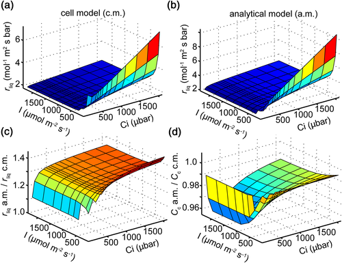
To evaluate the robustness of the new model, we first compared its predictions with a 3D R-D model of a rice MSC. Similar responses of rliq to light and CO2 were predicted by the cell model (Figure 4a) and the analytical model (Figure 4b). The ratio of rliq between the analytical model and cell model was predicted to be around 1.32 under most light and CO2 conditions. Under low light (150 μmol m−2 s−1), this ratio was slightly higher at about 1.4, whereas under low CO2 (180 μbar), this ratio became approximately 1.2 (Figure 4c). The ratio of Cc between the analytical model and cell model was predicted to be around 0.98 under different light and CO2 levels (Figure 4d).
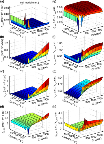
Moreover, we evaluated the robustness of the analytical model to predict individual components of rliq by comparing its prediction against those from the 3D cell model. We found that rI_wall calculated from the cell model was almost constant under different light and CO2 conditions, except under extremely low Ci (Figure 5a). The ratios between rI_wall calculated from the analytical model (Equation 4) and from the cell model were around 0.98 under most light and Ci levels (Figure 5e). Similar levels of deviation were found between predictions of rII_cyto from the analytical model (Equation 5) and the cell model under most conditions (Figure 5b,f). Even under extremely low light, the deviation was still less than 7% (Figure 5f). The deviation of the estimated resistance of the chloroplast envelope (rIII_se) between the analytical formula (Equation 8) and the cell model was less than 5% (Figure 5c,g). However, a much higher deviation was observed between the calculated resistance of the stroma (rIV_chlo) between the analytical model and the cell model (Figure 5d,h).
7.2 Influence of the relative position of mitochondria and chloroplasts on mesophyll conductance
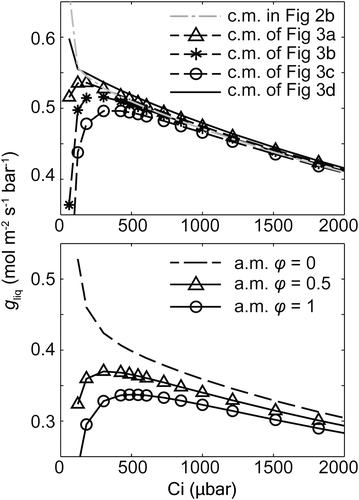
Previously, the gm–Ci curve simulated using an R-D model of a spherical MSC predicted an increasing trend of gm with Ci under relatively low Ci followed by a decreasing trend (Tholen & Zhu, 2011), and the initial increase was interpreted as the influence of the (photo)respiratory flux (Tholen et al., 2012; Tholen & Zhu, 2011). However, the CO2 response of rliq simulated by our cell model showed a monotonic decreasing trend with Ci (Figure 4a). We hypothesized that this difference was because mitochondria in our rice cell model were located completely at the inner side of the chloroplast layer.
To test this hypothesis, we built two types of cell models with four different relative positions between mitochondria and chloroplasts (Figure 3a–d). Simulation shows that the increase of gliq with Ci was directly linked to the location of mitochondria (Figure 6). When mitochondria were totally at the inner side of the chloroplast layer (Figure 3d), the simulated gliq–Ci curve showed a monotonic decreasing trend, similar to the simulated gliq–Ci curve with the default cell model in Figure 2b. When mitochondria were located in the gap between chloroplasts (Figure 3a–c), which was mimicked by holes on the modelled chloroplast membrane layer, the gliq–Ci curve gradually exhibited an increasing trend under low Ci. With a closer distance between mitochondria and the cell wall, the increasing trend became more significant and the Ci value corresponding to the peak in the gliq–Ci curve became larger (Figure 6). In our analytical model, we set a variable φ to represent this relative location of mitochondria and chloroplasts, which enables the analytical model to predict similar gliq–Ci responses (lower panel in Figure 6) as predicted by 3D cell models (Figure 3 and upper panel in Figure 6).
7.3 Comparison between the whole mesophyll resistance predicted by the analytical model and three-dimensional leaf model
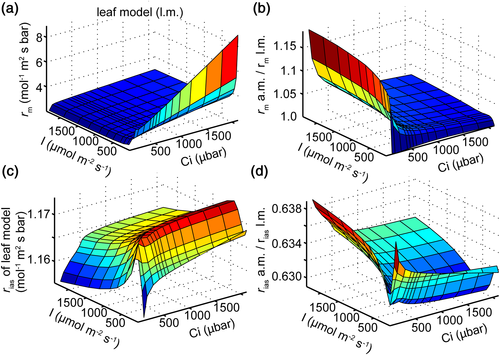
Scale factor Sm is applied in the analytical formula and the 3D cell model to convert resistances expressed on the basis of exposed cell wall surface area to resistances expressed on the basis of leaf area. This implicitly assumes that the photosynthetic statuses of all MSCs are uniform across the leaf, that is, acting as a single big MSC. However, the light and CO2 environments inside the leaf are nonuniform (Supporting Information Figures S1 and S2a). With a 3D R-D model of a rice leaf, we also compared the whole rm predicted by our analytical model and the 3D leaf model. Figure 7a shows the rm predicted by the leaf model under different light and CO2 conditions, and Figure 7b shows that the ratio of rm predicted by the analytical model and the leaf model varies between 1.03 and 1.18 under different light and CO2 levels. Specifically, Figure 7c shows the calculated rias by the 3D leaf model. The predicted rias by the analytical formula (Equation 2) underestimated the value predicted by the leaf model by around 37% (Figure 7d).
7.4 Biochemical factors influencing the mesophyll resistance
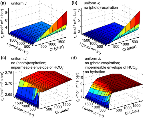
Mesophyll resistance is analogous to the resistance in Ohm's law. The resistance in electricity is not influenced by either voltage or currency; therefore, it is expected that rm is not influenced by CO2 conditions or the photosynthetic rate. We explored the potential biochemical factors leading to this variable rm under different conditions. Specifically, we sequentially eliminated four potential biochemical factors in the 3D leaf model. First, the effect of nonuniform distribution of light was eliminated by manually assigning the leaf electron transport rate (J) into all chloroplasts uniformly (Figure 8a and Supporting Information Figure S2b). Further, the potential impact of photorespiration and respiration fluxes on rm was eliminated by setting the Г* to be zero so that no CO2 will be released from the mitochondria (Figure 8b). Moreover, the bicarbonate leakage at the chloroplast envelope was blocked by manually setting the permeability of bicarbonate through the envelope to be zero (Figure 8c). Finally, (de)hydration activities in cytosol and stroma were removed in the R-D equation (Figure 8d). The corresponding rm of each model under different light and CO2 levels was predicted. We found that these four factors all contributed to the variation of rm under different light and CO2 conditions. When all these different biochemical components were eliminated, we obtained a constant rm under different light and relatively high CO2 levels (Figure 8d). Under this situation, there are only CO2 diffusion and carboxylation in the 3D leaf. When the leaf was not CO2 saturated, an increase of rm with Ci was still observed due to the change of effective path length under the 3D nature of diffusion (Figure 8d).
8 DISCUSSION
8.1 A new analytical formula representing mesophyll resistance as a property of a complex biophysical, biochemical, and anatomical system
Mesophyll resistance (rm) is an integrative leaf parameter jointly controlled by a large array of complex biophysical, biochemical, and 3D anatomical factors. Tholen et al. (2012) developed an analytical model of rm, which incorporated the effects of (photo)respiratory fluxes. A number of studies have measured anatomical features and rm of different species and used them to parameterize rm models (Berghuijs et al., 2015; Peguero-Pina et al., 2012; Tomás et al., 2013; Tosens et al., 2012). In these models, resistances of different barriers (cell wall, cytosol, chloroplast envelope, and chloroplast stroma) were calculated based on (a) the measured thickness of the cell wall, cytosol, and chloroplast and (b) assumptions about diffusive properties such as effective diffusive path length, porosity, and viscosity (Tomás et al., 2013). Recently, Berghuijs et al. (2015) combined the frameworks of Tholen et al. and Tomás et al. (2013) to produce a new rm model, with which the impacts of (photo)respiratory flux and leaf anatomical factors on rm can be explored.
Here, with a mechanistic 3D R-D model to set as the ground truth, we developed a new analytical formula of rm, which explicitly incorporates all known anatomical and biochemical components of rm. Values set in the 3D R-D model such as porosity, viscosity, Г*, and Rd can be directly used in the analytical formula, which enables us to directly evaluate the accuracy of analytical models to predict not only the whole leaf rm but also its components. Here, we compare the prediction from our new analytical model with earlier rm model predictions by Tomás et al. (2013) and Tholen et al. (2012). The formula of resistance of intercellular air space (rias, Equation 2) and the formula of resistance of the cell wall and plasma membrane (rI_wall, Equation 4) are the same between our new model and the model by Tomás et al. Compared to rias predicted from the 3D leaf model, rias was underestimated by this formula (Figure 7d), which suggests that the accuracy of this formula may be influenced by different structures of intercellular air space. In other words, tortuosity under different leaf anatomies needs to be incorporated later into this formula, as suggested by Parkhurst (1994).
For the resistance of cytosol, Tomás et al. (2013) predicted a resistance equal to 0.6 mol−1 m−2 s bar without considering the hydration process. Our formula (Equation 5), which explicitly considers the hydration process, predicted that under a Ci of 30 μbar and a photosynthetic photon flux density of 800 μmol m−2 s−1, the total cytosolic resistance (rII_cyto) was 0.34 mol−1 m−2 s bar (Figure 5b,f), whereas among this, the resistance due to limitation from hydration catalysed by CA (rII_cyto_CA) was 0.26 mol−1 m−2 s bar (76% of rII_cyto). Therefore, although the facilitation of CO2 diffusion by hydration decreased the resistance of cytosol significantly, the hydration rate catalysed by CA also contributed to rII_cyto substantially, which was earlier attributed to the nonequilibrium status of the hydration reaction in cytosol (Tholen & Zhu, 2011). For the resistance of the chloroplast envelope, Tomás et al. calculated it to be 0.39 mol−1 m−2 s bar, whereas our analytical formula (Equation 8) and 3D cell model predicted this resistance to be mostly around 0.5 to 0.8 mol−1 m−2 s bar under various conditions (Figure 5c,g). This difference between predictions using our new analytical model and the Tomás et al. model is caused by the HCO3− efflux on the chloroplast envelope in our analytical formula. Theoretically, this leakage of HCO3− will be influenced by pH, [CO2], activity of CA in the cytosol and stroma, and the permeability of the envelope to HCO3− (Tholen & Zhu, 2011). Our new analytical model provides an opportunity to explore these different factors.
For the resistance of the stroma (rIV_chlo), Tomás et al. (2013) calculated it to be as high as 7.56 mol−1 m−2 s bar, which is equal to the ratio between half the chloroplast thickness and CO2 diffusion coefficient in the stroma. However, the rIV_chlo predicted from our 3D cell model was mostly less than 0.5 mol−1 m−2 s bar (Figure 5d). This much lower rIV_chlo is attributed to two factors: (a) the facilitated diffusion by CA and (b) carboxylation occurring throughout the stroma instead of being at the midpoint of the stroma as assumed by Tomás et al. Our analytical formula considers the effect of hydration; therefore, the relative error for rIV_chlo is smaller but still as high as around 200% (Figure 5h), which is the main reason leading to the relative error of 32% for the total rliq (Figure 4c). Two factors contributed to this high relative error. First, as a result of the diffusion into an ever-decreasing volume inside a 3D chloroplast, the concentration and fluxes of CO2 and HCO3− on a unit volume basis gradually increase with depth into the chloroplast. This is analogous to the situation when CO2 diffuses from the stomata to intercellular air space, which is essentially diffusion in an ever-increasing volume in 3D (Parkhurst, 1994). This 3D nature of diffusion is ignored in the analytical model. Second, rIV_chlo is calculated as the ratio of Cse_i–Cc and net photosynthesis rate, where Cc is an average value of [CO2] in the whole stroma and Cse_i is the [CO2] in the inner boundary of the chloroplast envelope. An accurate estimate of Cc requires an accurate prediction of the distribution of [CO2] in the stroma, which is difficult to achieve in the 1D analytical model. Furthermore, because rIV_chlo is the last component of the rm, Cc is numerically close to Cse_i in the R-D model, and the difference between Cc and Cse_i is very small; as a result, even a 3% deviation in the calculated Cc between the analytical model and 3D cell model can generate an over 200% deviation in the calculated rIV_chlo, as compared to the 3D cell model.
 (10)
(10) (11)
(11)During the deduction of our analytical model, the fluxes AN, F + Rd, and lkb were preserved in the formula of rII_cyto, rIII_se, and rIV_chlo (Equations 5, 8, and 9), and those fluxes cannot be eliminated like Cw_i, Cse_o, and Cse_i. Essentially, it is because rm is a parameter defined on an indivisible complex system. Although it seems that we can divide the rliq into four components by Equation 3, any changes in the resistance of one barrier would affect the resistances of the other three barriers. This coupling between different components of rm is manifested through fluxes AN, F + Rd, and lkb in the analytical model.
8.2 Practical considerations during the application of the new analytical model
Comparison studies show that our analytical model can predict the rm with a high level of accuracy (Figure 5). However, during applications on real leaf, the calculated rm using the analytical model can potentially deviate from the rm experimentally measured due to a number of reasons. First, the formulas of rI_wall may still possibly deviate, although it seems to have a very high accuracy compared with the 3D model (Figure 5e), as effective porosity of the cell wall in the formula of rI_wall may vary between different species. Different leaves have different structures of intercellular air space, which also affects the accuracy of the formula of rias without changing the tortuosity.
Second, during the application of our analytical model (Spreadsheet S1), AN and F + Rd per leaf area can be experimentally measured. So far however there is no method developed for the measurement of lkb. In this study, we estimated lkb under different light and CO2 levels from the 3D R-D models. Then the estimated lkb was applied in the analytical model to correct the effect of bicarbonate leakage to rm. Simulations with our leaf model show that the ratio of lkb to A was around 0.27 to 3 under most light and CO2 conditions in our model (Supporting Information Figure S3). Under ambient CO2 and relative high light (e.g., photosynthetic photon flux density > 400 μmol m−2 s−1), this ratio was predicted to be between 0.27 and 0.54 (data attached in Spreadsheet S1). This ratio can potentially be different under different CA concentrations and pH in cytosol and stroma, which is at this point not considered in the current analytical model. More work is needed still to measure lkb to better use our analytical approach.
Furthermore, the factor φ in our analytical model, which represents the effect of relative special location between mitochondria and chloroplast on rm, is also difficult to estimate directly from the anatomical measurements of leaf. For plants such as rice, which has a very high chloroplast coverage, we can approximate φ to be 0. However, for other leaf anatomies, the best way to infer φ is possibly through numerical estimation based on sophisticated 3D modelling. Especially for leaf with a low chloroplast coverage, the rm is influenced not only by the scale factor Sc but also because of the effect of φ. Moreover, it is worth noting that the value of φ is not necessarily a constant under different light and CO2 conditions, considering the relative changes in AN and F + Rd with the change of environmental conditions.
In Table 2, we list all these contributing factors that can potentially decrease the accuracy of the analytical model and hence are potential areas of future research. Briefly, deviation between rm calculated by our analytical model and rm measured on a real leaf is introduced during three steps, that is, during simplification of the 3D cell model to the analytical model, during simplification of a 3D leaf model to a 3D cell model, and during representation of a real leaf into a 3D leaf model.
| Scopes | Potential errors that affect mesophyll resistance |
|---|---|
| Real leaf versus 3D leaf model | Deviations made in experimental measurement of gas exchange, chlorophyll a fluorescence, and carbon isotope discrimination |
| Representative modelled leaf anatomy | |
| Assumed parameters difficult to measure in the model (porosity of the wall and membrane, diffusive viscosity, etc.) | |
| Simplifications made during the modelling process | |
| Factors not modelled and beyond our current knowledge | |
| 3D leaf model versus 3D cell model | Representative cell anatomy; estimation of Sm/S |
| Nonuniform photosynthesis inside the leaf | |
| Resistance of the gaseous phase in different 3D leaf anatomies | |
| 3D cell model versus analytical model | 3D nature of diffusion and one-dimensional approximation |
| Accuracy of the form of the analytical model | |
| Accuracy of the input parameters of the analytical model | |
| Chloroplast arrangement and mitochondria position; parameter of φ |
8.3 Does photorespiration and respiration influence the mesophyll resistance?
Tholen and Zhu (2011, 2012) suggested that photorespiration and respiration led to the intrinsic decrease of rm under low Ci. Evans and von Caemmerer (2013) measured the response of Δ13C signal to oxygen concentration and observed that fractionation of photorespiration (Δf) responded in a linear way to the oxygen concentration; therefore, they suggested a higher factor f (fractionation factor of photorespiration) to explain the decrease of rm under low Ci. Evans and von Caemmerer (2013) explained the results of Tholen et al. (2012) by artefacts with the equation of Δ13C signal and biased f used in the data analysis (Griffiths & Helliker, 2013). However, due to the unknown real value of f, we still cannot rule out the possibility that (photo)respiration influences rm. In other words, (photo)respiration may still affect the intrinsic rm and then affect the measured rm by the Δ13C method. Meanwhile, it may also affect the factor f therefore involved in the interpretation of the Δ13C signal and the calculated rm (Griffiths & Helliker, 2013).
In our simulation, we showed that the position of mitochondria affected the response of rm with Ci (Figures 3 and 6), and a factor φ was introduced to represent this effect, which means only part of the (photo)respiratory flux, φ(F + Rd), influenced the CO2 flux between the cell wall and chloroplast. In this sense, theoretically, φ would influence both the value of f and the degree of the effect of (photo)respiration on rm. The interaction between the position of mitochondria, f, and the (photo)respiratory flux was not considered in previous experiments and simulations. A new model of the R-D process of 13CO2/12CO2 in the future can potentially form a unified theoretical framework to simulate the measured Δ13C signal and to disentangle the mechanism(s) contributing to the variation of rm under different environments.
9 CONCLUSION
This study develops a set of models that can be used together to dissect anatomical and biochemical factors controlling mesophyll resistance (rm), one of the most important parameter controlling photosynthetic efficiency. The new 3D model, which incorporates light propagation and CO2 R-D processes in a leaf, can be used to study the effects of manipulating each individual biochemical, biophysical, and anatomical leaf features on rm. With this model, we showed that nonuniform light distribution, (photo)respiration, bicarbonate leakage on the chloroplast envelope, hydration process, and anatomical features can influence rm and hence can be potential targets to manipulate for improved rm. We then focus on one 3D cell from the 3D leaf model and found that the relative position of mitochondria with chloroplast greatly influence rm. Using the predictions from this one 3D cell as ground truth, we derived a comprehensive biochemical–biophysical–anatomical formula of mesophyll resistance incorporating all these identified factors. The new analytical model shows a reliable accuracy in predicting the resistance of different barriers and the chloroplastic CO2 concentration and provides a relatively easy-to-use tool to evaluate the effects of these different factors on rm for a particular leaf. The identified factors related to rm and the models developed here will not only facilitate future mechanistic study of rm but also support current effort of engineering rm for improved photosynthesis.
ACKNOWLEDGEMENTS
The authors would like to thank Tom Sharkey and two anonymous reviewers for their constructive comments and Danny Tholen for his helpful comments and discussions on the manuscript. Funding for authors' research is from the Bill and Melinda Gates Foundation (grants OPP1014417, OPP1060461, and OPP1129902), the Chinese Academy of Sciences (XDA08020301), National Science Foundation of China (grant 30970213), Ministry of Science and Technology of China (grants 2011DFA and 2015CB150104).


