Gradient-Guided Local Disparity Editing
Abstract
Stereoscopic 3D technology gives visual content creators a new dimension of design when creating images and movies. While useful for conveying emotion, laying emphasis on certain parts of the scene, or guiding the viewer's attention, editing stereo content is a challenging task. Not respecting comfort zones or adding incorrect depth cues, for example depth inversion, leads to a poor viewing experience. In this paper, we present a solution for editing stereoscopic content that allows an artist to impose disparity constraints and removes resulting depth conflicts using an optimization scheme. Using our approach, an artist only needs to focus on important high-level indications that are automatically made consistent with the entire scene while avoiding contradictory depth cues and respecting viewer comfort.
1. Introduction
Stereoscopic images provide the viewer with a better understanding of the geometric space in a scene. Used artistically, it can convey emotions, emphasize objects or regions and aid in expressing story elements. To achieve this, stereo ranges are increased or compressed and relative depths adapted [GNS11]. Nevertheless, conflicting or erroneous stereo content can result in an uncomfortable experience for viewers. In this regard, stereo editing is a delicate and often time-consuming procedure, performed by specialized artists and stereographers. Our solution supports these artists by allowing high-level definitions to set and modify stereo-related properties of parts of a scene. These indications are propagated automatically, while ensuring that the resulting stereo image pair remains plausible and can be viewed comfortably.
For a known display and observer configuration, the terms depth (distance to the camera), pixel disparity (shift of corresponding pixels in an image pair) and vergence (eye orientation) are linked [Men12]. For the sake of simplicity, we will use these terms interchangeably throughout this paper. Although disparity is typically a function of camera parameters and the object that is observed, stereographers manipulate depth content to influence disparity. While some artists work with two-dimensional (2D) footage only [SKK*11], we will focus on three-dimensional (3D) productions, where disparity values can be changed by interacting with the 3D scene, that is changing the depth extent and position of objects.
Modifying depth directly can result in depth cue conflicts and affect the observer's interpretation of the scene, which can cause visual discomfort. For example, in Figure 1 the background wall was moved away from the viewer (by increasing its disparity), while the lion head was extended in depth. These edits result in conflicts with the rest of the scene: the lion head appears to extend beyond the wall and the wall seems detached from other scene elements.


- A formalization of stereo editing tools and conflicts.
- A real-time method to optimize scene disparity.
- A solution to avoid dis-occlusion or temporal artefacts.
2. Related Work
Over the last century, stereo vision and depth perception has received much attention from the clinical and physiological perspective. A detailed explanation of the mechanisms involved in human stereo vision can be found in [Ken01] and [How12]. More recently, work has been devoted to understanding discomfort and fatigue related to distortions present in stereo image displays. Lambooij et al. [LFHI09] and Meester et al. [MIS04] provide reviews that detail distortion effects in stereoscopic displays and their effect on viewer comfort. In particular, vergence and accommodation conflicts [BJ80, HGAB08, BWA*10] are a leading cause of visual fatigue, which can be reduced by keeping depth content to a depth comfort zone. Camera parameters can be automatically adapted for this purpose in virtual scenes [OHB*11] or even real-life stereoscopic camera systems [HGG*11]. Other methods to reduce discomfort rely on post-processing[KSI*02] of the final stereo pair, introducing blur [DHG*14], and depth of field effects [CR15].
Research towards perceptual stereo models can also help reduce or eliminate viewer discomfort [DRE*11, DRE*12b, DMHG13]. Such models can also be used to enhance depth effects, for example using the Cornsweet illusion [DRE*12a], adding film grain to a video [TDMS14] or efficiently compressing disparity information [PHM*14]. Templin et al.[TDMS14] and Mu et al. [MSMH15] modelled user response times for rapid disparity changes, such as video cuts, which allows artists to know when fast vergence changes will be acceptable for observers. In the context of stereo content editing and post-process, rotoscoping [SKK*11, LCC12] is a widely used technique, where image elements are placed in layers at different depths. The depth of these layers can be moved and scaled, and commercial products[PFT, Mis, Ocu] are available to facilitate this process. Some of these tools can detect colour inconsistencies between the stereo pair images and also possible violations to the stereo vision comfort zone, but the detection and correction of depth conflicts is left to the artist. Furthermore, Wang et al. [WLF*11] provide tools to insert depth information to a 2D image via scribble-based tools and the use of an image-aware dispersion method.
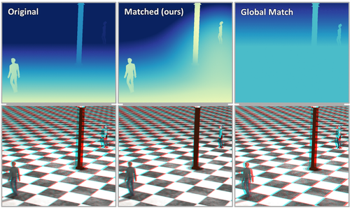
Other artistic stereo editing methods focus on globally modifying the available depth range, akin to global tone-mapping used in images. Wang et al. [WZL*16] and Kellnhofer et al. [KDM*16] propose different methods to modify disparity globally in order to enhance depth perception in certain areas of an image pair or stereoscopic video. Lang et al. [LHW*10] present a method to automatically create and apply a global disparity warping that affects the complete scene but does not allow for localized editing (see Figure 4). Optimizing for depth perception during motion in depth [KRMS13] and parallax motion [KDR*16] have also been explored.
Nevertheless, most of the previous approaches do not allow for user-defined local edits, which are common in movie productions, or they do not ensure consistency after an edit has been made. Our work addresses this problem. We will rely on a global optimization strategy that shares similarity with gradient-guided optimizations that have been explored in different settings, for example editing and filtering [PGB03, BZCC10], video editing [FCOD*04] or image stitching [LZPW04]. Luo et al. [LSC*12] propose an automated system for stereoscopic image stitching that can preserve borders and correct perspective projection. They do so via a gradient-preserving optimization process similar to Perez et al. [PGB03], but unlike the work presented here, it targets images with no defined underlying mesh and only handles the use case of image-stitching.
3. Disparity Editing
The goal of our proposed method is to allow an artist to edit disparity values for a given view of a 3D scene without having to consider potential conflicts. In this context, we strive for real-time performance to be able to provide instant feedback.
To explain our solution, we will first describe how we will model the tools that influence the original scene disparity (Section 3.2). In practice, this process will be linked to a disparity map, which, for a given view, stores in each pixel a disparity value (Section 3.1). Our algorithm will derive an optimized disparity map, integrating the artist's constraints defined with the aforementioned tools, while avoiding depth conflicts (Section 3.3). To additionally prevent artefacts due to hidden geometry and temporal changes, we rely on a scene re-projection technique. It transfers the information from this disparity map to the 3D scene, which is then rendered to an image pair following the disparity map (Section 3.4). Figure 2 showcases the different stages involved in our approach.

3.1. Disparity map
The disparity map stores the final pixel disparity between the left and right view as an image taken from a camera located precisely between the left and right view. This map can be derived very efficiently by rendering the scene from the middle camera and converting the depth buffer by taking the focal plane distance and the inter-axial distance of the stereoscopic cameras into account [Men12]. We refer to this unedited disparity map as  .
.
The tools we will provide to the user will influence this disparity map. As user commands might cause conflicts or inconsistencies, a depth conflict resolution strategy will override them where necessary before performing an optimization.
 that will be linked to the optimized disparity map
  via a set of linear equations:
 (1)
(1) .
.For brevity and readability, we will use subscripts to refer to the sampling of these maps, that is  instead of
  . Likewise, the first and second component of
  will be noted as
  and
and  , respectively.
3.2. Disparity tools
We will describe several editing tools, which are found in actual practice [SKK*11]. These tools act on properties of individual objects, properties relating pairs of objects or world-space points and global parameters. We will express their effect directly in terms of constraints for the optimized disparity map or its target gradient.
3.2.1. Roundness
Roundness refers to a change of an object's disparity range. Increasing roundness is commonly used to put emphasis on main objects or to convey emotion; in the movie UP, the roundness of the main character contrasted drastically with the roundness of a happy character when the latter approached his house to express the different emotional states.
 corresponding to the manipulated object :
 (2)
(2)3.2.2. Disparity anchoring
 to the initial disparity. As roundness will affect the disparity as well, we include it in the computation:
 (3)
(3) is the object's centre point disparity.
3.2.3. Interface preservation
Interface preservation is used to maintain the local depth contrast between objects. It is known that local depth contrast can have a global effect [AHR78, DRE*12a]. Further, it helps separating objects clearly in space.
We allow users to specify pairs of objects for which the disparity difference should be maintained. Consequently, the pixels on the shared boundary maintain their disparity gradient  . This definition can also be extended by allowing the user to draw a pixel mask to indicate where the disparity gradient should remain unaffected. This option is particularly useful for static imagery in the background.
3.2.4. Matching points
Besides overlapping objects, a user can also couple the disparity of different elements in the scene. For example, in a view of a soccer ball flying through the air, one might want to keep the disparity between player and soccer ball constantly at the limit of the comfort zone to obtain the highest comfortable depth contrast. A more subtle application is for objects that are in contact. Figure 1 shows an example, where the wall has been moved back. The attached objects become disconnected and appear to float in the air. An artist can easily connect the objects to the wall using matching points.
 to match the disparity of a source point
  plus an optional offset
  . This constraint affects the disparity value of a set of screen-space points
  defined as belonging to the object indicated by
  , or, optionally, a specified area around
  . For all points p within
  , the constraint attempts to maintain the original disparity difference between p and
  , but takes as pivot point
  instead of
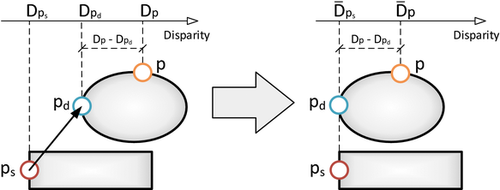
  (Figure 3):
 (4)
(4)
3.3. Disparity map optimization
 which minimizes the sum of a per-pixel energy function E over all pixels:
 (5)
(5) (6)
(6) , the gradient energy term, is the sum of the square difference of the sides of Equation 1, defined for all pixels.
 , the disparity anchor term, is the square difference of Equation 3. It is present for the pixels corresponding to objects for which an anchor disparity has been defined.
 , the matching points term, comes from the squared difference of the sides of Equation 4 for each matching point defined. Each set of matching points has a different pixel influence set θ.
 , the regularization term, ensures that there is a single solution in the absence of user defined constraints. It is defined for all pixels with a very low weight factor.
The gradient energy term ensures that the solution follows the target disparity gradient and that discontinuities or edges are correctly preserved. The target gradients are created using Equation 2 for intra-object gradients. For inter-object gradients, we use the gradient of  , which is the field we obtain by applying Equation 3; this is the edited disparity map showcased in Figures 1 and 8–11. Finally, for areas where interface preservation is specified, we revert to the original disparity map gradient.
Before the optimization procedure is performed, the linear system is inspected and modified to avoid depth inconsistencies which can potentially arise from using the tools. The most important inconsistencies are depth inversions, where for two overlapping objects, one should be behind another but their disparities imply the opposite. Such changes are reflected by differing signs of the gradient in the original and goal map gradients, which makes them easy to detect. In this case, the target gradient can be reset to the original gradient. Our framework can be expanded to deal with other conflicts in a similar fashion. For example, depth conflicts can arise at image borders for objects that are supposed to appear in front of the screen, as they are cut by the screen boundary. This case can be solved by adding an appropriate constraint to the system that penalizes pixel disparities larger than the pixel distance from the nearest vertical image border.
In general, the weight of each user-defined constraint is initialized to a default value of one and can be controlled by the user manually and intuitively since we provide instant feedback. However, some effects may only be required when viewing an object from a certain direction, or at a specified distance. Especially in image sequences, an artist may want a smooth transition between different sets of constraints when the camera or scene objects move. Our system provides the means to control the weight of a specific constraint based on different geometrical factors. A video showcasing this use case is included in the Supporting Information.
Given that we follow a target gradient, the final optimization method is a modified Poisson reconstruction problem with added screening constraints. For large resolution images, directly solving the linear system is usually infeasible due to memory constraints, and thus iterative methods are preferable, such as Jacobi, SOR or gradient descent methods[LH95]. For our implementation, we opted to use a GPU-based multi-resolution solver, since it maps well to GPU usage, avoids expensive GPU–CPU memory transfers and is fast enough to provide real-time results. We create successively halved resolution versions of the full-resolution grid (via rendering or sampling), and solve each one with ten iterations of the Jacobi method. The initial solution for each grid level is obtained by up-scaling the solution for the next coarser grid and the coarsest grid is initialized to  . We create the initial disparity value for pixel
  in the finer grid level f using the optimized disparity value of pixel
  in coarse grid level c using the formula
  , where the disparity map superscript denotes the grid level used. This formula uses the nearest pixel at the lower resolution grid, and adds the disparity difference in
  to ensure that discontinuities are preserved between source and destination.
3.4. Stereo image creation
In principle, one can create a stereoscopic image pair by warping a middle-view image according to the optimized disparity map [DRE*10]. Unfortunately, such image-based procedures can lead to holes due to dis-occlusions that reveal content not visible from the middle view. In the case where the only available information is a single segmented image plus a depth or disparity estimation, this is the best possible solution.
A more interesting case arises when we have access to the complete scene information. In this situation, we can provide a more robust solution that relies on assigning a disparity value to each mesh vertex based on the optimized disparity map. With a per-vertex optimized disparity value, we can perform a disparity-aware render of the scene to obtain a hole-free stereo image pair that matches the optimized disparity map. This method is similar to the one described in [KRMS13], but since we target real-time performance, several adaptations are needed. As we will detail below, we target a much lower tessellation level and employ a different heuristic for hidden vertices, as well as a bilateral filter pass in order to improve temporal stability. We begin by describing how to perform the stereo rendering step in order to give insight into some restrictions that will apply to the disparity re-projection step.
3.4.1. Disparity-aware rendering
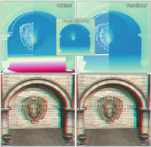
In the simplest case of a single triangle and a target disparity map, we want to render a stereo image pair that renders the triangle according to the map. We do this by sampling the disparity map at each projected vertex position. We then render the triangle from the middle-view camera once for each view, and add an offset to the viewport-space position in opposite horizontal directions for each view. This added offset corresponds to half of the disparity value assigned to the vertex being processed. Consequently, disparity values are respected precisely at the vertices, and are a linear interpolation of the vertex disparities at all other locations. Therefore, as described, this method cannot correctly follow non-linear disparity gradients inside the triangle that may be present in the target disparity map. In order to overcome this limitation, we can apply tessellation to the original triangle before projecting the disparity values to the vertices, resulting in a piecewise linear approximation of the original disparity map.
This procedure can be applied to a complete 3D scene to create a stereo image pair that correctly handles dis-occlusions. We use the hardware tessellation capabilities of modern GPUs to avoid any modifications to the original mesh. However, the disparity re-projection step needs to carefully handle the cases of vertices that are occluded or fall outside the middle-view camera field of view. Figure 5 shows the poor approximation of the target disparity for parts of a scene with low triangle count, such as large flat walls, and the improvement achieved when applying tessellation.
3.4.2. Disparity re-projection
For visible vertices, we can directly assign a disparity value by sampling the disparity map. In order to determine vertex visibility, we compare its projected depth to the depth map created during the initial disparity map creation. Instead of relying only on the corresponding disparity map pixel to which each vertex projects, we sample a small neighbourhood of pixels to increase robustness. This step also allows us to assign a disparity for vertices just outside the view frustum or close to the occlusion boundary. To integrate the result of the samples, we make use of a cross bilateral filter[ED04, PSA*04], using filter weights based on screen-space position, depth difference, normal orientation and object id[TM98]. In this way, samples not related to the current vertex will be discarded automatically. Furthermore, filtering values avoids sudden disparity jumps and improves temporal coherency.
If we cannot determine any valid sample for a vertex, we can still estimate its disparity by comparing D to  at this location and applying the difference to the original disparity of the vertex.
3.5. Implementation details
We initially render the middle view via a deferred rendering pass, outputting several textures that contain properties used in the optimization pass, such as depth information, normals, object id and an initial disparity value. The optimization pass is then performed as a series of compute shader dispatches that create the target gradients, and is followed by a multi-resolution solver [BFGS03] that acts as outlined in Section 3.3, and outputs an optimized disparity texture. Using 16-bit floating point values provides sufficient precision for the optimization procedure and leads to real-time rates. Therefore, an artist can interactively edit the scene, and receive instant feedback.
The final rendering pass uses the optimized disparity map to determine vertex disparities during the tessellation evaluation stage, with the tessellation level determined by screen-space area. The disparity value is then added to the vertex viewport x coordinate in a geometry shader, which is invoked twice with multi-viewport support to efficiently generate a side-by-side image pair.
3.5.1. Optimizing texture resolution
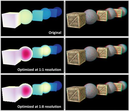
The use of cross bilateral filtering to obtain a per vertex disparity lifts the strict correspondence in terms of resolution for the optimized disparity map and the final image. In our experiments, the optimization resolution can be much lower than the final stereo image resolution without a noticeable difference in quality. Thus, we can target very large stereo image resolutions, while maintaining low memory usage and real-time performance. Figure 6 illustrates the result and stereo images using a 1:1 and 1:8 scale between optimized disparity and final image pair. Moreover, this performance gain can be invested into placing the middle view differently and increasing its field-of-view projection to encompass both views to well handle the screen borders.
3.5.2. Optimizing convergence
In most optimization techniques, and ours in particular, a good initial estimate of the solution results in a faster solver convergence. During the course of a typical animation, the resulting disparity maps will be similar from one frame to the next, which implies that a previous frame is a good estimate of the next frame disparity. Using our re-projection technique, we can create a view for the current frame using the previous disparity values and use it as an initial solution for the optimization procedure.
4. Results
We implemented our method into a tool where a user can easily edit depth content in a scene by accessing the stereoscopic properties described in Section 3. We tested our method for different scenes and with varied artistic purposes to show the range of stereographic modifications that can be easily performed. In the following, we will detail some examples. Figures 1, 6 and 11 showcase scenes were elements are highlighted by increasing their roundness or offsetting them in depth, making them more prominent while still harmonizing with the rest of the scene elements. To illustrate the interaction on an example, in the fairy scene, the user simply clicked on both trees in the background and increased their roundness by a factor of around five. The arising conflicts, that are very visible in the image that directly integrates the indications, were fully removed automatically by our algorithm, while maintaining the overall consistency of the scene. In Figure 4, we show an example of matching the disparity of two characters which are at different depths. This is a useful application in practice since it means an observer does not need to adjust their vergence when switching their gaze from one character to the other. Such quick vergence shifts are known to cause discomfort, and stereographers usually employ various methodologies to avoid them [TDM*14] or in some cases may need to redesign a scene [Men12]. In this case, a user created a matching point constraint between the two characters. As is visible in the result, local contrasts are maintained. This property gives the illusion of maintaining the original scene arrangement, while the disparity of the two characters is actually matched despite them being in different 3D locations in the scene.



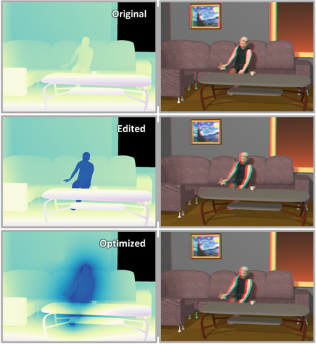
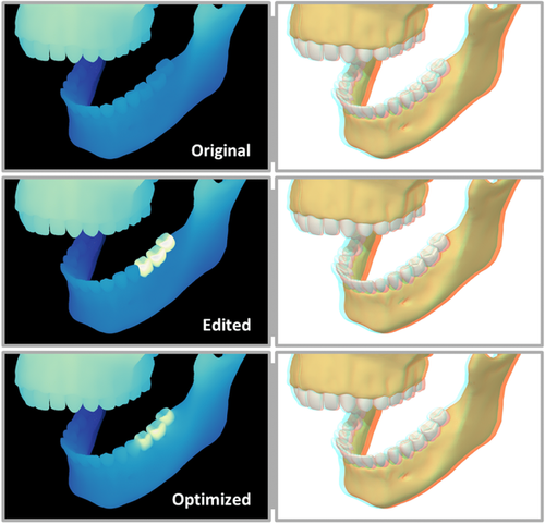
Edits are sometimes useful to evoke emotions. We show an example of a disparity manipulation meant to increase the feeling of scale in Figure 10, by making the cliffs seem more prominent and dangerous. In this case, the user selected parts of the mountain and increased their roundness, while anchoring them at a preferred depth. Additionally, as illustrated in the Supporting Information (videos ), the constraints can be dampened depending on the view of the camera. During the course of animation, the weight of the user's constraints were linked to the camera location, which made them vanish, when the camera rotated away from the cliffs. Another example to convey emotion is shown in Figure 8, where depth edits were used to convey a feeling of loneliness in the scene by flattening the character and pushing him away from the viewer. Hereby, a feeling of distance is created. The editing operation moved the person backwards, which created a conflict with the couch, but also the bunny in his hand. The optimization process adjusts the disparity to correct for these mistakes. As shown, this solution is robust and also handles smaller objects, such as the bunny. Finally, we also believe our method is useful beyond artistic purposes. In Figure 9, we show a visualization of a human jaw, where we want to enhance the shape of the three lower left molars. Such a solution is useful in an educational context to focus attention to important elements. The user only manipulated the roundness to increase the shape perception.
All edits in these scenes required less than a few seconds of interaction. By default object interfaces are maintained, which causes the optimization process to spread the deviation induced by the constraints over all objects. In general, the user input can be very sparse, which supports our goal of simplifying interaction and having the artist focus only on important indications. Additional examples and animations are presented in the accompanying material.
4.1. Memory usage
Memory consumption is almost entirely linked to the textures used for the optimization. It includes the deferred buffers containing the scene properties, and a series of mipmapped textures used for the multi-grid optimization procedure. At full HD resolution, around 160 MB are used, which is directly linked to the disparity map resolution, that is at half that resolution, the memory usage is four times smaller.
4.2. Timing
Our pipeline is implemented using C++ and OpenGL and all tests were run on an Intel i7-5820K CPU running Windows 7, with 32 GB of main system memory and an NVidia Titan X GPU.
Our method employs three stages: the disparity map and scene property extraction, the optimization, and the stereo pair rendering. Three parameters affect the efficiency of these stages: the disparity map resolution  , the final stereo image pair resolution
  and the geometric complexity of the scene G. The first stage is only dependent on
  and G, the second stage depends solely on
  and the final stage is only affected by
  and G. The optimization stage can also be affected by the amount of matching point constraints set by the artist as they render the linear system less sparse and requires additional texture lookups. Out of these parameters,
  is the one an artist has most control over, and can be selected to obtain a desired time/quality balance.
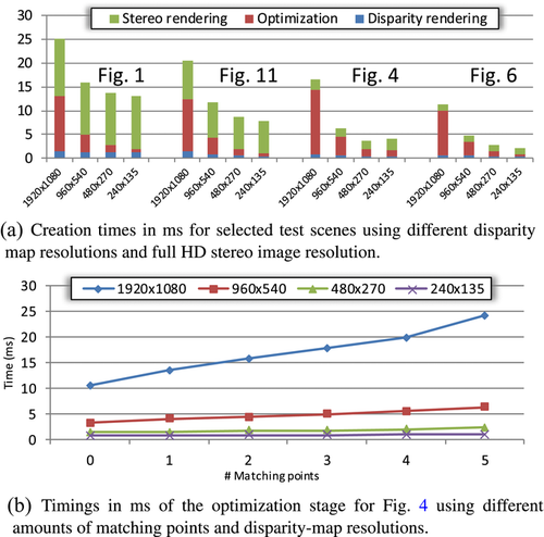
Figure 7(a) showcases the timing of the three stages in some of our test scenes for different resolutions of the optimized disparity map. The optimization procedure is most heavily affected by different matching points and the scene from Figure 4 shows an increased time spent on the optimization procedure. Figure 7(b) shows the effect of different amount of matching point constraints on the optimization timing.


4.3. User studies
4.3.1. Stereo perception study
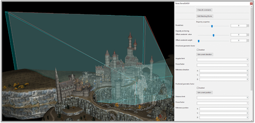
We performed a small-scale user study to evaluate the effectiveness of the stereographic images created through our algorithm. For this, we presented the different versions of the stereo output of Figure 10 to a sample of seven participants, before first verifying that they were able to perceive stereoscopic content. Figure 12 showcases the view frustum and some of the parameters used for this task. All participants had normal or corrected-to-normal vision and no knowledge in the field of stereoscopic content creation or editing.


In the first part of the trial, the participants were shown the original stereoscopic image and our optimized version, and they were freely able to switch between both versions with no time constraints. They were asked to explain the difference between both images and recorded whether they were correctly able to identify the expected edition effect, namely that the cliffs look rounder and more prominent. All participants noticed that the difference between both images were constrained to the cliff area, and five out of the seven (71.5%) described the effect stating that the cliffs were better defined and there was better depth perception in their area.
In the second part, we allowed the participants to observe both our optimized version and the un-optimized edited version, and again they could switch between both images. No time constraint was imposed and they were asked to choose their preferred image. In this case, 100% of the participants expressed a preference for the optimized version, alleging either discomfort or visible artefacts when looking at the un-optimized version.
4.3.2. Usage study
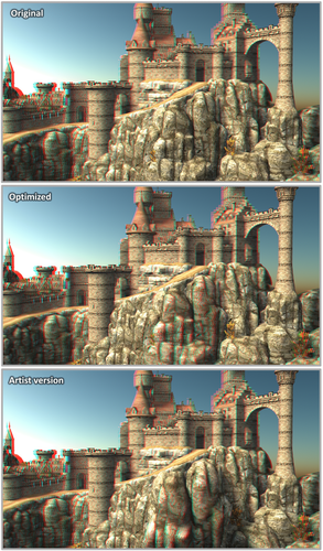
In order to test our solution against a traditional 3D modelling approach, we tasked an expert 3D modeler to create a similar modification as was created with our method in Figure 13, namely to enhance the disparity of two rock models in the scene. The task was performed in Autodesk Maya and the artist reported that around 45 min of work were required. The results are shown at the bottom of Figure 13. The same edition was done in 1 min with our framework. The artist mentioned difficulties to correctly maintain the geometric interfaces between the mesh parts intended to be enhanced and the rest of the scene. Additionally, when asked if the effect could be enhanced, he reported that he would have to basically start over. He also underlined that he considers the task as very challenging. The final image shows a large depth enhancement for the target regions, but as expected, the geometrical shape of the area has been significantly altered. Furthermore, some objects are missing, such as one of the trees. This highlights a key feature in our proposed solution: the ability to largely decouple disparity edition from geometrical shape, thus altering only depth perception while maintaining the geometrical shape of the scene.

4.4. Limitations and future work
We obtain good results for realistic use cases. When introducing highly contradictory constraints, our optimization technique might create artefacts in image sequences. In such cases, adjusting the constraint weights can achieve good results. A limitation exists for thin geometry, and large disparity changes. A large disparity gradient can result in a stretched version of the object to fulfill the indicated disparity constraints. We do not explicitly tackle the problem of temporal stability for image sequences, but as seen in the videos provided with the Supporting Information, the produced disparity values do not show stability problems, as the optimization procedure has a well-defined behaviour and provides a smooth fit to the artist's constraints. If the constraint changes are smooth, the result is typically smooth. We could envision re-projecting the optimized disparity map between consecutive frames using optical flow and rely on equalizing constraints with a small weight to avoid large changes but found it unnecessary in practice.
5. Conclusion
We have presented a method for editing stereoscopic content in 3D scenes by modifying high-level properties of the scene elements. Our approach then identifies regions where depth conflicts may arise from the user input and creates and performs an optimization procedure to obtain a conflict-free disparity map. Although image-based, coupling the map to our re-projection leads to a hole-free stereoscopic image pair. The solution runs fully on the GPU, which leads to instant feedback even for very large image resolutions. Our approach is an important addition to the toolbox of stereographers that simplifies dealing with the various conflicts. It allows the artist to focus on semantics instead of the technical underpinnings and delivers convincing results even when used by novice users.
Acknowledgements
The fairy scene is provided by the University of Utah, Epic Citadel by Epic Games, and Sponza by Marko Dabrovic. The remaining scenes were courtesy of blendswap/archive3D users ChameleonScales, hilux, TiZeta and Rahman Jr. This work is partly supported by VIDI NextView, funded by NWO Vernieuwingsimpuls.


