Generalized moveout approximation for P–SV converted waves in vertically inhomogeneous transversely isotropic media with a vertical symmetry axis
ABSTRACT
We present an overall description of moveout formulas of P–SV converted waves in vertically inhomogeneous transversely isotropic media with a vertical symmetry axis by using the generalized moveout approximation. The term “generalized” means that this approximation can be reduced to some existing approximations by specific selections of parameters, which provides flexibility in application depending on objectives. The generalized moveout approximation is separately expressed in the phase and group domains. All five parameters of the group domain (or phase domain) generalized moveout approximation are determined using the zero offset (or horizontal slowness) ray and an additional nonzero offset (or horizontal slowness) ray. We discuss the selection of parameters to link the generalized moveout approximation to some existing approximations. The approximations presented are tested on homogeneous, factorized, and layered transversely isotropic models. The results illustrate that utilizing an additional reference ray significantly improves the accuracy of phase-domain and group-domain moveout approximations for a large range of horizontal slownesses and source–receiver offsets.
INTRODUCTION
The anisotropic aspect of seismic modelling and processing is now widely taken into account in applied seismology. Transverse isotropy is often observed in sedimentary rocks at long seismic wavelengths. Thomsen's (1986) notation is helpful to characterize transversely isotropic media with a vertical symmetry axis (VTI).
The interest in inverting for the vertical velocity of SV-waves and Thomsen parameters from surface seismic data in VTI media increases with the development of multi-component seismic processing and imaging in shale reservoirs (e.g., Thomsen 1999; Grechka et al. 2002; Cai and Tsvankin 2013). If we use only P-wave surface data, however, it is known that the SV-wave velocity cannot be estimated because the P-wave anisotropic velocity is insensitive to the vertical velocity of SV-waves (e.g., Alkhalifah 1997; Tsvankin and Thomsen 1994). In P-wave velocity analysis, only two-way zero-offset travel time, normal moveout (NMO) velocity, and the anellipticity parameter can be estimated. Compared with P-wave data, converted wave data carry more information. The P–SV converted wave is often observed in surface multi-component data from VTI media, where the term “P–SV” implies a particular conversion: a downward-propagating P-wave, converting on reflection at its deepest point of penetration to an upward-propagating SV-wave (e.g., Stewart et al. 2002; Thomsen 1999).
Theoretically, vertical velocities of P- and SV-waves and Thomsen's parameters (including ε and δ) can be inverted by combining the velocity analysis of P-waves and P–SV-waves and the generalized Dix formulas (Ursin and Stovas 2005; Haugen, Ursin, and Tovas 2007). The velocity analysis based on moveout approximations of P–SV-waves can help provide an NMO velocity model, for the next step of processing seismic data, such as Dix inversion, NMO correction, and Kirchhoff time migration. The velocity analysis of reflection data is performed in the travel-time–offset (t-x) domain (we call it the group domain for simplicity) (e.g., Alkhalifah and Tsvankin 1995; Alkhalifah 1997; Stewart et al. 2002; Thomsen 1999; Alkhalifah 2011; Waheed et al. 2013) or in the travel-time intercept-horizontal slowness (τ-p) domain (we call it the phase domain for simplicity) (e.g., van der Bann and Kendall 2002, 2003; Diebold and Stoffa 1981; Masoomzadeh et al. 2012; Sen and Mukherjee 2003). Despite the limitation of the velocity analysis based on the horizontal layering assumption, the interval parameters estimated from P- and P–SV-wave moveout by means of the Dix equation (Ursin and Stovas 2005) may be implemented as initial models for velocity-independent layer stripping (Dewangan and Tsvankin 2006; Tsvankin 2001; Wang and Tsvankin 2009) and reflection tomography (Foss, Ursin, and de Hoop 2005; Wang and Tsvankin 2013).
Analytic moveout formulas play a prominent role in velocity analysis. For flat-lying VTI layers, the P–SV-wave travel time of P–SV converted waves is an even function of the source–receiver offset in the group domain or of the horizontal slowness in the phase domain. Since the P–SV-wave moveout of P–SV converted waves is inherently non-hyperbolic even for a horizontal isotropic layer, non-hyperbolic moveout approximations are desirable for P–SV-wave velocity analysis. For P–SV-waves in the group domain (t-x), the rational approximation (e.g., Tsvankin and Thomsen 1994; Thomsen 1999; Li and Yuan 2003) matches the four-order moveout expansions at zero offset, and the asymptotic moveout expansions at the infinite source–receiver offset. To enhance the accuracy of rational approximation around the zero-offset ray, the sixth-order term of the P–SV-wave moveout expansion can also be introduced (Ursin and Stovas 2006). The corresponding phase-domain mirror approximation can be obtained from the group-domain approximation. An example of the phase-domain moveout approximation for P-waves in VTI media is shown in Stovas and Fomel (2012a, b).
For many P-wave moveout approximations, some authors (Zhang and Uren 2001; van der Baan and Kendall 2002; Stovas and Ursin 2004; Douma and Calvert 2006) noted the limited accuracy at large offsets. It is possible that the moveout approximations mentioned earlier become inaccurate at large offsets (horizontal slowness). To overcome this disadvantage, in addition to the zero-offset ray, three reference rays with finite offsets are introduced by Douma and Calvert (2006) to form the [2/2] Pade approximation for P-wave moveout in VTI media. Their approximation illustrates the improvement of accuracy within the range between selected rays. As an alternative, the generalized moveout approximation is proposed by Fomel and Stovas (2010), Stovas (2010a), and Stovas and Fomel (2012a). The term “generalized” means that their approximation may be reduced to many existing approximations under some particular assumptions for the selection of parameters. The generalized approximation provides a possibility for an overall description of moveout approximations. The generalized moveout approximation in the group domain includes five independent parameters, three of which are determined from the moveout expansion at the zero-offset ray and others of which are obtained from the travel time and its first-order derivative for a selected non-zero source–receiver offset reference ray. It is reasonably believed that the accuracy of the moveout approximation can be improved within the offset range between the zero-offset ray and the selected finite-offset ray. For the generalized moveout approximation in the phase-domain, all five independent parameters can be specified by a similar procedure.
In this study, we revisit the generalized moveout approximation and apply it to P–SV-waves in VTI media. Under some particular parameter selections, some simple approximations are linked to the generalized moveout approximation. The paper is organized as follows. We start with the generalized moveout approximations for P–SV-waves in the group and phase domains. In the following section, we introduce several other approximations as special cases of the generalized moveout approximation in the group and phase domains. Then, we discuss the estimation of all five parameters in the generalized moveout approximations for homogeneous VTI media, factorized VTI media, and multi-layered VTI media. In the discussion, we explain the application of the generalized moveout approximation in practice.
GENERALIZED MOVEOUT APPROXIMATION
Group-domain generalized moveout approximation
 (1)
(1) and A denote the NMO velocity and the quartic moveout coefficient, respectively; parameters t0,
  , and A are obtained from the following Taylor series:
 (2)
(2) and horizontal slowness
  , i.e.,
 (3)
(3) (4)
(4) (5)
(5) (6)
(6) and
and  are the travel-time intercept and the horizontal slowness from the asymptotic expansion of travel time squared at infinite offset, i.e.,
 (7)
(7)Phase-domain generalized moveout approximation
 (8)
(8) (9)
(9) and A are described after equation 1, and parameters B2 and C2 control the accuracy of the moveout approximation 9 at large horizontal slowness.
 (10)
(10)As an alternative approach, parameters  and A can be specified by matching the Taylor expansion 10 and the corresponding expansion of phase-domain exact travel time squared at the zero horizontal slowness
  .
.
 , where
  denotes the maximum horizontal slowness. We define the travel-time intercept
  and its first-order derivative
  for the selected reference ray. From these operations, it follows that parameters B2 and C2 are obtained, i.e.,
 (11)
(11) (12)
(12) and
and  . It follows that the expressions for B2 and C2 are reduced to
 (13)
(13) (14)
(14)OTHER MOVEOUT APPROXIMATIONS
Fourth-order Taylor approximation
 , the generalized moveout approximation 1 is reduced to the fourth-order Taylor approximation in the group domain, i.e.,
 (17)
(17) (18)
(18)Shifted hyperbola and ellipse approximations
 ,
,  , and
, and  reduces the generalized moveout approximations 1 and 9 to the shifted hyperbola and ellipse approximations in the group and phase domains. The shifted hyperbola approximation is given by
 (19)
(19) (20)
(20)The heterogeneity coefficient s controls the deviation of equation 19 from the hyperbola and the deviation of equation 20 from the ellipse (Stovas and Fomel 2012b).
Rational approximations
 , the generalized moveout approximation 1 is reduced to the rational moveout approximation in the group domain:
 (21)
(21) in generalized moveout approximation 9, i.e.,
 (22)
(22) (23)
(23) and η represent the P-wave NMO velocity and the anellipticity parameter (Alkhalifah and Tsvankin 1995), which can be obtained from the Taylor expansion of P-wave travel time squared at the zero-offset ray.
 (24)
(24)NUMERICAL TESTS
In this section, we apply the generalized moveout approximation to specific models including a homogeneous vertical transverse isotropy (VTI) model, a factorized VTI model, and a multi-layered VTI model. To quantitatively compare the accuracy of the approximations, we slightly modify the two-point P-wave ray tracing algorithm (Tian and Chen 2005; Fowler et al. 2008) to calculate the exact P–SV-wave travel time in the group domain. The exact P–SV-wave travel time in the phase domain can be calculated by using the vertical slowness formulas of P- and SV-waves (van der Baan and Kendall 2003). The following notation is used to describe VTI media: α0 denotes P-wave vertical velocity; r0 denotes the ratio between the vertical S-wave to P-wave velocities; and  and
and  denote the P-wave and SV-wave NMO factors, respectively, where ε and δ are Thomsen (1986) parameters.
A homogeneous VTI model
 , and coefficient A (see Appendix D), i.e.,
 (25)
(25) (26)
(26) (27)
(27)Here,  and
and  given in equation 25 denote P- and SV-wave one-way zero-offset travel times.
To obtain the analytical expression for parameters B1 and C1 given in group-domain generalized moveout approximation 1 and parameters B2 and C2 given in phase-domain generalized moveout approximation 9, we consider the limit case that the incident branch of the selected reference ray becomes horizontal.
 (28)
(28) (29)
(29) (30)
(30) (31)
(31)We design a homogeneous VTI model to test the generalized moveout approximations in the group and phase domains. The model parameters are P-wave vertical velocity  , the ratio between the vertical velocities of SV- and P-waves
  , Thomsen parameters
  and
and  , and the reflector depth
  . The plot (a) in Fig. 1 compares the group-domain generalized moveout approximation with other approximations. This plot shows that the generalized moveout approximation with the horizontal reference ray can produce a satisfactory result, although it has relatively low accuracy at large offset compared with the rational approximation 21 with equation 24; for a selection of the large-offset reference ray, the accuracy of the generalized moveout approximation can be significantly improved. The plot in (b) Fig. 1 shows the relative error of the phase-domain generalized moveout approximation. The relative error in travel time is small enough, which seems that the phase-domain generalized moveout approximation is equivalent to the exact solution.
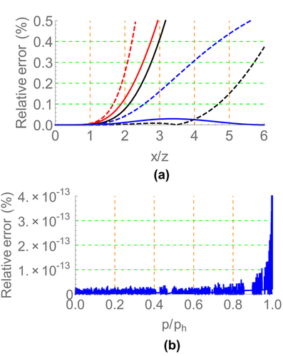
 denotes the ratio of source–receiver offset to reflector depth. The plot (b) illustrates the relative error of the phase-domain generalized moveout approximation 9 with the horizontal reference ray.
  denotes the maximum horizontal slowness of P-waves in this model.
A horizontal reflector in a factorized VTI medium
 (32)
(32) (33)
(33) and
and  denote P- and SV-waves vertical velocities at the depth z, respectively; α0 denote P-wave vertically velocity at surface; H is the thickness of this factorized VTI layer; and
  is the ratio between the vertical velocity of P-wave to the bottom and the vertical velocity to the top of the layer.
 , and coefficient A as follows (see Appendix D):
 (34)
(34) (35)
(35) (36)
(36)By setting  , we obtain equations 25–27. By setting
  , we obtain equations for the linear velocity model (Stovas 2010b).
Parameters B1 and C1 given in the group-domain approximation 1 can be determined by substituting the offset  and travel time
  for the maximum-offset reference ray with the horizontal slowness
  into equations 3 and 4, where the travel time
  and the offset
  are calculated by the parametric equations (D-3) and (D-5) in Appendix D. On the other hand, parameters B2 and C2 given in the phase-domain generalized moveout approximation 9 can be calculated by substituting travel-time intercept
  and its derivative
  for the maximum-offset reference ray with the horizontal slowness
  into equations 11 and 12, where
  is obtained from τ–p transform 8 and
  is obtained by differentiating
  with respect to horizontal slowness P at
  .
.
We use a factorized VTI model to compare the generalized moveout approximations in the group and phase domains with other approximations. The medium parameters are  ,
,  ,
,  ,
,  , and
, and  . The thickness of this horizontal layer is 1 km. Figure 2 shows the relative error of the generalized moveout approximations and other approximations. The plot (a) in Fig. 2 illustrates that the group-domain generalized moveout approximation is almost close to the exact solution, and its maximum relative error is less than 0.02%. The reflected P–SV-wave with the maximum offset is taken as the non-zero offset reference ray for the group generalized moveout approximation. This corresponds to selecting the maximum horizontal slowness of reflected P–SV-waves for the phase-domain generalized moveout approximation. The plot (b) in Fig. 2 shows that the phase-domain generalized moveout approximation also produces a relatively accurate result compared with other approximations, especially at very large horizontal slowness. Except the generalized moveout approximation, we note that the accuracy of other phase-domain approximations decreases rapidly when the horizontal slowness of P–SV-waves approaches its maximum value.
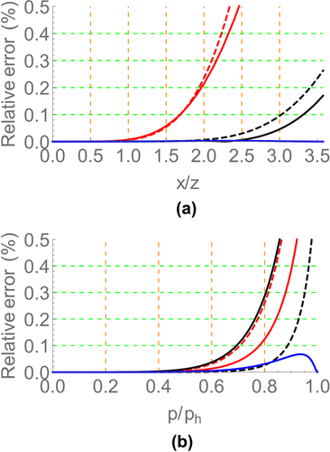
 . The plot (b) illustrates the relative error of the phase-domain approximations versus the normalized horizontal slowness
  , which includes fourth-order Taylor approximation 18 (red line), shifted-hyperbola approximation 20 (red dashed line), rational approximation 22 with equation 23 (black line), rational approximation 22 with equation 24 (black dashed line), and the generalized moveout approximation 1 with the normalized horizontal slowness of the reference ray (blue line) equal to 0.99.
  denotes the maximum horizontal slowness of P-waves in this model.
Multi-layered VTI model
 (37)
(37) (38)
(38) (39)
(39)Here,  ,
,  , are calculated from equations (E-4)–(E-7) in Appendix E.
For the group-domain generalized moveout approximation 1, a finite-offset reference ray is selected to determine parameters B1 and C1 from equations 3 and 4. For the phase-domain generalized moveout approximation, parameters B2 and C2 are determined from equations 11 and 12.
A six-layer VTI model is designed to calculate the error of the generalized moveout approximation and other existing approximations in the group and phase domains. The model parameters are listed in Table 1. Figure 3 shows comparisons of the generalized moveout approximation with other approximations for this model. The plot in Fig. 3 shows that the group-domain generalized moveout approximation may provide a satisfactory accuracy for multi-layered media by using the large-offset reference ray. For the phase-domain generalized moveout approximation in the right plot of Fig. 3, we select the reference ray with the normalized horizontal slowness equal to 0.99. This means that the selected ray is very close to the horizontal ray. Similar to the previous example of a factorized VTI medium, the phase-domain generalized moveout approximation produces accurate results by comparing with other approximations.
 denotes the layer thickness; α0 and β0 are the vertical velocities of P- and SV-waves, respectively; and ε and δ are Thomsen (1986) parameters. The values of these parameters are taken from Ursin and Stovas (2006)
| Layer |
 (km) (km) |
α0(km/s) | β0(km/s) | ε | δ |
|---|---|---|---|---|---|
| 1 | 0.25 | 1.74 | 0.39 | 0.08 | 0.05 |
| 2 | 0.15 | 1.85 | 0.62 | 0.14 | 0.10 |
| 3 | 0.10 | 1.94 | 0.78 | 0.10 | 0.03 |
| 4 | 0.16 | 2.14 | 0.86 | 0.14 | −0.02 |
| 5 | 0.14 | 2.22 | 0.89 | 0.10 | −0.05 |
| 6 | 0.20 | 2.00 | 1.00 | 0.14 | 0.10 |
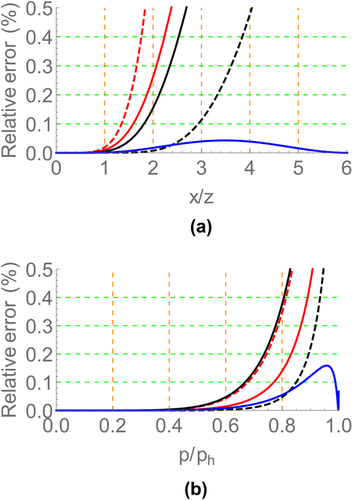
 . The plot (b) illustrates the relative error of the phase-domain approximations versus the normalized horizontal slowness
  , which includes fourth-order Taylor approximation 18 (red line), shifted-hyperbola approximation 20 (red dashed line), rational approximation 22 with equation 23 (black line), rational approximation 22 with equation 24 (black dashed line), and the generalized moveout approximation 1 with the maximum horizontal slowness reference ray (blue line). In the plot (b),
  denotes the maximum horizontal slowness of P-waves in this model.
DISCUSSION
To apply the group-domain generalized moveout approximation in velocity analysis, we select a reference ray corresponding to a large source–receiver offset along a specific seismic event in a common midpoint (CMP) gather. This may be accomplished when the signal-to-noise ratio of seismic data is high. The local slope of the travel-time–offset curve for the selected ray may be automatically estimated for example using the plane-wave deconstruction approach (e.g., Fomel 2002; Schleicher et al. 2009). In the generalized moveout approximation 1 with equations 3 and 4, only zero-offset travel time, NMO velocity, and the quartic moveout coefficients remain unknown. The three quantities can be estimated by the double semblance scanning (e.g., Li and Yuan 2003). From the accuracy analysis in the section of “Numerical examples,” it is reasonable to believe that the estimated NMO velocity and the quartic moveout coefficients are accurate enough for the normal moveout correction in horizontally vertical transverse isotropy (VTI) layers. When using the generalized moveout approximation to do the NMO correction of the CMP data, the effect of stretching of data may be reduced since a long-offset reference ray is involved to constrain the generalized moveout approximation. A similar phenomenon is noted by Douma and Calvert (2006), who used four pairs of travel time and offset of rays to build an accurate rational moveout approximation and found that their approximation can reduce the stretching of long offset data during NMO correction. In practice, it is obvious that the accuracy of the generalized moveout approximation is limited by the accuracy of the travel time and the slope of the selected reference ray. When the quality of the CMP data is too low to select the long-offset ray, the selection of a nonzero-offset reference ray does not help moveout approximation very much. For this case, therefore, the generalized moveout approximation needs to be replaced by relatively simple moveout approximations (e.g., rational approximation or shifted hyperbola approximation) in velocity analysis.
The phase-domain velocity analysis may be done in a similar way. For the phase-domain generalized moveout approximation, we emphasize that the horizontal slowness of the selected reference ray must be close to the maximum horizontal slowness. The maximum horizontal slowness corresponds to the intersection of two phase-domain seismic travel-time curves coming from the upper and lower interfaces of a horizontal layer. The third numerical example in the previous section shows that, for horizontally layered VTI media, all phase-domain approximations, except the generalized moveout approximation, suffer the problem of rapid increase in error when the horizontal slowness tends to the maximum. This indicates that the generalized moveout approximation helps reduce “data stretching” during the phase-domain NMO correction. On the other hand, the “layer stripping” velocity analysis is easier in the phase domain than in the group domain since the horizontal slowness of a considered ray is preserved when passing through horizontal layers. The first numerical example in the previous section shows that when selecting the reference ray with the maximum horizontal slowness, the phase-domain generalized moveout approximation is equivalent to the exact solution. It means that the phase-domain generalized moveout approximation can be used to invert medium parameters for a single horizontal VTI layer without any loss of accuracy. For horizontally VTI media, this approximation may be used in the layer-stripping approach.
To further obtain the interval vertical velocities and Thomsen parameters, NMO velocities and quartic moveout coefficients of pure P-waves and P–SV-waves are combined by the generalized Dix-type formula for VTI media (Ursin and Stovas 2005). This is based on the assumption that both P-waves and P–SV-waves penetrate the same depth.
CONCLUSIONS
The generalized moveout approximation is presented in the phase and group domains. The generalized moveout approximation uses five parameters to describe travel times of P–SV converted waves in vertically inhomogeneous VTI media. A few relatively simple approximations are derived from the generalized moveout approximation by certain selections of parameters. The accuracy comparison with other existing approximations for VTI models shows that the generalized moveout approximation can replace the exact solution to provide accurate travel times of P–SV converted waves within a wide range of source–receiver offsets and horizontal slownesses for horizontally layered VTI media.
ACKNOWLEDGEMENTS
The authors would like to thank the Rock and Seismic (ROSE) Project for financial support, the anonymous reviewer for many valuable suggestions, and Associate Editor Tariq Alkhalifah for his constructive review on this paper.
APPENDIX A: PARAMETRIC EQUATIONS FOR THE P–SV-WAVE TRAVEL TIME IN A HOMOGENEOUS VTI LAYER
In a homogeneous vertical transverse isotropy (VTI) medium, P- and SV-waves can be characterized by the vertical velocities α0 and β0 for P- and SV-waves and two Thomsen (1986) parameters ε and δ. To represent the reflection travel time of P–SV-waves, we adopt Stovas' (2010a) notation of travel-time parameters for P- and SV-waves in a horizontal VTI layer: P-wave vertical velocity α0; the ratio between vertical SV- and P-wave velocities  ; P- and SV-wave one-way vertical travel times
  and
and  with z being the layer thickness; and P- and SV-waves NMO factors
  and
and  .
.
 (A-1)
(A-1) and
and  are given by
 (A-2)
(A-2) (A-3)
(A-3) (A-4)
(A-4) , and
, and  satisfy equation (A-1) and the following equation:
 (A-5)
(A-5) (A-6)
(A-6) (A-7)
(A-7) (A-8)
(A-8) (A-9)
(A-9) (A-10)
 (A-11)
 ,
,  , and
, and  are given by
 (A-12)
 (A-13)
 (A-14)
APPENDIX B: ANALYTICAL EXPRESSIONS FOR B1 AND C1
 (B-1)
(B-1) (B-2)
(B-2) and
and  are determined from the asymptotic expansion of travel time squared at infinite offset, i.e.,
 (B-3)
(B-3) (B-4)
(B-4)Equations (B-3) and (B-4) follow from equation 7.
 given by equation (B-3) denotes the horizontal slowness of the P–SV-wave ray with an infinite offset. Parameter
  is identical to the maximum horizontal slowness
  of P-waves in the VTI medium, i.e.,
 (B-5)
(B-5) (B-6)
(B-6)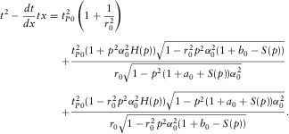 (B-7)
(B-7) given by equation (B-5). From equations (B-4) and (B-7), it follows that the asymptotic traveltime intercept
  is given by
 (B-8)
(B-8) (B-9)
(B-9) (B-10)
 ), equation (B-9) is reduced to
 (B-11)
APPENDIX C: ANALYTICAL EXPRESSIONS FOR B2 AND C2
 (C-1)
(C-1) (C-2)
(C-2) and
and  denote the intercept of travel time and its derivative with respect to the horizontal slowness P for the non-zero offset reference ray, respectively.
 (C-3)
(C-3)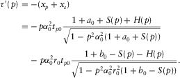 (C-4)
(C-4)In equations (C-3) and (C-4), functions  and
and  are given by equations (A-12)–(A-14) of Appendix A.
 (C-5)
(C-5) (C-6)
(C-6) (C-7)
(C-7) (C-8)
(C-8) ), equations (C-7) and (C-8) are reduced to
 (C-9)
(C-9) (C-10)
APPENDIX D: MOVEOUT COEFFICIENTS FOR P–SV-WAVES IN A FACTORIZED VTI MODEL
 (D-1)
(D-1) (D-2)
(D-2) is the ratio between the vertical P-wave velocity to the bottom and the vertical P-wave to the top of the layer.
 (D-3)
(D-3) (D-4)
(D-4) and
and  are normal moveout factors for the P- and SV-waves, respectively.
 of P–SV-waves, i.e.,
 (D-5)
(D-5) denotes the first-order partial derivative with respect to the horizontal slowness p.
 at the zero-offset ray into a series in terms of the horizontal slowness p, i.e.,
 (D-6)
(D-6) (D-7)
(D-7) (D-8)
(D-8) (D-9)
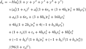
(D-9) is obtained as follows:
 (D-10)
 (D-11)
 (D-12)
 (D-13)
 (D-14)
 (D-15)
 (D-16)
 (D-17)
 (D-18)
 (D-19)
 (D-20)
 (D-21)
 (D-22)
 (D-23)
Note that  ,
,  , in equation (D-23) are given by equations (D-15)–(D-18).
 ), we obtain the corresponding coefficients given by the following:
 (D-24)
 (D-25)
 (D-26)
 (D-27)
APPENDIX E: MOVEOUT COEFFICIENTS FOR P–SV-WAVES IN A MULTI-LAYERED VTI MODEL
 (E-1)
(E-1) denotes the thickness of the ith VTI layer, and
  and
and  denote the vertical slowness of P- and SV-waves in the ith VTI layer. The expressions for
  and
and  are similar to the ones given by equation (A-1).
 (E-2)
(E-2) denotes the first-order partial derivative with respect to the horizontal slowness p.
 , i.e.,
 (E-3)
(E-3) (E-4)
(E-4) (E-5)
(E-5) (E-6)
(E-6) (E-7)
(E-7)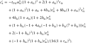 (E-8)
(E-8)Here the subscript “i” denotes the ith VTI layer,  denotes the one-way vertical travel time of P-waves in the ith VTI layer, and
  denotes the P-wave vertical velocity for the ith VTI layer.
  denotes the ratio between vertical velocities of P- and SV-waves for the ith VTI layer, and
  and
and  are NMO factors of P- and SV-waves in the ith VTI layer, where
  and
and  are Thomsen (1986) parameters defined for the ith VTI layer.
 (E-9)
(E-9) , coefficients A and E are given by
 (E-10)
 (E-11)
 (E-12)
 (E-13)
 ,
,  , are given by equations (E-4)–(E-8).


 and
and  . From the limit
  , it follows that equations

