Properties of low-frequency trapped mode in viscous-fluid waveguides
ABSTRACT
We derived the velocity and attenuation of a generalized Stoneley wave being a symmetric trapped mode of a layer filled with a Newtonian fluid and embedded into either a poroelastic or a purely elastic rock. The dispersion relation corresponding to a linearized Navier–Stokes equation in a fracture coupling to either Biot or elasticity equations in the rock via proper boundary conditions was rigorously derived. A cubic equation for wavenumber was found that provides a rather precise analytical approximation of the full dispersion relation, in the frequency range of 10−3 Hz to 103 Hz and for layer width of less than 10 cm and fluid viscosity below 0.1 Pa· s [100 cP]. We compared our results to earlier results addressing viscous fluid in either porous rocks with a rigid matrix or in a purely elastic rock, and our formulae are found to better match the numerical solution, especially regarding attenuation. The computed attenuation was used to demonstrate detectability of fracture tip reflections at wellbore, for a range of fracture lengths and apertures, pulse frequencies, and fluid viscosity.
INTRODUCTION
A physical system described by hyperbolic equations can behave as a waveguide whenever adjacent layers with different properties exist because trapped modes propagating along, but decaying across, the interface are then allowed. Trapped modes satisfy a dispersion relation constraining their wavenumber, or, equivalently, phase velocity and attenuation, to depend on frequency.
The well-known examples in seismic data are a Stoneley wave associated with interface of two different elastic media (Stoneley 1924) and its dispersive analogs: the borehole (Paillet and White 1982) and fracture (Ferrazzini and Aki 1987) Stoneley waves existing when a nonviscous fluid layer is embedded in an elastic rock. The latter were first studied analytically by Krauklis (1962) and later on by Ferrazzini and Aki (1987), which explained the main properties of trapped waves in fluid-filled fractures proposed in Chouet (1986, 1988) as an underlying mechanism for low-frequency tremors accompanying volcanic eruptions. The viscous Newtonian fluid layer case was addressed by Korneev (2008, 2010) for elastic rock. Also, in the work of Dvorkin, Mavko, and Nur (1992), the case of porous rock with a rigid matrix was considered.
In this paper, we consider the most general case of a viscous Newtonian fluid-filled layer embedded into either elastic or poroelastic rock. We first derive the full dispersion relation for the symmetric mode and then find, in a low-frequency regime, its simple algebraic approximation as a cubic equation on the complex valued wavenumber. The latter equation turns out to be a simple tool for calculating phase velocity and attenuation of the trapped mode and can be used in a variety of applications, e.g., in validating feasibility of determining a hydraulic fracture length by registering tip reflections at wellbore. The elastic and poroelastic cases are considered separately.
The derived approximations apply for a wide range of geometrical and dynamical parameters covering frequencies of 10−3 Hz to 103 Hz and layer thickness of less than 10 cm, for diverse rocks and fluids. The approximation quality is checked versus the numerical solution of the full dispersion relation and demonstrated with phase velocity and attenuation curves.
We find that the phase velocity in the poroelastic case is very well approximated by an effective elastic one, and our approximation is only slightly better than the earlier ones (Korneev 2008, 2010). However, the true attenuation in the poroelastic case is much stronger than in the elastic one, starting from a threshold frequency. Thus, our results allow one to compute realistic trapped wave attenuation for poroelastic embeddings, including the case of different fluids in the rock and in the layer.
Knowing that the highly dispersive trapped wave properties may turn out to be important in various studies involving seismic propagation in the presence of subsurface fractures and faults, e.g., fracture width monitoring via borehole tube wave reflections (Hornby et al. 1989; Kostek et al. 1989) or fracture length assessment from tip reflections (Paige et al. 1992; Henry 2005), as well as in subsurface-feature resonance calculations (Chouet 1981; Ferrazini and Aki 1987). In addition, measuring a trapped-mode phase speed and attenuation via subsurface seismic stations proximate to a fault may be an input for the validation of fault properties, including its aperture and the surrounding medium permeability (Nagano and Niitsuma 1996; Korneev, Parra, and Bakulin 2005; Korneev, Bakulin, and Ziatdinov 2006). In reality, no subsurface feature is a perfect slot of a constant aperture; one can reasonably assume, however, that our formulae are applicable asymptotically as long as wavelength is much larger than the asperity and inflection lengthscale.
This paper is organized as follows. In the main text, we start with general problem setting and then show results pertaining to elastic and poroelastic embedding media. In each case, we provide a cubic equation for the trapped-mode wavenumber and represent its solution via phase velocity and inverse quality factor curves. Comparison to earlier results is made whenever applicable. In the conclusion, we discuss the main results and show how they can be used to validate the feasibility of capturing fracture tip reflections from wellbore. Appendices A–D summarize technical information and results, including Biot's, system formulation (Appendix A), potential representation (Appendix B), the dispersion relation (Appendix C), and the low-frequency approximation (Appendix D).
PROBLEM SETTING
An infinite layer, or “a fracture”, of constant thickness h is considered in Cartesian coordinates ( ), where
  are along and z is across the fracture (Fig. 1). The fracture boundaries are at
  and
and  . A fracture is filled with a viscous, Newtonian fluid and embedded in a homogeneous elastic or poroelastic Biot's medium. The external domain (
 ) is a poroelastic Biot's medium. An elastic embedding can be shown to arise as a particular case. We consider z-symmetric and y-independent solutions.

 between the fracture (
 ) and the Biot's medium (
 ) are
) are
 (1)
(1) and
and  are the velocity components of either the elastic matrix or fluid points,
  is the components of Biot's “filtration velocity”,
  and
and  are the components of the full stress tensor, P is the pore pressure, and square brackets denote discontinuity across the interface.
In what follows, we mark the fracture and external half-space quantities by the superscripts 0 and 1, respectively.
Time homogeneity makes it natural to apply Fourier transform with respect to time to dynamic variables. The equations of Biot's model in the frequency representation are recalled in Appendix A.
For a Biot's medium, any dynamic variable, such as particle velocity or the stress tensor, can be represented as a linear combination of spatial derivatives of two scalar potentials φ1, ψ1 and one vector potential  satisfying the Helmholtz equations, as recalled in Appendix B. Thus, the Biot's medium part is rewritten in terms of φ1, ψ1 and A1.
For the fracture part, the linearized Navier–Stokes equations describing propagation of acoustic waves in a Newtonian fluid have the same form as those of an elastic medium if one defines frequency-dependent bulk K and shear G moduli as  and
and  , where ζ0 and μ0 are the moduli of the second (volumetric) and dynamic viscosity, respectively; K0 is the ordinary bulk modulus of the fluid; and ω is the circular frequency. Hence, likewise in the Biot's case above, it is possible similarly to express any dynamic variable via the compressional φ0 and the shear
  potentials satisfying Helmholtz equations, as recalled in Appendix B.
 . Then, the potentials of Biot's medium satisfy 1D differential equations, as it is shown in Appendix C:
 (2)
(2) (3)
(3) (4)
(4) ,
,  , and
, and  are the velocities of the first longitudinal, Biot's (slow) and shear waves, respectively, and k is the wavenumber in x-direction, and
  .
. (5)
(5) (6)
(6) ,
,  ,
,  , and ρ0 is the fluid density. One has
  with great precision within the frequency range
  Hz for viscosity less than 0.1 Pa· s [100 cP].
These simple differential equations are solved in terms of two exponentials with the exponents being linear in z and opposite in sign. Both sign components are kept inside the fracture, although outside, the component growing towards infinity is cut. The latter cut in fact defines the trapped mode.
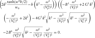
Using the boundary conditions (see equation 1), one obtains a homogeneous system of linear equations for the amplitudes of exponentials, with its consistency condition, or dispersion relation, forcing the determinant depending on k and ω to vanish, as shown in Appendix C. Analytic continuation of this dispersion relation into the complex plane k has a unique solution (wavenumber)  in the frequency range of 10−3 Hz to 103 Hz and for the fracture thickness
  cm, practically for all the rocks and fluids. This solution describes the symmetric low-frequency trapped mode, or “generalized Stoneley wave”, whose phase velocity and non-dimensional attenuation are given by the formulae
  and
and  .
.
The dispersion relation is a complicated transcendent equation; however, at low frequencies, one can simplify it quite a bit by applying appropriate limit assumptions. One can then reduce the system of linear equations to a simpler system whose consistency condition is just a cubic equation for  , as shown in Appendix D. Three roots of the cubic equation can be found by Cardano's formula, and there is a single physical root satisfying
  and
and  and describing the generalized Stoneley wave. Note that the limiting assumptions have been used merely to simplify the original full equations, and their validity has been checked by comparing the resulting approximate solution to the numerical solution of the full dispersion relation, with a very good match as a rule.
Below, for each of the two cases, i.e., an elastic and poroelastic Biot's medium, we list the limit assumptions, provide the cubic equations for  , and check the approximation quality against the precise numerical solution of the full dispersion relation and against earlier approximations by other authors. We also compare the poroelastic case results to the elastic ones, assuming the elastic moduli are the zero frequency limit of poroelastic ones; there is a good match for phase velocity, whereas the poroelastic attenuation is much stronger starting from some threshold frequency.
ELASTIC MEDIUM CASE
- (i)
 , where
  . This condition is obviously satisfied when Stoneley wavelength is much greater than the fracture thickness h.
 - (ii)
 and
and  . The physical meaning of this inequality is neglecting the tangential displacement in a fracture and the tangential stress in an elastic medium.
 - (iii)
 ,
,  ,
,  , and
, and  , where
 and
and  are the velocities of longitudinal and shear waves in an elastic medium, respectively; K1, G1, and ρ1 are the bulk modulus, the shear modulus and the density of elastic medium, respectively.
 (7)
(7) (8)
(8) (9)
(9)In the next section dealing with a poroelastic external medium, this equation is shown to arise as a limiting case.
 (10)
(10)Another cubic equation was suggested later on by Korneev (2010). We have found the corresponding phase velocities are almost equal to the ones obtained by equation 7, but the attenuations differ considerably. Therefore, we have taken the earlier equation 10 for comparison to our results.
Numerical results. In Fig. 2, we compare Stoneley phase velocity and attenuation from the numerical solution of the full dispersion relation (“exact results”) and the equations 7 and 10. Fluid viscosity η0 is 0.001 Pa· s [1 cP], the frequency range is 10−3 Hz to 103 Hz, and the fracture thicknesses h are 0.1 cm, 1 cm, and 10 cm, with the last one merely to verify applicability of the approximations in a limiting case.

In Fig. 3, analogous results are presented for a much more viscous fluid, i.e.,  Pa· s [100 cP]. In all the cases, the parameters of the fluid are
  =1,500 m/s and
  kg/m3, and the parameters of the elastic medium are
  m/s,
m/s,  m/s and
  kg/m3.

Figures 2 and 3 show that our approximation 7 is generally slightly more precise than equation 10. One difference takes place at high frequencies and wide fractures, where our approach is more precise for velocity and somewhat less precise for attenuation. Another distinction is seen at attenuation plots on the right in each figure. For example, at  Pa· s [1 cP] (Fig. 2),
  cm, and frequency of 10 Hz, our results are more accurate, and this is due to the fact that equation 10 was obtained as a combination of two solutions for
  and
and  .
.
POROELASTIC MEDIUM CASE
- (i)
 , where
  , as in the elastic case.
 - (ii)
 in the fracture and
  in the Biot's medium, as in the elastic case.
 - (iii)
 ,
,  ,
,  and
and  , as in the elastic case.
 - (iv)
 , where
  is Biot's frequency, and ϕ1,
  ,
,  , η1, and
  are the porosity, the tortuosity, the permeability, the viscosity, and the density of the pore fluid, respectively.
 - (v) Biot's wave contribution to
 and
and  is negligible.
 - (vi)
 .
.
 (11)
(11) (12)
(12) (13)
(13) (14)
(14) (15)
(15) (16)
(16)Here  , and
, and  , where
  and G1 are the bulk and shear moduli of the dry matrix,
  is the bulk modulus of matrix material, χ1 is the bulk cementation factor,
  ,
,  is the bulk modulus of the pore fluid.
  is the density of the wet medium, where
  is the density of matrix material,
  and
and  are the velocities of first longitudinal and shear waves at the low-frequency limit (at zero frequency), and
  is the external medium diffusion constant.
The elastic case cubic equation 7 can be obtained as a limit of this one. There are two different limiting procedures, each resulting in its own elastic case.
In the first procedure, one makes the porosity ϕ1 tend to 0, the bulk cementation factor value χ1 tend to 1, and the rock diffusion constant  tend to 0. Then, the parameter
  tends to 0; hence,
  tends to infinity, whereas the term
  is finite since
  and
and  (see equation A.5 in Appendix A). Then,
  and
and  . Using all of the above, one obtains, using equations 12 through 15, the cubic equation 7 with the coefficients 8.
In the second procedure, one makes the mobility  tend to zero; then, the terms of coefficients A0, A1, and A2, which include the diffusion constant
  , also tend to zero. Setting mobility to zero for poroelastic moduli is equivalent to taking the zero-frequency limit. Hence, one obtains, again, the approximate equation 7 for an elastic medium with the elastic moduli derived from their poroelastic analogs with mobility set equal to zero, e.g., the phase velocities are zero-frequency limits of the poroelastic ones.
 (17)
(17) .
.The solutions of this equation will be validated against our ones below.
Numerical results. In Fig. 4, we compare Stoneley phase velocity and attenuation from the numerical solution of the full dispersion relation (“exact results”), our cubic equation solution 11, and the one of equation 17.

We use the Fontainebleau-B sandstone as an example of a high-velocity permeable formation; its parameters are listed in Table 1. The fluid in the fracture has the same velocity and density as the pore fluid. The frequency range is 10−3 Hz to 103 Hz and the fracture thicknesses are 0.1 cm, 1 cm, and 10 cm. The fluid viscosity values are  Pa· s [1 cP]. When the viscosity values of fracture and pore fluids are
  Pa· s [1 cP] and
  Pa· s [100 cP], correspondingly, i.e., differ appreciably, the results are as presented in Fig. 5. In Figs. 4 and 5, the solid curves are solutions of the full dispersion relation, and the dashed curves are those of equation 11.

| Fontainebleau-B sandstone | Idaho sandstone | |
|---|---|---|
| First longitudinal / shear velocity | ||
at zero frequency,  / /  (m/s) (m/s) |
3760 / 2306 | 2707 / 1339 |
| Density, ρ1 (kg/m3) | 2370 | 2181 |
Material bulk modulus,  (Pa) (Pa) |
3.9 × 10¹⁰ | 3.9 × 10¹⁰ |
| Bulk cementation factor, χ1 | 0.28 | 0.14 |
| Shear modulus, G1 (Pa) | 1.26 × 10¹⁰ | 3.91 × 10⁹ |
Material density,  (kg/m3) (kg/m3) |
2650 | 2650 |
| Pore fluid velocity (m/s) | 1500 | 1500 |
Pore fluid density,  (kg/m3) (kg/m3) |
1000 | 1000 |
| Porosity, ϕ1 | 0.17 | 0.28 |
Permeability,  (darcy = (darcy =  m2) m2) |
0.2 | 1.0 |
Tortuosity,  |
3.3 | 2.4 |
 |
1.0 | 1.0 |
Another set of examples, for Idaho sandstone, i.e., a low-velocity and high permeability formation (Table 1), is shown in Figs. 6 and 7.


When  Pa· s [1 cP], the Biot's frequency
  is equal to 41 kHz for the Fontainebleau-B sandstone and 18.6 kHz for the Idaho sandstone. Thus, for all cases
  Hz, the upper frequency of interest, and our assumption (iv) is satisfied.
Figures 4–7 show that our approximation is basically quite accurate, except for high frequencies and wide fractures. In Fig. 6, we have small discrepancies of velocity and attenuation at low frequencies and narrow fracture  cm. This can be attributed to the fact that the Stoneley velocity becomes close to the velocity of the slow Biot's wave, so the assumption (vi) (
 ) is barely violated.
In Fig. 4, the results obtained by equation 17 are given by dash-dotted curves. For brevity, curves for  cm and 1 cm at low frequencies are not shown. One can see our approximation (11) is considerably better.
For all cases  Hz, it is interesting to compare the results versus the elastic case ones, where the dynamic moduli of the elastic counterpart are given by the zero-frequency limit of the poroelastic ones.
In Figs. 4–7, the elastic results are given by dotted curves. In fact, the phase velocities are practically the same for elastic and poroelastic cases, except for wide fractures and low frequencies where the poroelastic formulae are somewhat more accurate.
The situation with attenuations is different, attenuations basically coincide at low frequencies, except for narrow fractures and low frequencies where the poroelastic approximation is also somewhat better. The difference grows with frequency. A threshold frequency increases as the fracture gets thinner and the normalized skin depth  gets larger, and as the rock fluid viscosity η1 grows. One can also see by comparing Figs. 5 and 7 that, below the threshold frequency, the attenuation almost does not depend on the rock fluid viscosity.
Thus, the main value of our formulation for the poroelastic case is a calculation of Stoneley attenuation at higher frequencies typically starting from 1 Hz.
The obtained results can be used to calculate attenuation of the trapped mode along specific propagation distance, e.g., if a hydraulic fracture propagating in a permeable rock is connected to a wellbore and a pressure pulse is generated in the wellbore in front of the fracture inlet, the question is: Would the trapped wave propagating along the fracture towards fracture tip and back to wellbore completely decay or would it be still detectable at wellbore? Let us assume, for calculation convenience, that the wave is detectable if the roundtrip attenuation (wellbore–fracture tip–wellbore) is 100 times. Let us assume the tip reflection coefficient is just 1. Then the pulse decays 10 times as it propagates one way along the fracture. This defines the detectable length of a hydraulic fracture as a function of frequency. The graphs in Figure 8 present the detectable length.

The Biot's formation is the Fontainebleau-B sandstone (see Table 1); the pore fluid viscosity values are  Pa· s, 0.01 Pa· s, and 0.1 Pa· s. The fracture fluid has the same velocity and density as the pore fluid; the fracture fluid viscosity is
  Pa· s. In the left graph in Fig. 8, the fracture thicknesses are fixed and equal to 1 cm, and the frequency range is 10−3 Hz to 103 Hz. In the right graph, on the contrary, the fracture thickness varies from 0.1 cm to 2 cm, and the frequency is fixed and equal to 5 Hz.
One can see, in particular, that length of a hundred meter long, 1-cm-wide water-filled fractures are detectable with a 10-Hz pulse, regardless of the rock fluid viscosity. Lightening the “100 times decay” detectability threshold will naturally increase the range of detectable length.
CONCLUSIONS
We have worked out the case of symmetric low-frequency trapped mode or generalized Stoneley wave in a fracture of constant thickness filled with a viscous Newtonian fluid embedded in either a homogeneous elastic or poroelastic Biot's medium. A full linearized Navier-Stokes equation in the fracture has been coupled to the elastic or Biot's model in the embedding medium, and the associated “dispersion relation” has been derived and approximated by a cubic equation on generalized Stoneley wavenumber, in a low-frequency regime. The physical unique root of this equation has been checked against the numerical solution of the full dispersion relation in several cases and found to provide a good-quality approximation in the frequency range of 10−3 Hz to 103 Hz and for a layer thickness below 10 cm. Our results have been compared to analogous ones proposed by Korneev (2008) for elastic embedding and by Dvorkin et al. (1992) for porous rigid embedding, and they were found to be more precise with respect to the numerical solution of the dispersion relation, especially in regard to attenuation. Also, we have compared our approximations for Biot's and elastic embedding media assuming the latter has the same properties as the porous one with mobility set zero, and we demonstrated that phase velocities match, although attenuations diverge at higher frequencies typically, starting at about 1 Hz. The detectability of fracture tip reflections at the wellbore has been validated and shown to be feasible with a 10-Hz pulse for a 100-m-long water-filled fracture.
APPENDIX A: BIOT'S SYSTEM IN FREQUENCY REPRESENTATION
Biot proposed a theory of acoustic propagation in fluid-filled porous media (Biot 1956a, b; Biot 1962). Then, Johnson, Koplik, and Dashen (1987), based on experimental data, developed the Biot's theory further based on dynamic permeability and tortuosity considerations.
 (i = 1, 2, 3), the Biot's equations in frequency representation, using our notation (Plyushchenkov and Turchaninov 2006), are
 (A.1)
(A.1) (A.2)
(A.2) (A.3)
(A.3) (A.4)
(A.4) is the mean velocity vector of elastic matrix particles;
  is the Biot's “filtration velocity”, where
  is the mean velocity vector of pore fluid and ϕ is the porosity; σ and P are the full stress tensor and the pore pressure, respectively;
  denotes the Kronecker delta-symbol;
 (A.5)
(A.5) and
and  are bulk moduli of pore fluid and frame material;
  and G are the Lame moduli of dry matrix, where
  is the bulk modulus of dry matrix, and
  is the bulk cementation factor;
  is the formation density, where
  and
and  are the density of matrix material and the density of pore fluid, respectively, and
 (A.6)
(A.6) is the the Biot's frequency, κ0 and
  are the limiting value of formation dynamic permeability
  and tortuosity when the circular frequency ω tends to zero and infinity (Johnson et al. 1987), respectively, η is the viscosity of pore fluid, and
  is the additional parameter depending on the pore geometry (Johnson 1989).
APPENDIX B: POTENTIAL REPRESENTATION AND LOW-FREQUENCY APPROXIMATE RELATIONS FOR BIOT'S PARAMETERS
 and
and  , from equations A.1–A.4, one gets the following equations:
 (B.1)
(B.1) (B.2)
(B.2) and
and  can be written as
 (B.3)
(B.3) (B.4)
(B.4) and
and  .
.- (a)
 , where the scalar potentials φ and ψ satisfy the Helmholtz equations:
 (B.5)The potential φ is related to the fast wave that propagates at the compressional wave velocity
 (B.6)
(B.6) . The potential ψ is associated with the slow or Biot's wave, which has the velocity
  . The slow wave propagates basically as a diffusive wave at low frequencies, i.e., at those less than Biot's frequency
  , and as a compressional wave at high frequencies. The quantities
  and
and  are
are
 (B.7)where
 (B.8)
(B.8) .
. - (b)
 , where the quantities γ1 and γ2 are
 (B.9)
(B.9) - (c) The vector potential
 must satisfy the Helmholtz equation:
 (B.10)and
 (B.11)
 is responsible for the shear wave propagating with the velocity
  . The other vector potential is
 (B.12)
 ) has only one nonzero y-component, therefore, the following field components can be presented through the above potentials as
 (B.13)
 (B.14)
 (B.15)
 (B.16)
 (B.17)
 (B.18)
 (B.19)
where  , and
, and  ,
,  .
.
 and
and  , one has
 (B.20)
 (B.21)
 (B.22)
 (B.23)
 ) satisfy the Helmholtz equations and are responsible for the longitudinal and shear waves that propagate at
  and
and  velocities, correspondingly.
The equations B.20–B.23 can be used to describe a viscous Newtonian fluid, if one defines  ,
,  , and
, and  , where ξ and η are the modulus of the second (volumetric) and the shear viscosity, respectively.
At low frequencies, i.e., when  , one can get the approximate expressions for the following Biot's parameters, which will be used in Appendix D.
 (B.24)
 (B.25)
 (B.26)
 (B.27)
APPENDIX C: DISPERSION RELATION
One starts with frequency-domain equations of Appendix B. The particle velocity and the stress tensor are expressed as spatial derivatives of potentials both in the fluid and in the rock.
Assuming the solution is z-symmetric and y-independent, we apply Fourier transform along x parameterizing fracture axis to the equations B.5, (B.6), and (B.10). In the poroelastic medium case, the Fourier-transformed potentials  ,
,  and
and  , marked by subscript F, satisfy 1D differential equations 2– 4. Analogously, in the fracture filled with viscous fluid, the Fourier-transformed potentials
  and
and  satisfy the equations 5 and 6. The superscripts 0 and 1 mark the fracture and external half-space parameters, respectively.
- (a) for
 , i.e., in the fracture, as
 (C.1)
(C.1) - (b) for
 , i.e., in the poroelastic medium, as
where Φ0, A0, Φ1, Ψ1 and A1 are complex valued unknowns.
 (C.2)
(C.2)
- (a) for
 ,
,
 (C.3)
(C.3) - (b) for
 ,
,
 (C.4)
(C.4) - (c) for
 ,
,
 (C.5)
(C.5) - (d) for
 ,
,
 (C.6)
(C.6) - (e) for
 ,
,
 (C.7)
(C.7)
 (C.8)
(C.8) (C.9)
(C.9) with
with  ,
,  ,
,  ,
,  ,
,  ,
,  ,
,  and
and  .
. in C.2, using B.20–B.23 and the continuity conditions
 (C.10)
 (C.11)
 , where
  ,
,  ,
,  ,
,  and
and  .
. (C.12)
 corresponding to the Stoneley mode. At low frequencies and in the physical branch
  ,
,  , the Stoneley mode is the only solution.
APPENDIX D: APPROXIMATE DISPERSION RELATION OF STONELEY WAVE
 ), the assumption (ii) (
 and
and  ) and the assumption (v) (Biot's wave contribution to
  and
and  is negligible, i.e.,
  ,
,  ) yields
 (D.1)
(D.1) (D.2)
(D.2) , and using that
  , as
, as  , we get the approximate equation
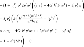 (D.3)
(D.3) ) is valid, one can simplify the following expressions, neglecting the associated small terms:
- (a) Under the assumption (iii) (
 ,
,  , and
, and  ), it follows
 (D.4)
(D.4) (D.5)Then, using expressions B.24, B.25, and B.33, we get
 (D.6)
(D.6)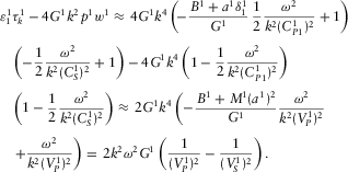 (D.7)
(D.7) - (b) By expression B.25 and inequality B.32, it follows that
Using expressions B.29 and B.31, the approximate expression for the term
 (D.8)
(D.8) is
Substituting D.9 into D.8 and assuming
 (D.9)
(D.9) (see expression B.26), we obtain
Therefore, in general, it is impossible to neglect the term
 (D.10)
 in the expression D.8 in spite of its obviously small value.
 (D.11)
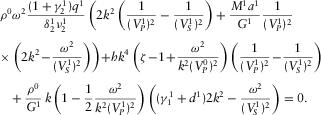 (D.12)
 , after some algebra, neglecting again terms being small under the assumption (iii) (
 ,
,  , and
, and  ) yields
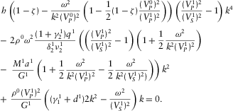 (D.13)
 and
and  , we neglect these terms in the equation D.13 and use, under the assumption (vi) (
 ), the approximation
 (D.14)
 (D.15)
 (D.16)
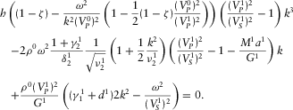
Finally, substituting B.26, B.35, B.36 and D.9 into D.16 and dividing it by the term  , after transformations, we get the final cubic equation 11, which is given in the main text.
 (D.17)
 (D.18)
 , one has
 (D.19)
 (D.20)


 and
and  (see equation
  .
.

 and, generally,
  .
. , one obtains



 ),
),

