Usefulness of entrainment mapping using the activation sequence of the last captured excitation in complex dual-loop atrial tachycardia
Abstract
Background
Electroanatomical mapping is useful for locating the atrial reentrant circuit, but analysis of the dynamic relation of the reentrant circuit is sometimes difficult. This article describes three cases of complex dual-loop reentrant atrial tachycardia analyzed by entrainment mapping using not only the postpacing interval (PPI) but also the activation sequence of the last captured beats.
Methods
Case 1 was dual-loop reentry consisting of the tricuspid annulus (TA) and a localized atrial reentry at the coronary sinus (CS) ostium with different exit sites to the right and the left atrium that was cured by catheter ablation at the CS ostium showing fractionated potential. Case 2 was dual-loop reentry around the TA and the superior trans-septal incision line. Case 3 was dual-loop reentry around the TA and longitudinal dissociation along the cavo-tricuspid isthmus.
Results
In Cases 1 and 2, entrainment with a shorter pacing cycle length demonstrated antidromic penetration to the circuit and changed the activation sequence of the last captured beat depending on the anatomical relation of the reentrant circuit. In Cases 1–3 with dual-loop reentry, the excitation wavefront induced by stimulation entered one circuit after going around the other; thus, the penetration to the other reentry circuit became the second beat after the stimulus (one lap behind).
Conclusions
The PPI is obtained from the pacing site only, but the last captured beat could be obtained from all electrodes. It is advantageous to use the information from all available electrode recordings to determine the dynamic relation between complex dual-loop reentrant circuits.
1 Introduction
Electroanatomical mapping is useful for locating a possible reentrant circuit, but it has limitations in terms of analyzing the functional property of the circuit [1], [2]. Entrainment mapping using the postpacing interval (PPI) and the activation sequence of the last captured beat has been used for analyzing complex reentrant tachycardia circuits [3], [4]. This article describes three cases of complex dual-loop reentrant atrial tachycardia analyzed by conventional entrainment mapping without using a three-dimensional PPI mapping system. Case 1 was dual-loop reentry consisting of the tricuspid annulus (TA) and a localized atrial reentry at the coronary sinus (CS) ostium with different atrial connection sites to the right and left atrium. Case 2 was dual-loop reentry around the TA and the superior trans-septal incision line. Case 3 was dual-loop reentry around the TA and longitudinal dissociation along the cavo-tricuspid isthmus. In these three cases, analysis of the activation sequence of the last captured beat was useful for clarifying the dynamic relation of reentrant circuits.
2 Materials and methods
Electrophysiological study and radiofrequency catheter ablation was performed using standard methods after obtaining written informed consent. Entrainment mapping was performed from several atrial sites during tachycardia at a cycle length of 20–50 ms shorter than the tachycardia cycle length (TCL). A shorter pacing cycle length was selected on purpose to demonstrate the deeper antidromic penetration to the reentrant circuit. The PPI from the pacing site and activation sequence of the last captured excitation from all available electrodes was analyzed to determine the composition of reentrant circuits. The last captured beat was defined as the last activation where the preceding cycle length was the same as the pacing cycle length after the termination of overdrive pacing. A radiofrequency catheter ablation was performed to achieve a target temperature of 55 °C for a maximum power of 30–50 W.
Dual-loop reentry was defined as reentry involving two simultaneously coexisting loops sharing a common pathway of unidirectional activation. Two reentrant circuits may have different TCLs. The reentrant loop having the shorter TCL becomes the dominant circuit, and the remaining reentrant loop with the longer TCL is continuously entrained by the activation wavefront from the dominant circuit.
3 Results
3.1 Case 1: Dual-loop reentry consisting of the TA and a localized reentry at the CS ostium with different exit sites
An 83-year-old man experienced palpitations on effort one month before admission. His twelve-lead ECG showed atrial flutter at a heart rate of 60/min (Fig. 1, upper). He was referred for ablation of atrial flutter. A 20-pole TA catheter with 5-mm inter-electrode spacing was positioned in the right atrium parallel to the TA, and the distal electrode (TA 1–2) was located in the proximal region of the cavo-tricuspid isthmus. Another 10-pole electrode catheter with 5-mm inter-electrode spacing was positioned at the CS.
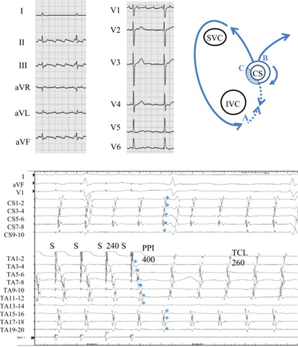
Twelve-lead ECG during atrial tachycardia (upper-left), schema of the tachycardia (upper-right), and entrainment from the cavo-tricuspid isthmus (lower) in Case 1. Upper left: During atrial tachycardia, the saw-tooth pattern of the P wave suggested the common type of atrial flutter. Upper right: Schema of the localized reentry at the coronary sinus (CS) ostium with different exit sites to the right and the left atrium. SVC=superior vena cava, IVC=inferior vena cava. Lower: Simultaneous recordings of surface ECG leads I, aVF, and V1, intracardiac recordings along the tricuspid annulus (TA) from the low lateral right atrium (TA 1–2) to the high right atrium (TA 19–20), and recordings along the CS. During atrial flutter, counter-clockwise conduction around the TA appears. Note that after entrainment from the cavo-tricuspid isthmus, the last captured beats (⁎) at the right atrial septal wall (TA 15–16 to TA 19–20) and at the CS were the second beat after the stimulus. The post-pacing interval (PPI) of 400ms was prolonged compared with the tachycardia cycle length (TCL) of 260ms.
In this patient, the TCL was 260 ms and the CS activation was proximal to distal (Fig. 1, lower). Activation mapping showed counter-clockwise rotation around the TA, suggesting the common type of atrial flutter, although the timing of activation from TA15–16 to TA19–20 was simultaneous. Entrainment from the cavo-tricuspid isthmus at a cycle length of 240 ms induced a long antidromic penetration through the right atrial free wall (TA1–2 to TA13–14) and a prolonged PPI of 400 ms compared with the TCL. The last captured beats (⁎) at the proximal TA (TA 15–16 to 19–20) and at the CS (CS 1–2 to 9–10) were the second beat after the stimulus (Fig. 8A). These findings suggested that the cavo-tricuspid isthmus was not involved in the dominant reentrant circuit.
During entrainment from the CS proximal (CS 7–8) at a cycle length of 240 ms, the last captured beats (⁎) at the TA (TA 3–4 to 19–20) and at the CS distal (CS 1–2 to 5–6) were the second beat after the stimulus (Fig. 2, upper). However, entrainment from the same site at a shorter cycle length of 220 ms changed the response pattern. The last captured beat (⁎) at the TA (TA 3–4 to 19–20) was the second beat after the stimulus and the last captured beat (⁎) at the CS (CS 1–2 to 5–6) became the first beat after the stimulus (Fig. 2, lower). A value of 260 ms and 270 ms for the PPI at the CS proximal suggested that the CS proximal was located on the dominant reentrant circuit.
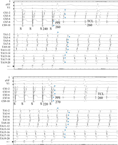
Entrainment from the proximal coronary sinus (CS) in Case 1. Upper: During entrainment at a pacing cycle length of 240ms, the last captured beats (⁎) at the tricuspid annulus (TA) and at the distal CS were the second beat after the stimulus. The postpacing interval (PPI) was 260ms, the same as the tachycardia cycle length (TCL). Lower: During entrainment at a pacing cycle length of 220ms, the last captured beats (⁎) at the CS became the first beat after the stimulus and the PPI was 270ms.
Fractionated potentials were recorded from the 8-mm-tip ablation catheter (ABL 1–2) located at the posterior roof of the CS ostium (Fig. 3, upper). During entrainment with bipolar pacing at this site, the preceding small electrogram before stimulation artifact could be recognized. The stimulus captured the next preceding potential of the fractionated electrogram. Entrainment from the fractionated potential falsely showed a shorter PPI of 240 ms compared with the TCL, but the actual captured potential was the late component of the fractionated electrogram that showed a PPI of 260 ms, the same as the TCL (Fig. 8D). The last captured beats at the TA (TA 1–2 to 19–20) and at the CS (CS 1–2 to 9–10) were the first beat after the stimulus. Radiofrequency energy delivered to this fractionated potential recording site separated the fractionated potential and terminated atrial tachycardia within 10 s (Fig. 3, lower).
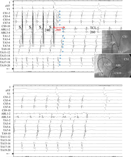
Entrainment from the posterior roof of the coronary sinus (CS) ostium and termination of tachycardia during radiofrequency energy delivery in Case 1. Upper: During entrainment from the posterior roof of the CS ostium showing fractionated potential, the last captured beats (⁎) at the tricuspid annulus (TA) and the CS were the first beat after the stimulus. The schematic mechanism of the preceding small electrogram before the stimulation artifact during entrainment is shown in Fig. 8D. It was difficult to identify the beginning of x potential because both y and x potentials became continuous fractionated electrograms in this case. If we defined x potential as the latest component of the fractionated potential, PPI became 260ms (red arrow). Lower: Radiofrequency energy delivered to this fractionated potential recording site separated the potential and terminated the tachycardia.
3.2 Case 2: Dual-loop reentry around the TA and the superior trans-septal incision line
A 77-year-old woman with mitral valve replacement that had employed the superior trans-septal approach had post-operative atrial flutter (Fig. 4, upper). The TCL was 280 ms. Activation mapping showed counter-clockwise rotation around the TA, and double potentials were observed along the superior trans-septal incision line (TA 9–10 to TA 19–20). Entrainment from the corridor between the superior trans-septal incision line and the TA at a cycle length of 250 ms using an 8-mm-tip ablation catheter demonstrated a prolonged PPI of 340 ms compared with the TCL (Fig. 4, lower). The last captured beat (⁎) along the trans-septal incision line was the first beat after the stimulus (one or both components of the double potentials). The last captured beat (⁎) of the low lateral TA (TA 1–2 to TA 7–8) was the second beat after the stimulus. These findings suggested that the dual-loop reentrant circuits consisted of counter-clockwise rotation of the TA and clockwise rotation around the superior trans-septal incision line (Fig. 8E).
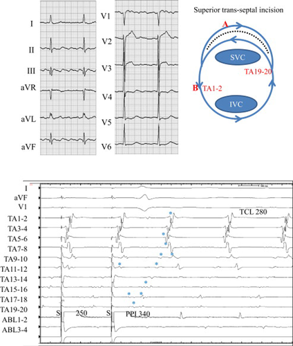
Twelve-lead ECG during atrial tachycardia (upper left), schema of the tachycardia (upper right), and entrainment from the corridor between the tricuspid annulus (TA) and the superior trans-septal incision line (lower) in Case 2. Upper left: During atrial tachycardia, the saw-tooth pattern of the P wave was seen in limb leads. Upper right: Schema of dual-loop reentry consisted of a circuit around the TA and the superior trans-septal incision line (dotted line). SVC=superior vena cava, IVC=inferior vena cava. Lower: Simultaneous recordings of surface ECG leads I, aVF, and V1, intracardiac recordings along the tricuspid annulus (TA) from the low lateral right atrium (TA 1–2) to the right septal (TA 19–20), and the ablation catheter located at the corridor. During AFL, counter-clockwise (CCW) conduction around the TA appears. Note that after entrainment from the corridor, the last captured beats (⁎) at the right atrial free wall (TA 5–6 to TA 1–2) were the second beat after the stimulus. The post-pacing interval (PPI) of 340ms was prolonged compared with the tachycardia cycle length (TCL) of 280ms.
Entrainment from the lower lateral TA (TA 1–2) at a cycle length of 250 ms demonstrated a PPI of 285 ms, which is close to the TCL (Fig. 5, upper). The last captured beats (⁎) from the CS ostium (ABL) to TA 9–10 around the TA were the first beat after the stimulus, and the late components of the double potentials along the trans-septal incision line (from TA 5–6 to TA 15–16) were the second beat after the stimulus. The return cycle of TA 3–4 (Fig. 5, upper, #) was 260 ms shorter than the TCL, suggesting the antidromic capture (Fig. 5, upper, ⁎⁎) of this site during entrainment (Fig. 8F).
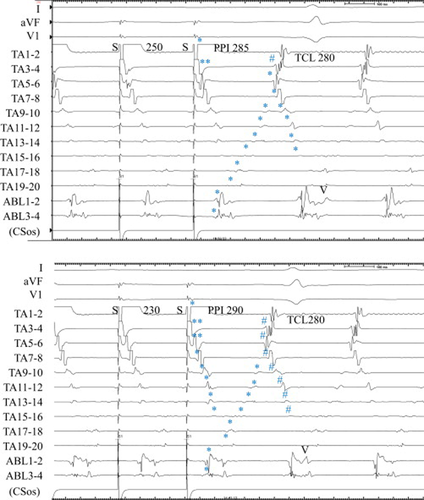
Entrainment from the low lateral right atrium in Case 2. Upper: During entrainment at a pacing cycle length of 250ms, the last captured beats (⁎) at the corridor between the tricuspid annulus (TA) and the superior trans-septal incision was the second beat after the stimulus. The postpacing interval (PPI) was 285ms, which was close to the tachycardia cycle length (TCL). Lower: During entrainment at a pacing cycle length of 230ms, the last captured beats (⁎) at the corridor became the first beat after the stimulus and the PPI was 290ms. #=shorter return cycle than TCL, ⁎⁎=antidromic capture.
Entrainment from the same lower lateral TA (TA 1–2) at a shorter cycle length of 230 ms revealed a PPI of 290 ms (Fig. 5, lower). The last captured beats (⁎) from the CS ostium (ABL) to TA9–10 around the TA were the first beat after the stimulus, the same as in a cycle length of 250 ms. However, the last captured beat (⁎) of the late component of the double potentials along the superior trans-septal incision became the first beat after the stimulus. TA 3–4 and TA 5–6 were captured in the antidromic direction (Fig. 5, lower, ⁎⁎). The return cycle of TA 3–4 and TA 5–6 became shorter than the TCL (Fig. 5, lower, #). The activation sequence along the superior trans-septal incision was orthodromic, but the return cycle became less than the TCL (Fig. 5, lower, #) (Fig. 8G). Radiofrequency energy delivery to the cavo-tricuspid isthmus induced atrial fibrillation. Further ablation to the isthmus around the trans-septal incision line was rejected.
3.3 Case 3: Dual-loop reentry around the TA and the longitudinal dissociation along the cavo-tricuspid isthmus
A 52-year-old man with repaired tetralogy of Fallot was referred for catheter ablation of atrial flutter. A 20-pole TA catheter with 5-mm inter-electrode spacing was positioned in the right atrium parallel to the TA, and the distal electrodes (TA 1–2 and TA 3–4) were located within the CS ostium. The TCL was 320 ms. Activation mapping showed counter-clockwise rotation around the TA, and cavo-tricuspid isthmus ablation was started during atrial flutter. Radiofrequency energy delivered to the lateral isthmus suddenly shortened TCL to 280 ms (Fig. 6, ⁎), but the atrial activation sequence did not show any change (Fig. 6, lower). The proximal portion of the ablation catheter (ABL3–4) demonstrated delayed potential at the posterior cavo-tricuspid isthmus.
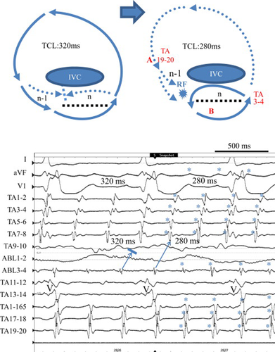
Schema of the tachycardia before and after the lateral cavo-tricuspid isthmus ablation (upper) and acceleration of the tachycardia cycle length (TCL) during radiofrequency (RF) energy delivery (lower) in Case 3. Upper: Schema of dual-loop reentry consisted of a circuit around the tricuspid annulus (TA) and the longitudinal dissociation (dotted line) along the cavo-tricuspid isthmus before (left) and after (right) acceleration of the TCL. Lower: Simultaneous recordings of surface ECG leads I, aVF, and V1, intracardiac recordings around the TA from the coronary sinus ostium (TA 1–2) to the lateral right atrium (TA 19–20), and the ablation catheter located at the lateral cavo-tricuspid isthmus. During atrial flutter, counter-clockwise conduction around the TA appears. Note that the TCL shortened suddenly from 320ms to 280ms (⁎) without termination during RF energy delivery. V=ventricular activation.
Entrainment from the high lateral right atrium (TA 17–18, site A) at a cycle length of 260 ms demonstrated a prolonged PPI of 330 ms compared with the TCL of 280 ms (Fig. 7, upper). The last captured beats (⁎) around the TA were the first beat after the stimulus except the late component of the double potentials (TA 3–4 to TA 5–6) and ablation catheter potentials (ABL1–2 and 3–4) located at the posterior cavo-tricuspid isthmus. On the other hand, entrainment from the anterior cavo-tricuspid isthmus (site B) using an 8-mm-tip ablation catheter at a cycle length of 260 ms demonstrated a PPI of 280 ms, the same as the TCL, and the last captured beats around the TA including double potentials were the first beat after the stimulus (Fig. 7, lower). Radiofrequency energy delivered to the anterior cavo-tricuspid isthmus terminated the atrial tachycardia. These findings suggested that the localized atrial reentry due to longitudinal dissociation along the cavo-tricuspid isthmus became the dominant circuit of dual-loop reentry after lateral isthmus ablation (Fig. 6, upper schema).
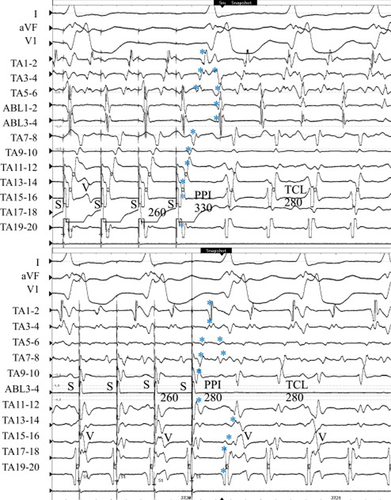
Entrainment from the lateral right atrium and the anterior cavo-tricuspid isthmus in Case 3. Upper: During entrainment from the lateral right atrium at a pacing cycle length of 260ms, the last captured beats (⁎) along the cavo-tricuspid isthmus (late component of double potentials) and ablation catheter potentials located at the posterior cavo-tricuspid isthmus were the second beat after the stimulus. The postpacing interval (PPI) was 330ms, which was prolonged compared with the tachycardia cycle length (TCL). Lower: During entrainment from the anterior cavo-tricuspid isthmus at a pacing cycle length of 260ms, all of the last captured beats (⁎) became the first beat after the stimulus and the PPI was 280ms, the same as the TCL. ABL1–2 potential was omitted because of high amplitude stimulation artifact and PPI was evaluated at the TA11–12 close to the ABL distal electrode. V=ventricular activation.
4 Discussion
Recent advances in three-dimensional electroanatomical mapping systems are useful for locating complex types of atrial reentrant circuits [1], [2]. However, there have been limited data on the functional relation of these reentrant circuits. In the present study, entrainment mapping using the activation sequence of the last captured beats clearly demonstrated the complex dynamic relation of dual-loop reentrant circuits.
In Case 1, dual-loop reentry consisted of the TA and the localized circuit at the CS ostium. The impulse propagated to the left lateral extent of the CS and in the counter-clockwise direction around the TA to the right atrium. Although the impulse simultaneously propagated in both the left and right atrium, the exit sites from the dominant localized reentrant circuit were anatomically different (Fig. 1, upper).
A longer PPI from pacing at the cavo-tricuspid isthmus in a patient with the common type of atrial flutter was reported by Wong [5]. The decremental conduction within the reentrant circuit may contribute to the prolonged PPI; the degree of PPI prolongation from the TCL was 70 ms in their case. In the present case, the difference between the PPI from pacing at the cavo-tricuspid isthmus and the TCL was 140 ms, which was much longer than in reported cases, suggesting that the cavo-tricuspid isthmus was not on the dominant reentrant circuit (Fig. 8A). During entrainment from the cavo-tricuspid isthmus (site A), the long antidromic penetration through the right atrial free wall (n) collided with the orthodromic activation (n−1) through the slow conduction area (crosshatch) within the CS ostium from the septal isthmus. Entrainment from the cavo-tricuspid isthmus suggested the presence of counter-clockwise conduction through the septal isthmus, but the longer conduction time through the slow conduction area could not maintain reentry around TA and instead localized reentry at CS ostium.
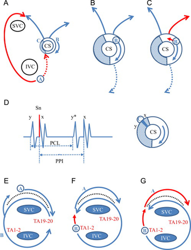
Schema of reentrant circuit in Cases 1 and 2. (A) Entrainment from the cavo-tricuspid isthmus (site A) in Case 1. The long antidromic penetration (n) through the right atrial free wall (red line) collided with the orthodromic wavefront (n−1) from the localized reentry at CS ostium. The localized reentry circuit at the CS ostium was entrained by the activation from the cavo-tricuspid isthmus conducted through the septal isthmus. (B) Entrainment from the CS proximal (site B) at a cycle length of 240ms in Case 1. The slow conduction area (crosshatch) of the localized reentry was located distal to site B. Both the orthodromically captured last beats of the TA and those of the CS were the second beat after the stimulus. (C) Entrainment from the CS proximal (site B) at a cycle length of 220ms in Case 1. The orthodromically captured last beats of the TA were the second beat, but those of the CS became the first beat after the stimulus. It is possible that the antidromic penetration of the localized reentry circuit by the shorter pacing cycle length (red line) revealed the two different exit sites to the CS and the right atrium. (D) Entrainment from the posterior roof of the CS ostium (site C) in Case 1. During entrainment, the preceding small electrogram (y) before stimulation artifact could be recognized. The last stimulus captured both the potential just after the stimulus (x) and the next preceding potential (y). PCL=pacing cycle length, PPI=postpacing interval. (E) Entrainment from the corridor between the trans-septal incision line and the tricuspid annulus (TA) in Case 2. During entrainment from site A, the orthodromically captured clockwise (CW) activation at the corridor was followed by the orthodromic counter-clockwise (CCW) activation around the TA posterior to the incision line. This suggested the activation could turn around the septal edge of the incision line. (F) Entrainment from the low lateral tricuspid annulus (TA) at a cycle length of 250ms in Case 2. During entrainment from site B, the orthodromically captured CCW activation around the TA posterior to the incision line was followed by the orthodromic CW activation at the corridor. (G) Entrainment from the low lateral tricuspid annulus (TA) at a cycle length of 230ms in Case 2. During entrainment from site B at a shorter cycle length, the deeper antidromic penetration of the lateral TA (red line) entered the corridor in association with the orthodromic CW activation (red line). Therefore, the return cycle of the CW activation along the incision line (Fig. 5, #) was less than the TCL.
The PPI from the CS ostium was close to the TCL, suggesting that the CS ostium was on the dominant circuit (Fig. 8B). During entrainment from the CS ostium, the last captured beat of the TA was the second beat after the stimulus, suggesting that the slow conduction area (crosshatch) was located distal to the site B and that the TA was not involved within the dominant circuit (Fig. 8B). At a pacing cycle length of 240 ms, the last captured beat of the CS was the second beat, which changed to the first beat after shortening of the pacing cycle length to 220 ms (Fig. 8C). This change could be explained by the antidromic penetration of the reentrant circuit by the shorter pacing cycle length (Fig. 8C, red line) [3]. The different response between the CS and the right atrium suggested the anatomically different exit sites from the dominant localized reentrant circuit to the right atrium and the CS. During entrainment from the CS ostium, TA1–2 was captured antidromically, suggesting the presence of clockwise conduction through the septal isthmus.
The fractionated potential was observed at the roof of the CS ostium (Fig. 3), and all of the last captured beats became the first beat after the stimulus from the roof of the CS ostium, suggesting that the dominant reentry circuit was localized at the CS ostium. During entrainment, the preceding small electrogram (y) before stimulation artifact could be recognized (Fig. 3, upper). Therefore, the last stimulus captured both the potential just after the stimulus (x) and the next preceding potential (y) (Fig. 8D), likely because there was a gap between x and y potential, and x potential had a lower threshold than y potential. Although y potential was clear, it was difficult to determine the initial point of x potential because both y and x potentials showed continuous fractionated potential. If we define x potential as the latest component of the fractionated potential, PPI became 260 ms, equal to TCL (Fig. 3, red arrow). The cause of fractionated potential in the CS is attributable to anisotropic conduction due to the complex anatomy of the CS muscular cuff [6], [7]. Tonet et al. reported a patient with localized reentrant atrial tachycardia at the CS ostium [8]. Fragmented potential with longer duration of electrograms associated with significant conduction delay were recorded at the CS ostium.
In Case 2, we demonstrated dual-loop reentry consisting of the TA and the superior trans-septal incision. The dual-loop reentry after open heart surgery has been well studied by three-dimensional electroanatomical mapping [1], [9]. However, the dynamic relation of dual-loop reentry around the TA and the superior trans-septal incision was not clear [10]. In case 2, the prolonged PPI at the corridor between the TA and the superior trans-septal line suggested that the circuit around the superior trans-septal incision was not a dominant circuit (Fig. 8E). During entrainment from the TA circuit, shortening the pacing cycle length from 250 ms to 230 ms changed the activation sequence of the last captured beats after the stimulus because of the antidromic penetration (Fig. 8F and G, red line) to the circuit around the TA. Antidromic penetration to the circuit not only changed the excitation wave morphology but also shortened the return cycle compared to the TCL (Fig. 5, #). The deeper antidromic penetration through the TA entered the corridor between the TA and the trans-septal incision line. This activation showed a shortened return cycle despite the fact that the excitation wave forms were nearly the same as those during entrainment, because the captured activation sequence of the corridor was orthodromic (Fig. 8G). The common pathway of this dual-loop reentry between the TA and the trans-septal incision line was located posterior to the trans-septal incision line.
In Case 3, we revealed dual-loop reentry around the TA and the longitudinal dissociation along the cavo-tricuspid isthmus. Lateral cavo-tricuspid isthmus ablation shortened TCL without termination. Before the lateral cavo-tricuspid isthmus ablation, clockwise conduction through the posterior isthmus (n) could not turn around the lateral edge of the longitudinal dissociation of the isthmus and was blocked by the counter-clockwise conduction (n−1) from the lateral TA (Fig. 6 upper left and arrow from ABL3–4 in lower panel). It is possible that the lateral cavo-tricuspid isthmus ablation changed the anisotropic conduction, the clockwise conduction through the posterior isthmus could turn around the lateral isthmus, and counter-clockwise conduction through the anterior isthmus returned to the CS ostium (Fig. 6, upper right). During entrainment from the right atrial free wall (TA17–18, site A), counter-clockwise activation of the right atrial free wall could enter the anterior isthmus and demonstrated a prolonged PPI (Fig. 7, upper). The last captured beats of the late component of the double potentials along the cavo-tricuspid isthmus were the second beat after the stimulus. Both the prolonged PPI and the delayed capture of the double potential suggested that the entrainment site was not on the dominant circuit. On the other hand, entrainment from the anterior cavo-tricuspid isthmus (site B) demonstrated the same PPI as the TCL and all of the last captured beats became the first beat after the stimulus (Fig. 7, lower). Localized atrial tachycardia from the septal isthmus and CS ostium has been reported by Yang et al. [11]. In Fig. 6, no double potentials in TA3–4 and TA5–6 could be observed because of an anterior shift in the TA catheter (a larger ventricular activation wave in TA 11–12 and TA13–14). In Fig. 7, as the TA catheter shifted to the posterior side (larger atrial activation wave in TA 11–12 and TA13–14), double potentials in TA3–4 and TA5–6 reflecting longitudinal dissociation of the isthmus could be recognized.
After overdrive pacing, excitation that is one lap behind (the second beat after the stimulus) is caused by several mechanisms. One is the prolonged conduction time that is longer than the TCL due to a long conduction pathway and/or slow conduction. The other is the dual-loop reentry [12]. The excitation wavefront induced by the overdrive stimulation entered one circuit after going around the other, so the penetration to the other reentry circuit became the second beat after the stimulus. Entrainment mapping using the activation sequence of the last captured beat is very useful for clarifying the complex relation of these reentrant circuits.
The fourth criterion of reentry requires entrainment with shorter pacing cycle lengths in order to detect antidromic penetration into the reentrant circuit [13]. In Cases 1 and 2, entrainment with a shorter pacing cycle length demonstrated antidromic penetration to the circuit and changed the activation sequence of the last captured beats depending on the functional relation of reentrant circuits. However, it is sometimes difficult to determine changes induced by antidromic penetration, because the entrainment at shorter cycle lengths risks termination of the tachycardia and a catheter must be positioned precisely where antidromic penetration changes.
In conclusion, a PPI is obtained from the pacing site only, but the last captured beats could be obtained from all electrodes and it would be advantageous to use the information from all of these available electrode recordings. Analysis of the activation sequence of the last captured beats is useful for revealing the dynamic relation between the complex reentrant circuits.
Conflicts of interest
The authors declare no conflicts of interest.
Acknowledgments
We thank Dr. Eriko Yokoyama for technical assistance and evaluation of the electrophysiological study.


