Volume 100, Issue 9 e202000203
SPECIAL ISSUE PAPER
Open Access

Ludwig Föppl and Gerhard Schubert: Unknown classics of contact mechanics

Elena Popova

Corresponding Author

Elena Popova

Technische Universität Berlin, Berlin, Germany

Correspondence

Elena Popova and Valentin L. Popov, Technische Universität Berlin, 10623 Berlin, Germany

Email: [email protected]  (E.P.); [email protected]  (V.L.P.)

Search for more papers by this author
Valentin L. Popov

Corresponding Author

Valentin L. Popov

Technische Universität Berlin, Berlin, Germany

Correspondence

Elena Popova and Valentin L. Popov, Technische Universität Berlin, 10623 Berlin, Germany

Email: [email protected]  (E.P.); [email protected]  (V.L.P.)

Search for more papers by this author
First published: 07 September 2020
Citations: 10

Abstract

At the beginning of 1941, Professor Ludwig Föppl published an eight-page paper “Elastische Beanspruchung des Erdbodens unter Fundamenten” (Elastic stress in the ground under foundations). It was further developed by his doctoral student Gerhard Schubert and led to a publication by Schubert in 1942, which contains many results obtained by researchers in contact mechanics in the subsequent decades of the 20th century and would make many of these efforts unnecessary… if it had become known. Unfortunately, both papers have been forgotten, which is not particularly surprising considering the years when they appeared (1941–1942), the language (German), as well as the location of the publisher (Munich). Yet, these are true classic works that are still very worth reading, not just as historical artifacts, but also in terms of content. It is most regrettable that this excellent work, which in itself nearly represents a small “handbook of contact mechanics”, remained essentially unknown for a long time and has only been “rediscovered” in recent years. The present paper provides a historical background and a guideline to the mentioned works by Föppl and Schubert, followed by a complete English translation of Schubert's paper.

1 INTRODUCTION

The name Föppl is well known in the German mechanics community. Students studying applied mechanics become acquainted with this name already in their first semester due to the “Föppl brackets”. When speaking about Föppl, we have to specify what Föppl is meant, as both August Föppl (the author of the Föppl brackets) and his sons Ludwig Föppl and Otto Föppl were well-known German engineers. Together with both sons, August Föppl published textbooks on applied mechanics, in particular a fundamental treatise on applied mechanics, “Drang und Zwang. Eine höhere Festigkeitslehre für Ingenieure” (a free translation of this title into English could be “Stress and strain. An advanced strength theory for engineers”) [1, 2]. August Föppl was a member of the Editorial Board of the ZAMMZeitschrift für Angewandte Mathematik und Mechanik—from its foundation in 1921 to his death in 1924. Ludwig Föppl succeeded his father as professor at the Technische Hochschule Munich in 1922 and as a member of the Editorial Board of ZAMM in 1925 [3].

The present paper is devoted to the works of Ludwig Föppl and his doctoral student Schubert on contact mechanics. However, anybody who tries to find something on this topic in Wikipedia or in historical works of contact mechanics and tribology will fail. The Wikipedia article about Ludwig Föppl as of 2020 is devoted mostly to his work as a cryptanalyst during World War I [4]. Indeed, starting as a volunteer in the wireless telegraphy service, he ended up as head of the Signals Evaluation Office of the Sixth Army [5]. However, his main contributions are surely in mechanics, and in particular in contact mechanics.

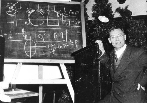
Let us sketch in brief the most important stations of the biography of Ludwig Föppl. He was born on 27. February 1887 in Leipzig as son of August Föppl, later professor at the Technische Hochschule Munich and lived in Munich since 1894. He studied Mechanical Engineering, Physics, and Mathematics in Munich and Göttingen. He carried out his doctoral work in Göttingen under supervision of David Hilbert, and after that, he was an assistant of Felix Klein. He habilitated in Würzburg 1914 aged 27 and started teaching as Privatdozent at the Physics Institute at the University of Würzburg, working with Wilhelm Wien, the author of the Wien's displacement law, for which Wien received the 1911 Nobel Prize. Ludwig Föppl was brother-in-law of Ludwig Prandtl. After the aforementioned military service, he became professor of mechanics at the Technische Hochschule Dresden in 1920 and professor of mechanics at the Technische Hochschule Munich in 1922 (see Figure 1).
Details are in the caption following the image
Professor Ludwig Föppl at the TH Munich (ca. 1939)

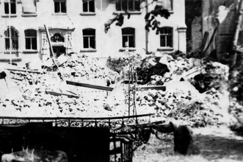
Ludwig Föppl not just worked on mechanics of continua theoretically. He has significantly developed the very important industrial measuring technique of photoelasticity in Germany [6] (Figure 3). During the Second World War, he relocated his residence and photoelasticity laboratory to Ammerland, which may have saved his life, because his house in Munich was hit by an American bomb in an attack on July 12, 1944, and was completely destroyed [8] (Figure 2). 1947–1948, in the particularly difficult period after the Second World War, he directed the reconstruction of the Technische Hochschule Munich (now the Technical University of Munich) as a rector.
Details are in the caption following the image
The rests of the house of Prof. L. Föppl in Munich in Kaiserstraße 11 after an American bomb attack on July 12, 1944
Details are in the caption following the image
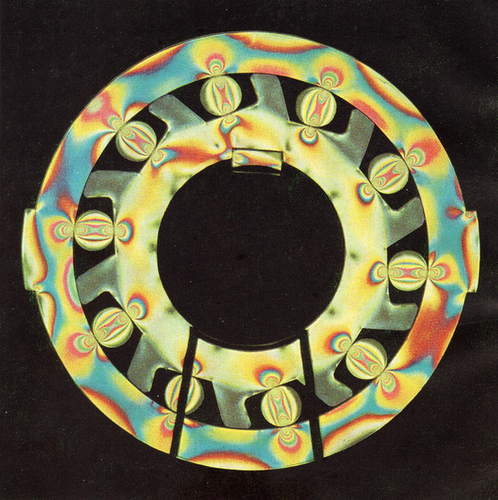
Isochromats in a freewheel model obtained in the photoelasticity laboratory of Ludwig Föppl. A torque acts clockwise on the outer ring. This causes the rollers to jam between the sloped surfaces of the inner ring and the outer ring. Model made of unsaturated polyester resin VP 1527, 10 mm thick, diameter 230 mm. Reproduced from [7]
Photoelasticity studies gave Föppl the possibility to “see” the stress state, as he writes in the preface to [6] (Figure 3). Further, it was his photoelasticity laboratory, which gave him the possibility to continue working in the first years of the Second World War. In his private, not published memoirs [8], he writes about the time around 1940th:

“…Above all, photoelasticity was promoted. Since our institute was a leader in this field in Germany, we received orders from the industry. Among them were those that were considered important for the war and therefore had to be treated preferentially. This gave me the opportunity to apply for my assistants and close co-workers to be classified as ‘indispensable’ and as such I was able to protect them from being drafted. The stock of urgently important tasks, especially in the field of photoelasticity issues, increased, so that I was able to request previous employees who were in the field. In this way, I managed to pull some valuable young people from the front and thereby save them from the worst…” [8].

Note that L. Föppl had rescued talented young people during the First World War too. M. Samuels writes about Föppl's time in the army [5]:

“…Föppl found that he was able to use the importance of the decryption work as a means to rescue bright young men from the fighting…”

The treatise of engineering mechanics mentioned at the beginning already contained the classic parts of two- and three-dimensional contact mechanics. However, it was the eight-page paper “Elastic stress in the ground under foundations” of 1941 [9], which was a breakthrough in contact mechanics of arbitrarily shaped axisymmetric bodies. In this paper, Föppl determined the deformation of the surface of an elastic half-space under the action of arbitrary plane as well as arbitrary axis-symmetric pressure distribution, in a form that allowed a simple inversion and thus solution of an arbitrary contact problem. This inversion was made in the dissertation of his doctoral student Gerhard Schubert, whose dissertation was published in a shortened form in 1942 [10]. In spite of the fundamental and comprehensive results of this paper, it remained widely unknown. The reasons for this are obvious: The paper was published in Munich, in German language during the Second World War. Deep gaps separated German scientists from the rest of the world not only during the war but also in the first post-war years, so the work fell into oblivion. To remind of the realities of the time, it is instructive to read what Föppl writes in the preface to his postwar publication on rolling friction (dated with January 1947) [11]:

The present work originated in the last period of the war. Since the work will presumably also be read abroad, it might not be without interest for the foreign colleagues to learn under what conditions the German scientists carried out their research during the period of terror. The many German scholars who, like the author, hated the Nazi tyranny from the outset, could only survive in Germany by withdrawing as much as possible from public affairs and concentrating on their science. A lot of valuable scientific work has been done in Germany since 1933. As far as it was created during the war, it has largely not yet been published. This work is also the first in a series of unpublished works by the author that has been printed. Hardly any foreign colleague, who has not felt the tyranny of the system firsthand, can imagine under what kind of mental pressure through the Nazis this work was created. May our colleagues abroad take into account in their thoughts about German scientists that very many of us have suffered more from this pressure than is generally assumed abroad. With the spread of this insight, I hope that the deep gap that separates German science from foreign science will be gradually bridged. The scientists who serve the truth and who apply the same laws to their research regardless of political borders and apply the same standards to the results of this research are primarily called to shake hands across borders. May this work help it!…

As a matter of fact, Ludwig Föppl was doubly hindered from being taken up more widely, as he suffered from being German (and hence rejected by much of the wider academic world) and also part of the passive resistance to the Nazis (and hence unlikely to have his work promoted officially prior to the end of the war).

The paper by Föppl from 1941 was only a small episode in his mechanics research work. For Schubert, this was his only work on contact mechanics. After his doctoral examination on January 12, 1941, Schubert worked in the physics department, in particular on low temperature physics, first at the Technische Hochschule Munich. 1950 he became a professor for theoretical physics at the University of Mainz, where he served also as Director of the Institute of Theoretical Physics and Dean of the Faculty of Physics (Figure 4) [12].

Details are in the caption following the image
Gerhard Schubert 1977 as dean of the Physics Faculty of the University of Mainz. (Photo by Reiner Wierick)

2 SOLUTIONS OF AXISYMMETRIC CONTACT PROBLEMS ACCORDING TO FÖPPL AND SCHUBERT

In this section, we will briefly sketch the derivation of the solution for the contact problem of an arbitrary axially symmetric indenter, which was published 1941 by Föppl [9] and 1942 by Schubert [10]. These are the first known publications providing a complete solution to the contact problem for arbitrary axisymmetric bodies with compact contact area. Over the course of the history of contact mechanics, this solution was obtained multiple times using different approaches. For instance, they were later found by Galin in 1946 as well, likely independently [13]. They reached a great degree of international recognition through the paper of Sneddon [14]—one of the most cited publications in the history of contact mechanics. Yet Sneddon merely offers a different derivation approach to obtain already known solutions, including those of Galin (whom he cites). Even much later, new interpretations and derivations of the same equations were published repeatedly. Some of these were quite useful since they provided a new perspective on the issues and facilitated different generalizations and developments. This includes the interpretation by Jäger [15], who treated the indentation of a curved body as the superposition of infinitesimal indentations of flat cylindrical punches (although even this idea was not original and was previously used by Mossakovskii [16]). The solution of Föppl and Schubert was finally transformed into a simple mnemonic rule in the Method of Dimensionality Reduction (MDR) [17-21]. While the MDR is based on the equations of Föppl–Schubert–Galin–Sneddon–Jäger, it also offers an intuitive physical-mnemonic interpretation, which can be directly generalized to many other contact problems. In the meantime, the MDR has been extended to describe tangential contacts, adhesive contacts, viscoelastic contacts, thermal effects in contacts, contacts of functionally graded materials as well as applications to arbitrarily shaped bodies [22, 23].

Although 79 years have passed since the publications of Föppl and Schubert, this first historic derivation remains, surprisingly, still the most direct and simple of all. Both for historic and didactic reasons, it is valuable to understand this derivation. The following presentation of the derivation by Föppl and Schubert very closely follows the original publications; however, modified notations are used to highlight the direct connection to the equations of the MDR. This presentation follows [24].
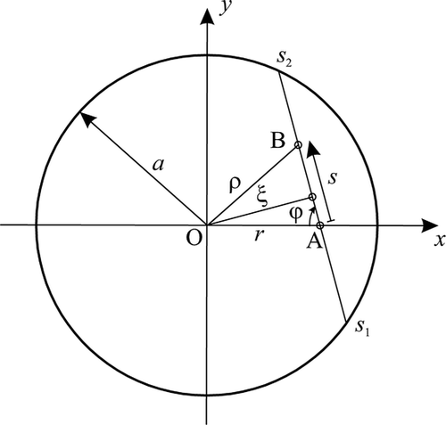
We consider an axially symmetric pressure distribution p ( r ) in a circle of radius a (see Figure 5). We calculate the displacement at the “point of observation” A caused by an infinitesimally small force in the “source point” B and then integrate over all source points. The location of the source point is parametrized by the linear coordinate s and the angle φ. The vertical displacement of the point A by the force d F N = p ( ρ ) s d s d φ in point B is given by the fundamental solution [25, 26]:
d w ( r ) = p ( ρ ) s d s d φ π E s = 1 π E p ( ρ ) d s d φ . (1)
Details are in the caption following the image
Schematic diagram to display the notation proposed by Föppl
The total vertical displacement caused by the entire pressure distribution results from integration
w ( r ) = 1 π 0 π 1 E s 1 s 2 p ( ρ ) d s d φ . (2)
In his paper [9], Föppl proposed to replace the parametrization s and φ with new variables ρ and ξ, which uniquely define the location of the point B, too, and relate to s and φ according to the following equations:
s = ρ 2 ξ 2 + r 2 ξ 2 , ξ ρ a , φ = arcsin ξ r , 0 ξ r . (3)
Accordingly, the derivatives are
s ρ = ρ ρ 2 ξ 2 , φ ξ = 1 r 2 ξ 2 . (4)
Denoting the parenthesized expression in (2) by w 1 D ( ξ ) , we can represent it as:
w 1 D ( ξ ) = 1 E s 1 s 2 p ( ρ ) d s = 2 E ξ a p ( ρ ) ρ d ρ ρ 2 ξ 2 . (5)
For the vertical displacement (2), we then obtain
w ( r ) = 2 π 0 π / 2 w 1 D ( ξ ) d φ = 2 π 0 r w 1 D ( ξ ) d ξ r 2 ξ 2 . (6)

Equation (6) is identical to the Equation (27) of the MDR (see Section 3). Equations (5) and (6) enable the calculation of the displacement field resulting from a known pressure distribution. In his paper, Föppl examined the pressure distributions ( 1 r 2 / a 2 ) 1 / 2 , ( 1 r 2 / a 2 ) 1 / 2 and a constant pressure distribution, demonstrating that the former corresponds to a constant displacement and the second corresponds to a parabolic indenter.

Note that Equation (2) was already used in the book [2] by A. Föppl and L. Föppl in 1920. The new step made by Ludwig Föppl in his paper in 1941 was the transition to the variables ρ and ξ according to (3) and Figure 5. In these (and only these) variables, the contact problem is reduced to a two-step procedure described by Equations (5) and (6) both having the form of Abel-transforms and thus enabling easy handling with known methods. Written in this particular form they enabled easy inversion and thus complete solution of a large class of contact problems. The choice of integration variables ρ and ξ is one of many historical examples when a particular choice of parametrization made history. As it often happened in the history of science, a reduction of the problem statement to a known problem provided its complete solution “at once” [27].

The contribution of the doctoral student of Ludwig Föppl, Gerhard Schubert (1942) was the inversion of the integral Equations (5) and (6). Since these are Abel transforms, Schubert found the solutions
w 1 D ( ξ ) = ξ 0 ξ w ( ρ ) ξ 2 ρ 2 d ρ (7)
and
p ( ρ ) = E π ρ a w 1 D ( ξ ) ξ 2 ρ 2 d ξ , (8)
which are identical to the Equations (28) and (22) of the MDR (see Section 3 as well as Equations (28) and (32) in the English translation of the Schubert's original paper at the end of this historical overview). These two equations are a straightforward consequence of the Föppl's paper and the kernel of the Schubert's paper. The rest of his paper consists of applications of these relations to a great variety of special contact shapes.

The Equations (7) and (8) completely solve the contact problem: with given three-dimensional form w ( ρ ) , using (7), one can calculate the auxiliary function w 1 D ( ξ ) , which then determines the pressure distribution by (8). Schubert used this approach to solve the contact problems of the flat punch, the cone, power law profiles of second, fourth and sixth order, concave power law profiles of second and fourth order, and the cylindrical indenter with rounded edges.

Of course, the publications of Föppl and Schubert did not contain the MDR interpretations of their equations, which requires a couple of additional steps. In the interpretation of the MDR [21], w 1 D ( ξ ) is the vertical displacement in the equivalent MDR model. The necessary property for the transition to the MDR interpretation is w 1 D ( ξ = 0 ) = w ( r = 0 ) . This equation guarantees that the indentation depth of the three-dimensional profile is also the indentation depth of the equivalent MDR profile. The mentioned property follows from Equation (6), when the limit w 1 D ( ξ = 0 ) is substituted for w 1 D ( ξ ) in the limit case r 0 , while taking into account the identity
2 π 0 r d ξ r 2 ξ 2 1 . (9)
Then
w ( r = 0 ) = lim r 0 w ( r ) = w 1 D ( ξ = 0 ) · 2 π 0 r d ξ r 2 ξ 2 = w 1 D ( ξ = 0 ) . (10)
It follows trivially from (5) that the contact radius is determined by the equation w 1 D ( a ) = 0 . The equation determining the force, (19), follows from (8):
F N = 2 π 0 a p ( r ) r d r = 2 E 0 a ρ a w 1 D ( ξ ) ξ 2 r 2 d ξ r d r = 2 E 0 a w 1 D ( ξ ) 0 ξ r d r ξ 2 r 2 d ξ = 2 E 0 a ξ w 1 D ( ξ ) d ξ = 2 E 0 a w 1 D ( ξ ) d ξ . (11)

It can be easily seen that this equation is equivalent to the Equation (19) of the MDR (see next Section). It is precisely this equation that makes it possible to reinterpret the problem in terms of a fictitious contact with a linear elastic foundation—the main intermediate step of the MDR. Thus, all fundamental equations of the MDR are determined and the only task remaining is to “put them into words”.

Note that the publications by Föppl and Schubert also contain solutions of the plane contact problem. Schubert applies this solution to the following profiles: flat punch with symmetric load, flat punch with axisymmetric load, wedge profiles, parabolically rounded wedge profile, power law profiles of second, fourth and sixth order, concave power law profiles of second and fourth order, and the flat punch with rounded edges.

3 DERIVATIONS OF THE MAIN EQUATIONS OF THE METHOD OF DIMENSIONALITY REDUCTION FOR NORMAL CONTACT OF AXISYMMETRIC PROFILES WITH A COMPACT CONTACT AREA

In this section, we provide an alternative derivation of equations found by Föppl and Schubert. This derivation is based on the idea of Mossakovskii [16] and Jäger [15] to represent the solution to a contact problem of an arbitrary axisymmetric body as a superposition of infinitesimal indentation with flat-ended circular cylinders. According to this idea, the known solution for a rigid cylindrical indenter completely solves the contact problem also for an arbitrary shaped axisymmetric indenter. Accordingly, the knowledge of the solution for indenting a rigid cylinder of an arbitrary radius a is a prerequisite for the derivation. For a contact of a rigid cylinder with an elastic half-space, the solution is known already since Boussinesq [25] (see also [26]). The pressure distribution under a rigid flat-ended cylinder pressed into an elastic continuum by the indentation depth d is equal to
p ( r ) = 1 π E d a 2 r 2 , (12)
where E = E / ( 1 ν 2 ) with E being Young modulus and ν Poisson ratio of the medium. The contact stiffness does not depend on the indentation and is equal to
k z = 2 a E . (13)
The normal displacement of the surface of the elastic body outside the contact is
w r ; a = 2 π d · arcsin a / r , r a . (14)
We now consider the contact between a rigid indenter of the shape z = f ( r ) and an elastic half-space characterized by the effective elasticity modulus E . Let the indentation depth under the effect of the normal force F N be d and the contact radius a. For a given profile shape, any of these three quantities uniquely determines the other two, in particular, the indentation depth is a function of the contact radius, which is denoted by
d = g ( a ) . (15)
Let us examine the indentation process from the first touch to the final indentation depth d, denoting the values of the force, the indentation depth and the contact radius during the indentation by F N , d and a , respectively. The process can then be viewed as a change in the indentation depth from d = 0 to d = d , with the contact radius changing from a = 0 to a = a and the contact force from F N = 0 to F N = F N . The normal force at the end of the process can be written in the following form:
F N = 0 F N d F N = 0 a d F N d d d d d a d a . (16)
Taking into account that the differential stiffness of a zone of radius a is given by
d F N d d = 2 E a (17)
(see Equation (13)) and using the notation (15), we obtain
F N = 2 E 0 a a d g ( a ) d a d a . (18)
Integration by parts now results in
F N = 2 E a · g ( a ) 0 a g ( a ) d a = 2 E 0 a g ( a ) g ( a ) d a = 2 E 0 a d g ( a ) d a . (19)

This equation provides the basis for an intuitive interpretation of the MDR. According to this equation, the normal force can be considered as resulting from the indentation of the profile z = g ( a ) into a one-dimensional elastic foundation with linear stiffness density 2 E .

We now turn our attention to calculating the pressure distribution in the contact area. An infinitesimal indentation of an area of radius a generates the following contribution to the pressure distribution (see Equation (12)):
d p ( r ) = 1 π E a 2 r 2 d d , for r < a . (20)
The pressure distribution at the end of the indentation process equals the sum of the incremental pressure distributions:
p ( r ) = d r d 1 π E a 2 r 2 d d = r a 1 π E a 2 r 2 d d d a d a (21)
or under consideration of the notation (15)
p ( r ) = E π r a 1 a 2 r 2 d g ( a ) d a d a . (22)

The function g ( a ) from Equation (15), therefore, uniquely defines both the normal force (Equation (19)) and the pressure distribution (Equation (22)). The normal contact problem is reduced to the determination of the function g ( a ) , (15).

The function d = g ( a ) can be determined as follows. The infinitesimal surface displacement at the point r = a for infinitesimal indentation by d d of a contact area of radius a < a is according to (14) equal to
d w ( a ) = 2 π arcsin a a d d . (23)
The total vertical displacement at the end of the indentation process is, therefore, equal to
w ( a ) = 2 π 0 d arcsin a a d d = 2 π 0 a arcsin a a d d d a d a (24)
or with the notation (15)
w ( a ) = 2 π 0 a arcsin a a d g ( a ) d a d a . (25)
This vertical displacement, however, is obviously equal to w ( a ) = d f ( a ) :
d f ( a ) = 2 π 0 a arcsin a a d g ( a ) d a d a . (26)
Integration by parts and consideration of the Equation (15) lead to the equation
f ( a ) = 2 π 0 a g ( a ) a 2 a 2 d a . (27)
This is Abel's integral equation, which is solved with respect to g ( a ) in the following way [28]:
g ( a ) = a 0 a f ( a ) a 2 a 2 d a . (28)

With the determination of the function g ( a ) , the contact problem is completely solved.

Equations (19), (22), and (28) are the main equations of the MDR.

Note that the difference between the approach by Föppl and Schubert and that of Jäger (described in this Section) is that Föppl and Schubert proceed from the fundamental solution for a concentrated force, while Jäger starts from the solution for a flat-ended punch. The approach by Jäger is simpler and more intuitive while the approach by Föppl is more straightforward and has no prerequisites.

4 CONCLUSION

The history of science sometimes reads like a detective novel. Like all types of human activity, it is an interweaving of individual destinies and global shocks like wars. The personal destinies sometimes lead to the fact that outstanding, ingenious works which were decades ahead of their time, sink into oblivion. Sometimes it is only the name of the scientist which remains unknown, while his work becomes known due to publication under another name, as in the history of elastohydrodynamics [29]. But sometimes the coincidence of unfavorable circumstances leads to an almost complete oblivion of the work. This seems to have happened with the publications of Föppl and Schubert. A quick screening of the literature of contact mechanics shows that the results obtained by Schubert using the method previously developed by Föppl cover a large amount of results found by dozens of researches during almost half a century. If these two publications became known, contact mechanics would have received a very intensive impetus already 1941. But the history does not know the subjunctive mood…

One cannot say that the papers by Föppl and Schubert have been completely forgotten. In almost 70 years Schubert's paper was cited 52 times (according to Google Scholar as of July 31, 2020). Half of these citations stem from the research group of one of the authors of the present paper. This citation number should be compared with 4327 citations of the paper by Sneddon [14]. From a historical perspective, the paper by Conway from 1956 is worth mentioning [30]. This paper is devoted to contact mechanics of transversely isotropic bodies. The paper is very short (five pages) and consists of three parts: (i) a very good historical overview, where the paper by Schubert is placed in the center; (ii) a reminder of the result by Michell from [31] that the fundamental solution for a transversely isotropic medium is identical to that of an isotropic medium (thus the whole contact mechanics is also identical); and (iii) the brief remark that the calculation method for any isotropic axially symmetric normal contact problem by Schubert [10] can also be applied to the corresponding contact problem of transversely isotropic media. Regrettably, the paper by Conway also went almost unnoticed (it was cited eight times in 64 years).

The equations obtained by Föppl and Schubert became widely known due to publication by Sneddon in 1965, 24 years after the Föppls publication and it took further decades until it became well-known and “established”. However, Sneddon cites Galin but not Schubert.

Neither at the time of the publications by Föppl and Schubert nor at the time of the much later publication by Sneddon, was it noticed that the equations of Föppl–Schubert–Galin–Sneddon allow a simple physical interpretation in terms of an effective contact with a linear elastic foundation. This further step was made in the framework of the MDR. The MDR, according to Barber [32], is basically a reinterpretation of the equations of Föppl–Schubert–Galin–Sneddon using a simple contact with a one-dimensional elastic foundation. MDR summarizes the known solutions and presents them in a simply reproducible mnemonic form. Due to theorems allowing for (exact or approximate) reduction of tangential contact problems (Cattaneo [33]; Mindlin [34]; Jäger [15]; Ciavarella [35]), viscoelastic contact problems (Radok [36]) and adhesive contact problems (Johnson et al. [37]) to non-adhesive normal contact, the MDR becomes a very compact, universal and intuitive tool for understanding and analyzing a great variety of contact problems. In fact, it provides a sort of “pocket edition” of all solutions in contact mechanics of point contacts obtained by researchers in the last 138 years. All major problems of contact mechanics—such as normal and tangential contact, stresses at the surface and inside the material, viscoelastic contacts, adhesion, wear and fretting, influence of shape, and material gradients on adhesive strength and wear as well as damping in oscillating contacts—this complete spectrum of essential contact problems can be analyzed with the MDR without using complicated mathematical tools.

Even if not widely known, Föppl and Schubert initiated this process of drastic simplification of contact mechanics, which finally, due to recent developments, became accessible even to students of physics or engineering in the first semester. The parametrization invented by Föppl remains to our day the most simple and elegant method of solving contacts with axisymmetric contact problem. It can be strongly recommended to anyone who teaches contact mechanics.

As an attachment to this paper, the reader will find a complete English translation of the paper by Schubert “On Stress Distribution under Elastically Mounted Load Bearing Structures. We refrained from translating the paper by Föppl from 1941, which provides the starting point for the Schubert's paper, because the transformation proposed by Föppl is explained and cited in Schubert's paper.

ACKNOWLEDGMENTS

The authors thank the grandson of Ludwig Föppl, Martin Samuels, and granddaughter of Ludwig Föppl, Sabine Föppl, for providing documents and photographs from the family archive and inspiring discussions. We further thank the head of the archive of the University of Mainz, Dr. Christian George, for providing biographical information and a photo of Gerhard Schubert taken by Reiner Wierick. We thank Iakov Lyashenko and Nikita Popov for their assistance in preparing and proofreading the manuscript. The following translation of Schubert's paper was performed by Joshua A. Gray and Valentin L. Popov.

Open access funding enabled and organized by Projekt DEAL.

    image

    On stress distribution under elastically mounted load bearing structures

    By Gerhard Schubert in Munich

    1. Assumptions. Here, we will follow up the work of L. Föppl, “Elastic Loading of the Ground beneath Bedplates”. We assume that the ground is composed of a homogenous, isotropic material that follows Hooke's law. Thus, we neglect any possible plastic deformations. Furthermore, we assume the force of friction between the structure and ground is negligible and set it equal to zero from the beginning. This is not only possible when using the ground as a substrate, but also for other materials [see Okubo]. From the multitude of possible forms of substrates, we choose two. First, we investigate the infinitely extended half-plane, in which a two-dimensional state of stress appears due to the pressure from a structure. Then, we investigate an axisymmetric case. If one wishes to consider instead a two-dimensional deformation state, then one must only replace E with E = E m 2 m 2 1 in the equations derived in the following.

    To begin with, we envision the structure to be infinitely rigid with respect to the substrate and specify the form of the pressure surface. This means that we prescribe a perpendicular displacement of the substrate boundary within a particular domain. The pressure to be determined is distributed over the domain in such a way as to result in the given displacement. Outside of the considered domain, it is only required that the surface forces vanish at the boundary of the substrate. Once the pressure distribution is determined, it is irrelevant whether one considers the displacement of the substrate surface to be caused by a rigid bedplate or if the lower bedplate surface is an “elastic surface”. In this way, our considerations are also important for the theory of flexible load bearing structures on elastic substrates.
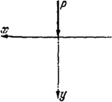
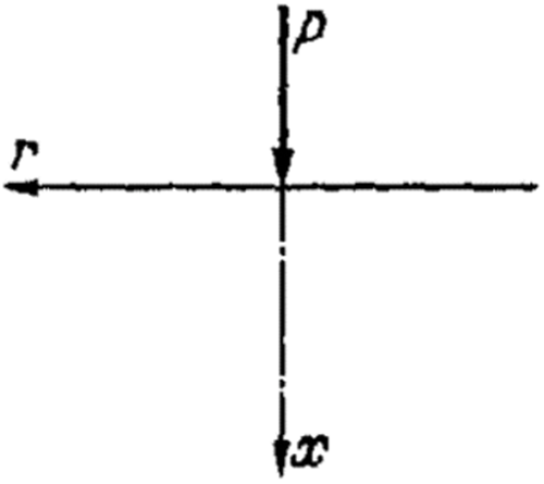
    2. Formulation of the integral equations. (a) Two-dimensional state of stress. We set up the calculation using a right-handed Cartesian coordinate system ( x , y ) . Let the elastic displacement along the y - axis be η. The equation for the interface between the bedplate and the substrate is y = 0 . We assume, according to Figure 1, a single load P normal to the interface. Thereby, P has the units force per unit length. The theory of elasticity provides for the derivative of η with respect to x.
    η x y = 0 η x , 0 ( x ) = 2 P π E 1 x . (1)
    Details are in the caption following the image
    Point load on a half-plane
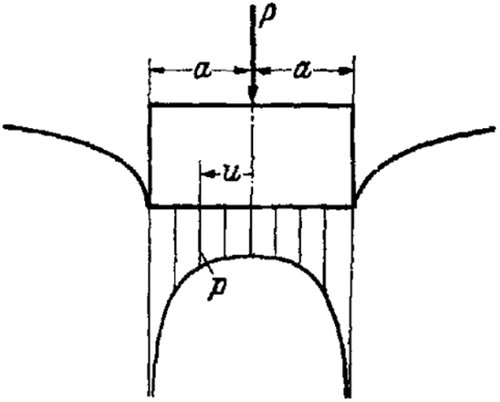
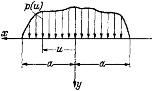
    For a continuous load distribution, integration according to Figure 2 provides
    η x , 0 ( x ) = 2 π E a + a p ( u ) x u d u , (2)
    or with
    f ( x ) E 4 η x , 0 ( x ) (3)
    and, ultimately, for | x | a ,
    f ( x ) = 1 2 π a + a p ( u ) u x d u . (4)
    Details are in the caption following the image
    Continuous pressure distribution
    Details are in the caption following the image
    Point load on a half space

    Equation (4) is to be solved with respect to p ( u ) .

    (b) Rotationally-symmetric state of stress. We transfer everything to a cylindrical coordinate system ( r , α , x ) , where all quantities are independent from the azimuth α. According to Boussinesq, the displacement ξ in the x- direction at the edge for a point load on an infinite half-space is
    ξ x = 0 ξ 0 = P π m 2 1 E m 2 1 r = P π E 1 r . (5)
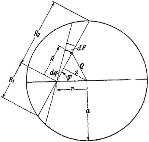
    In order to find ξ0 for a rotationally-symmetric load p ( r ) over a circle with a radius of a, one proceeds according to L. Föppl, using the nomenclature defined in Figure 4, in the following way. Imagine a force p ( R , φ ) R d φ d R at the origin ( R , φ ) that corresponds, according the Equation (5), to the displacement
    d ξ 0 = 1 π E p ( R , φ ) d φ d R
    at the point r. Integration with respect to R results in
    d ξ 0 = 1 π E d φ R 1 R 2 p ( R , φ ) d R .
    Details are in the caption following the image
    Continuous rotationally-symmetric loading
    We set
    R 1 R 2 p ( R , φ ) d R = Φ 1 ( φ ) , (6)
    resulting in
    ξ 0 = 2 π E 0 2 / π Φ 1 ( φ ) d φ .
    Inserting z = r sin φ , we obtain
    ξ 0 ( r ) = 2 π E 0 r Φ ( z ) r 2 z 2 d z with Φ ( z ) Φ 1 arcsin z r . (7)
    In order to calculate Φ according to Equation (6), it proves useful to introduce a variable ϱ such that
    R = r 2 z 2 + ϱ 2 z 2 , d R d ϱ = ϱ ϱ 2 z 2 .
    Due to the fact that p is only dependent on ϱ, Equation (6) becomes especially simple:
    Φ ( z ) = 2 z a p ( ϱ ) ϱ ϱ 2 z 2 d ϱ . (8)

    Thus, we have the integral equations Equation (7) and Equation (8) to determine p ( ϱ ) .

    3. Solution of the integral equations. (a) Inverse transformation for Equation (4). First, let it be mentioned that kernel of Equation (4) is so singular that one must use the Cauchy principle value. Hamel states the solution to Equation (4) in the form of a series expansion. With
    x = a cos φ , u = a cos ψ , (9)
    Equation (4) becomes
    f ( a cos φ ) = 1 2 π 0 π p ( a cos ψ ) sin ψ cos φ cos ψ d ψ . (10)
    Let us express the function f ( a cos φ ) sin φ as a Fourier series, namely, as an odd function of φ in a series with sin terms:
    f ( a cos φ ) sin φ = 1 2 n = 1 b n sin n φ (11)
    with
    b n = 4 π 0 π f ( a cos φ ) sin φ sin n φ d φ . (12)
    Equation (10) becomes
    1 π 0 π p ( a cos ψ ) sin ψ cos φ cos ψ d ψ = n = 1 b n sin n φ sin φ . (13)
    However, the following integral formula is valid:
    1 π 0 π cos n ψ cos φ cos ψ d ψ = sin n φ sin φ ( n = 0 , 1 , 2 , 3 , ) . (14)
    A comparison of Equation (13) and Equation (14) leads to
    p ( a cos ψ ) = 1 sin ψ b 0 + n = 1 b n cos n ψ . (15)
    This is Hamel's solution, in which b0 is initially an arbitrary constant. We determine it using the mechanical equilibrium condition
    P = a a p ( u ) d u = a 0 π p ( a cos ψ ) sin ψ d ψ . (16)
    In this case, P is the total load. From Equation (15) and Equation (16), we obtain
    b 0 = P π a . (17)
    Now, we want to rearrange Hamel's solution with the intention of obtaining an integral presentation of the solution. To this end, we substitute Equation (12) into Equation (15) and write the infinite series as the limit of the sum of N terms:
    p ( a cos ψ ) = 1 sin ψ P π a 4 π lim N n = 1 N 0 π cos n ψ f ( a cos φ ) sin φ sin n φ d φ . (18)
    For a finite number of terms, we may interchange between the serial and integral forms:
    p ( a cos ψ ) = 1 sin ψ P π a 2 π lim N 0 π f ( a cos φ ) sin φ n = 1 N 2 cos n ψ sin n φ d φ . (19)
    With the help of the familiar formula
    n = 1 N sin n α = sin N + 1 2 α sin N 2 α sin α 2 = cos α 2 cos 2 N + 1 2 α 2 sin α 2 , (20)
    we obtain the following after a few intermediate steps:
    n = 1 N 2 cos n ψ sin n φ = n = 1 N sin n ( φ + ψ ) + sin n ( φ ψ ) = sin φ + sin N φ cos ( N + 1 ) ψ sin ( N + 1 ) φ cos N ψ cos ψ cos φ . (21)
    We insert Equation (21) into Equation (19) and obtain
    p ( a cos ψ ) = 1 sin ψ P π a 2 π 0 π f ( a cos φ ) sin 2 φ cos ψ cos φ d φ + 1 2 lim N L N (22)
    with
    L N 4 π cos N ψ 0 π f ( a cos φ ) sin φ sin ( N + 1 ) φ cos ψ cos φ d φ cos ( N + 1 ) ψ 0 π f ( a cos φ ) sin φ sin N φ cos ψ cos φ d φ . (23)
    In order to calculate L N , we substitute the general term 1 2 b k sin k φ of the series in Equation (11) into Equation (23). Then, with L N = k = 1 L N k , the general term becomes
    L N k = b k 2 2 cos N ψ 1 π 0 π cos ( N + 1 k ) φ cos ( N + 1 + k ) φ cos ψ cos φ d φ 2 cos ( N + 1 ) ψ 1 π 0 π cos ( N k ) φ cos ( N + k ) φ cos ψ cos φ d φ .
    From this, the integral formula Equation (14) provides
    L N k = b k 2 sin ψ 2 cos N ψ sin ( N + 1 k ) ψ sin ( N + 1 + k ) ψ 2 cos ( N + 1 ) ψ sin ( N k ) ψ sin ( N + k ) ψ = 0 ,
    at the end of the calculation, and consequently,
    L N = 0 , lim N L N = 0 . (24)
    If we once again substitute the variables x = a cos φ and u = a cos ψ into Equation (22), it becomes
    p ( u ) = 1 π a 2 u 2 P + 2 a a f ( x ) a 2 x 2 u x d x (25)
    or, according to Equation (3),
    p ( u ) = 1 π a 2 u 2 P + E 2 a a η x , 0 ( x ) a 2 x 2 u x d x . (26)
    If the displacement η is symmetric with respect to the y - axis (i.e., η x , 0 ( x ) = η x , 0 ( x ) ), then one may easily rearrange Equation (26) to
    p ( u ) = 1 π a 2 u 2 P + E 0 a η x , 0 ( x ) x a 2 x 2 u 2 x 2 d x . (27)

    Let us point out that there are two conditions that p ( u ) must satisfy. First, we assume pressure p to be positive. When the structure is slightly lifted, no tension forces are able to be transferred from the structure to the bedplate. Therefore, p ( u ) may not be negative for | u | a . For cases meeting this requirement, the contact length 2a may be determined. Second, the static equilibrium conditions must be satisfied for the body of the structure. The infinite substrate should be thought of in such a way that it is in equilibrium. The equilibrium of the substrate with respect to parallel displacement requires that the parallel component of load vanishes, due to the lack of frictional forces. The equilibrium with respect to the displacement in the y - direction is assured due to Equation (17). In the most general case resultant force from p ( u ) and the load will not have the same line of action when p ( u ) is calculated according to Equation (26). In order to also establish equilibrium of moments, it is necessary to take the rotation of the bedplate into account by including an additional arbitrary constant in the expression of η x , 0 ( x ) . This is then included in p ( u ) and can be determined from the moment equation.
    (b) Inverse transformations for Equation (7) and Equation (8). According to Abel, the solution of Equation. (7) is
    Φ ( z ) = E ξ 0 ( 0 ) + z 0 z ξ 0 ( r ) z 2 r 2 d r . (28)
    Here, ξ0(0) is a constant that plays no role, as we will see. In order to now solve Equation (8) with respect to p ( ϱ ) , we start with the identity
    Φ ( z ) = Φ ( a ) 2 π z a Φ ( s ) π 2 d s . (29)
    Furthermore, it can be easily shown that the following equation is valid:
    z t ϱ ( t 2 ϱ 2 ) ( ϱ 2 z 2 ) d ϱ = π 2 . (30)
    Therefore, we can write Equation (29) in the following form when we choose t = a for the first term and t = s for the second:
    Φ ( z ) = 2 π z a Φ ( a ) ϱ ( a 2 ϱ 2 ) ( ϱ 2 z 2 ) d ϱ z a ds z s Φ ( s ) ϱ ( s 2 ϱ 2 ) ( ϱ 2 z 2 ) d ϱ .
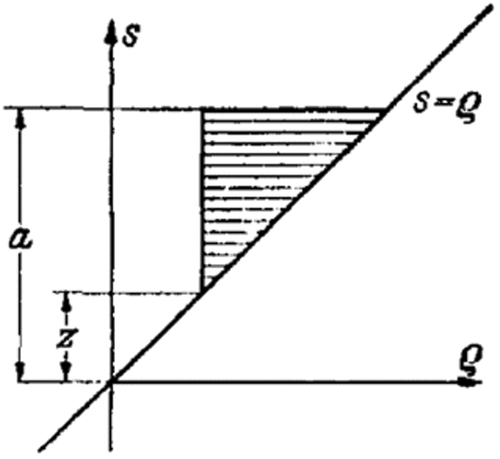
    The double integral should be taken over the hatched domain in Figure 5. By changing the order of the integrals, one obtains
    Φ ( z ) = 2 z a ϱ ϱ 2 z 2 1 π Φ ( a ) a 2 ϱ 2 ϱ a Φ ( s ) s 2 ϱ 2 ds d ϱ . (31)
    Details are in the caption following the image
    (ϱ, s) - plane
    Details are in the caption following the image
    Example (a)
    Comparing Equation (31) with Equation (8) provides the following inverse transformation for the equation:
    p ( ϱ ) = 1 π Φ ( a ) a 2 ϱ 2 ϱ a Φ ( s ) s 2 ϱ 2 ds . (32)
    The static equilibrium conditions are limited, due to reasons of symmetry, to
    2 π 0 a p ( ϱ ) ϱ d ϱ = P . (33)

    This final equation (Equation 32) only contains the integration constant ξ0(0) within the expression Φ ( a ) , which we can insert as a new integration constant. If a is known from the beginning and p ( ϱ ) is not negative for ϱ a , then we determine Φ ( a ) with the help of Equation (33). However, if p ( ϱ ) is negative for 0 < c ϱ a , then we must consider a as a parameter in Equation (32) to be calculated from p ( a ) = 0 , which is, according to the definition in Equation (6), synonymous with Φ ( a ) = 0 . Thereby, the constant is already established and we must find a in such a way that the necessary condition Equation (33) is satisfied.

    4. Examples for the two-dimensional problem. (a) The symmetrically loaded substrate by a flat-bottomed bedplate. Let η x , 0 = 0 . With this, Equation (26) provides the familiar result
    p ( u ) = P π a 2 u 2 = 2 p 0 π 1 u / a 2 , (34)
    in which p 0 = P / 2 a is an equivalent pressure resulting in a uniform pressure distribution.
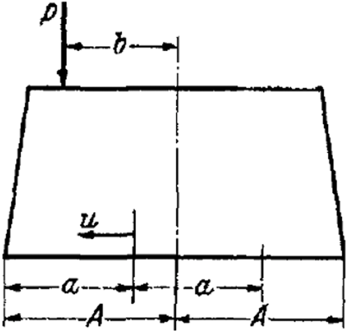
    (b) The asymmetrically loaded substrate by a flat-bottomed bedplate. The resultant P of the load is applied at a distance b from the axis of symmetry. Then, the bedplate rotates counter clockwise by a very small angle γ = arctan α counter-clockwise as a result of the deformation of the half-plane. Therefore, η x , 0 ( x ) = α = const . Hamel's solution (Equation 15), in combination with Equation (17) and substitution of the variables x and u, immediately leads to
    p ( u ) = 1 π a 2 u 2 P + π 2 E α u . (35)

    Now, there are two cases to discriminate between.

    1) There should be no lifting of the bedplate from the substrate.
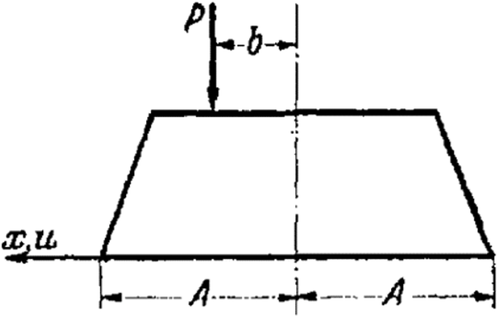
    This means a = A , while A is defined in Figure 7. Here, the equilibrium of moments requires
    A A p ( u ) u d u = P b . (36)
    Details are in the caption following the image
    Example (b)
    Elementary integration results in the conditional equation for α:
    π 4 E A 2 α = P b .
    Due to the fact that α 1 , we obtain the angle of rotation when we introduce the equivalent pressure p 0 = P / 2 A , as we will always want to do later:
    γ α = 8 π p 0 b E A . (37)
    If we take Equation (37) into account in Equation (35), we obtain the pressure distribution independent of E:
    p ( u ) = 2 p 0 π 1 u / A 2 1 + 2 b A u A . (38)

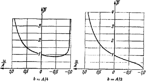
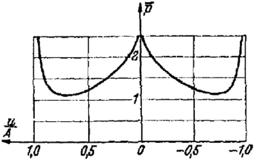
    The condition p 0 at the point u = A leads to the constraint b A / 2 . As long as this is satisfied, the bedplate does not lift from the substrate. Figure 8 shows the trend of the function p ¯ ( u / A ) p ( u ) π / ( 2 p 0 ) for b = A / 4 and b = A / 2 .

    Details are in the caption following the image
    Pressure distribution under an eccentrically loaded bed plate with a two-dimensional substrate
    2) For the case that a A . This is the case for b A / 2 . In the points u < a , the substrate and bedplate no longer have contact. The moment equation for point u = 0 (Figure 9), upon using Equation (35), is
    a a p ( u ) u d u = π 4 E α a 2 = P b ( A a ) . (39)
    Details are in the caption following the image
    Determining the pressure distribution for partial lifting of the bed plate from the ground
    Details are in the caption following the image
    Example (c)
    From this, we obtain
    p ( u ) = P π a 2 u 2 1 + 2 b ( A a ) a 2 u . (40)
    Since tension will initially occur at the point u = a , the conditional equation for a must be p ( a ) = 0 , meaning
    a = 2 ( A b ) . (41)
    With this, we obtain the following pressure distribution:
    p ( u ) = P π a a + u a u . (42)

    The curve p ( u ) · const is already drawn in Figure 8 ( b = A / 2 ). Here, u / a is only replaced with u / A . We note that also in this case, p ( u ) is independent of E.

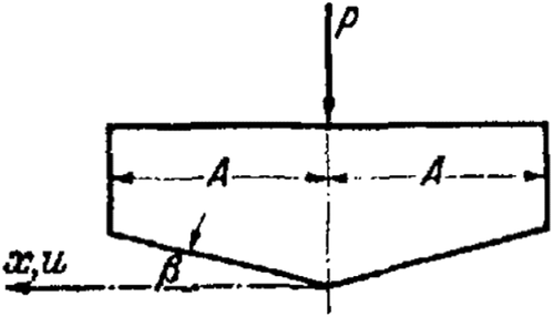
    (c) Cutting shape structure. Here, η x , 0 ( x ) = tan β = α for 0 x a . Due to symmetry, we use Equation (27) and have
    p ( u ) = 1 π a 2 u 2 P + E α 0 a x a 2 x 2 x 2 u 2 d x .
    The integral can be easily solved and one obtains
    p ( u ) = 1 π a 2 u 2 P E α a + E α π arctan 1 u a 2 . (43)

    Again, there are two cases to differentiate.

    1) P > E α A . In Equation (43), a = A must now be substituted. The pressure distribution is now dependent on the ratio p 0 : E :
    p ( u ) = 2 p 0 π 1 u A 2 1 / 2 1 E α 2 p 0 + E α 2 p 0 arctan 1 u A 2 . (44)

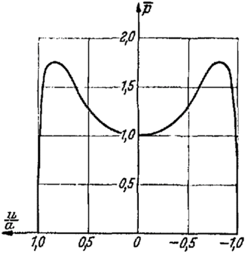
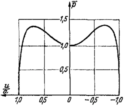
    Figure 11 illustrates this equation for the special case of p 0 = E α , p ¯ = π p ( u ) / ( 2 p 0 ) . Noteworthy is the fact that at the point u = 0 , p only becomes logarithmically infinite, while at the point u = A , the order of singularity is 1/2, as in example (a).
    Details are in the caption following the image
    Representation of the pressure distribution according to Equation (44)
    2) P E α A . So that p does not become negative, a A . In order to obtain p ( a ) = 0 , it is necessary to make the first term in Equation (43) identically equal to zero:
    a = P E α . (45)
    With this, the pressure under the wedge is obtained:
    p ( u ) = P π a arctan 1 u a 2 . (46)

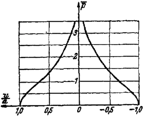
    Figure 12 depicts the trend of the function p ¯ = a π p ( u ) / P . In the middle, the pressure is logarithmically infinite. At the edges, the dependence of pressure is of such a low order that the tangents of the pressure distribution curve run asymptotically vertically.
    Details are in the caption following the image
    Pressure under the wedge

    Now, a geometrically sharp point would practically not exist; the point would be more or less rounded so that the pressure would not be infinite. To illustrate this, three simple examples will be examined that are also important from another view point.
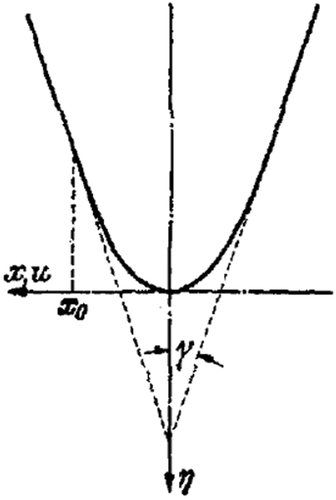
    (d) Parabolically rounded wedge. For a rounded profile according to a second order parabola (Figure 13)
    η x , 0 ( x ) = cot γ x x 0 for | x | x 0 .
    Details are in the caption following the image
    Parabolically rounded wedge
    Details are in the caption following the image
    Pressure distribution under a fourth order parabolic cylinder
    Details are in the caption following the image
    Pressure distribution under a sixth order parabolic cylinder
    Furthermore, we assume that a x 0 . Then, Hamel's method provides
    p ( u ) = 1 a 2 u 2 P π + E cot γ 4 x 0 ( a 2 2 u 2 ) . (47)
    The condition p ( a ) = 0 provides
    a = 2 x 0 P π E cot γ = 2 r 0 P π E . (48)
    Here, r0 is the radius of curvature of the parabola at the point x = 0 . With Equation (48), Equation (47) is simplified to
    p ( u ) = 2 P π a 1 u a 2 . (49)

    The Hertzian solution for the pressure is given by Equation (48) and Equation (49), which was to be expected. This is because in the derivation of the Hertzian formula, the loading structure is replaced with a parabolic cylinder with the same curvature along the contact line. However, the application of the Hertzian formula is only allowed for a r 0 . In our case, this restriction is unnecessary.

    For a > x 0 , nothing substantially new is provided. For the curvature of a fourth order parabola,
    η x , 0 ( x ) = cot γ x x 0 3 for | x | x 0 .
    With this at a x 0 , we obtain
    p ( u ) = 1 a 2 u 2 . P π + E cot γ 16 x 0 3 ( a 4 + 4 a 2 u 2 8 u 4 ) . (50)
    The condition p ( a ) = 0 yields
    a = 2 x 0 3 P 3 π E cot γ 4 (51)
    and, thus,
    p ( u ) = 4 P 3 π a 1 + 2 u a 2 1 u a 2 . (52)

    Whereas one could have immediately written the formula from Hertz for the previous case, this is not possible here, because the curvature of the profile disappears at the point of contact (flat point).

    If one chooses a sixth order parabola as the curve at the rounded wedge, then the pressure distribution becomes
    p ( u ) = 6 P 5 π a 1 + 4 3 u a 2 + 8 3 u a 4 1 u a 2 (53)
    with
    a = 2 x 0 5 P 10 π E cot γ 6 . (54)
    Let us choose a specific example to allow for a comparison between the three cylinder pressures:
    P = 1 kg / cm E = 10 4 kg / c m 2 , x 0 = 1 cm , and γ = π 4 .
    One finds for
    • a second order parabola: p max = 56.5 kg/cm2, a = 0.011 cm,
    • a fourth order parabola p max = 5.2 kg/cm2, a = 0.114 cm,
    • a sixth order parabola p max = 2.8 kg/cm2, a = 0.243 cm.
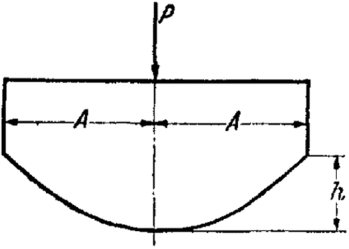
    (c) Parabolically-convex bedplate. The equations from Equation (47) to Equation (52) also describe the pressure distribution under a structure as that shown in Figure 16. The equation for the lower surface is
    η 0 ( x ) = h A 2 x 2 or η 0 ( x ) = h A 4 x 4 .
    Details are in the caption following the image
    Paraolically curved bed plate
    One substitutes 2 h / A 2 for cot γ / x 0 or 4 h / A 4 for cot γ / x 0 3 . Now, if according to Equation (48) or Equation (51) a A , then Equation (49) or Equation (52) apply. Otherwise, Equation (47) or Equation (50) provide the pressure distribution with a = A :
    p ( u ) = P π A 1 1 u A 2 1 + c 2 1 2 u A 2 with c 2 = π E h 2 P , (55)
    p ( u ) = P π A 1 1 u A 2 1 + c 4 1 + 4 u A 2 8 u A 4 with c 4 = π E h 4 P . (56)

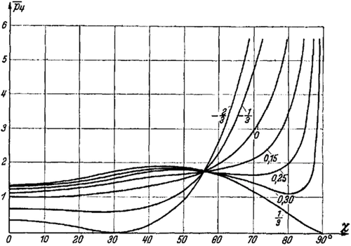
    So that p does not become negative, c2 and c4 must be constrained to the intervals 1 c 2 1 and 2 3 c 4 1 3 , respectively. Negative values for c2 and c4 are exhibited by concave bedplates.
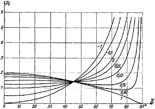
    The introduction of u = A sin χ in Equation (55) and Equation (56) serves to provide a clear graphical illustration (Figures 17, 18):
    p ( χ ) = P π A 1 + c 2 cos 2 χ cos χ = P π A p ¯ 2 ( χ ) , (55a)
    p ( χ ) = P π A 1 + 2 c 4 cos 2 χ c 4 cos 4 χ cos χ = P π A p ¯ 4 ( χ ) . (56a)
    Details are in the caption following the image
    Pressure distribution according to  Equation (55a)
    Details are in the caption following the image
    Pressure distribution according to  Equation (56a)

    Here, we would only like to draw attention to the importance of this pressure distribution for elastically supported, non-rigid structures. This question will be more generally addressed at a later point.
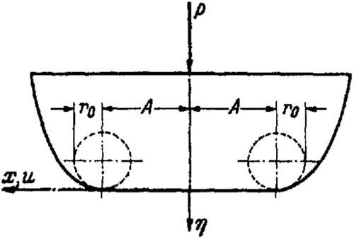
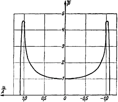
    (f) Flat bedplate with rounded corners. We consider the bedplate shown in Figure 19 and choose
    η x , 0 ( x ) = 0 for | x | A , η x , 0 ( x ) = | x | A r 0 for | x | A ,
    Details are in the caption following the image
    Bed plate with parabolically-rounded edges
    Details are in the caption following the image
    Pressure distribution for rounded edges
    where a is unknown. Equation (27) yields
    p ( u ) = 1 π a 2 u 2 P + E r 0 A a ( x A ) x a 2 x 2 x 2 u 2 d x . (57)
    For convenience, one may introduce the non-dimensional quantities
    x 1 = x A , u 1 = u A , a 1 = a A , r 1 = r 0 A (58)
    and then obtain
    p ( u 1 ) = 1 π a 1 2 u 1 2 P A + E r 1 1 a 1 ( x 1 1 ) x 1 a 1 2 x 1 2 x 1 2 u 1 2 d x 1 .
    Elementary integration yields
    p ( u 1 ) = 1 π a 1 2 u 1 2 P A + E 2 r 1 a 1 2 1 + ( a 1 2 2 u 1 2 ) π 2 arcsin 1 a 1 + ( u 1 1 ) a 1 2 u 1 2 ln a 1 2 u 1 + ( a 1 2 1 ) ( a 1 2 u 1 2 ) a 1 ( u 1 1 ) ( u 1 + 1 ) a 1 2 u 1 2 ln a 1 2 + u 1 + ( a 1 2 1 ) ( a 1 2 u 1 2 ) a 1 ( u 1 + 1 ) . (59)
    The equation p ( a 1 ) = 0 serves to determine a1:
    2 P r 1 A E = a 1 2 π 2 arcsin 1 a 1 a 1 2 1 . (60)
    This provides the pressure distribution
    p ( u 1 ) = E 2 π r 1 π 2 arcsin 1 a 1 a 1 2 u 1 2 + ( u 1 1 ) ln a 1 2 u 1 + ( a 1 2 1 ) ( a 1 2 u 1 2 ) a 1 ( u 1 1 ) ( u 1 + 1 ) ln a 1 2 + u 1 + ( a 1 2 1 ) ( a 1 2 u 1 2 ) a 1 ( u 1 + 1 ) . (61)
    Generally, the left side of Equation (60) becomes small with respect to 1. In this case, the only usable solution of the transcendental equation (Equation 60) is easy to find. One substitutes
    δ = a 1 2 1 a 1 , a 1 = 1 1 δ 2 (62)
    and, in doing so, Equation (60) becomes
    2 P r 1 A E = 1 1 δ 2 arcsin δ δ 1 δ 2 .
    If the left side is now small with respect to 1, then a 1 1 1 must be valid, also meaning that δ 1 . If one develops a series of powers of δ into 2 3 δ 3 2 15 δ 5 + · · · , then one may neglect the rest of the series with respect to the first term and find that
    δ = 3 P r 1 A E 3 = 6 p 0 r 1 E 3 with p 0 = P 2 A . (63)
    According to Equation (62)
    a 1 = 1 1 δ 2 1 + δ 2 2 = 1 + 1 2 6 p 0 r 1 E 2 / 3 , a = A 1 + 1 2 6 p 0 r 0 E A 2 / 3 . (64)
    In order to discuss Equation (61), one may differentiate it. One finds that the tangents of the curve run vertically at the points u = ± 1 , ± a 1 . Furthermore, we note that from Equation (57) p ( c ) < p ( d ) for 0 c < d 1 . From this, the fact is illuminated that the pressure distribution has a local minimum at u = 0 . In order to find the trend of the curve in the vicinity of u = a 1 , we introduce a new variable
    v = a 1 2 u 1 2 a 1 .
    In the vicinity of the point in question, v is of the same order of magnitude as δ. Developing a power series of Equation (61), with Equation (63) and Equation (64), yields
    p = 3 p 0 π δ v δ + 1 2 1 v 2 δ 2 ln δ + v δ v . (65)
    Through a quick calculation, one finds that
    p max = 3.6 p 0 π δ = 0.631 p 0 A r 0 · E p 0 3 . (66)

    The value p max occurs at a point that differs from ± a 1 only by a squared term of δ.

    Another representation is also important, namely, that obtained for 1 u 1 2 > 0 by developing a power series of the parameter δ. A somewhat cumbersome calculation yields
    p = 3 p 0 π δ 3 δ 3 2 3 1 u 1 2 + δ 5 10 13 u 1 2 ( 1 u 1 2 ) 3 / 2 + · · · . (67)
    If 1 u 1 2 δ , meaning we do not approach the vicinity of ±1, then we find the same pressure distribution as that of the bedplate without the rounded edges; because we suppress the terms of smaller order in this case so that
    p = 2 p 0 π 1 u 1 2 . (68)

    So, rounding the edges only affects the pressure distribution at the edges.

    In summary, we observe that if 2 P r 0 A 2 E 1 , then the pressure distribution near the edge is given by Equation (65), while away from the edge, Equation (68) may be used. In contrast, if the order of magnitude comparison 2 P r 0 A 2 E 1 is not valid, then one must resort to the strict formula of Equation (61) and determine a graphically from Equation (60).

    5. Examples for the axially-symmetric problem. Using Equation (28), Equation (32), and Equation (33), the associated pressure distributions for the respective axially-symmetric bedplates may be found for examples (a), (c), (d), and (e) by elementary integration. Let us be content with noting the results here.

    (a’) A flat bedplate.
    p ( ϱ ) = p 0 2 1 ϱ a 2 with p 0 = P π a 2 . (69)
    (c’) A conical bedplate.
    1 ) E α p 0 < 2 : p ( ϱ ) = p 0 1 4 1 ϱ A 2 1 / 2 2 E α p 0 + E α 2 p 0 arccos A ϱ with p 0 = P π A 2 . (70)
    Penetration occurs up to the edge.
    2 ) E α A 2 π P 2 : Cone pressure : p ( ϱ ) = P π a 2 arccos a ϱ with a = 2 P α π E . (71)
    (d’) A parabolic bedplate. Second order paraboloid of revolution (Figure 13):
    p ( ϱ ) = 3 P 4 π a 2 1 ϱ a 2 with a = 3 P x 0 4 E cot γ 3 ( Hertzian Formula ) . (72)
    Fourth order paraboloid of revolution:
    p ( ϱ ) = 5 P 6 π a 2 1 + 2 ϱ a 2 1 ϱ a 2 with a = 15 P x 0 3 16 E cot γ 5 . (73)
    Sixth order paraboloid of revolution:
    p ( ϱ ) = 7 P 10 π a 2 1 + 4 3 ϱ a 2 + 8 3 ϱ a 4 1 ϱ a 2 with a = 35 P x 0 5 32 E cot γ 7 . (74)
    (e’) Parabolically-convex bedplate. Let the cross-section be as that shown in Figure 16. Second order paraboloid of revolution:
    p ( ϱ ) = P 2 π A A 2 ϱ 2 1 + 2 3 c 2 c 2 ϱ A 2 with c 2 = 8 E h A P . (75)
    Fourth order paraboloid of revolution:
    p ( ϱ ) = P 2 π A A 2 ϱ 2 1 + 2 5 c 4 + c 4 ϱ A 2 2 c 4 ϱ A 4 with c 4 = 64 E h A 9 P . (76)

    The quantities c2 and c4 are to be limited to the interval 3 2 c 2 3 and 40 21 c 4 5 3 , respectively.

    (f’) Flat bedplate with rounded edges. Let the cross-section of the bedplate be defined according to Figure 19. The prescribed edge displacement is
    ξ 0 ( r ) = ( r A ) 2 2 r 0 for r A ξ 0 ( r ) = const = ξ 0 ( 0 ) for A r 0 . (77)
    Equation (28) provides
    Φ ( z ) = E ξ 0 ( 0 ) z r 0 z 2 A 2 π 2 A + A arcsin A z for z A , E ξ 0 ( 0 ) for z A . (78)
    With Equation (78) and Φ ( a ) = 0 , Equation (32) provides
    p ( ϱ ) = E π r 0 c a 2 s 2 A 2 A π 2 arcsin A s s 2 ϱ 2 d s with c = A for ϱ A , ϱ for ϱ A . (79)
    A more exact investigation of the pressure distribution, which is given by the integral presentation, especially the simple formulas for p max and a, is only possible for the case a A A . Then, namely, a s A for all values of s in both integration intervals of Equation (79). Therefore, we may substitute π 2 arcsin A s ( s A ) 2 1 , as done in Equation (60). With the dimensionless quantities
    s 1 = s A , ϱ 1 = ϱ A , a 1 = a A , r 1 = r 0 A (80)
    Equation (79) now reads
    p ( ϱ 1 ) = E π r 1 c 1 a 1 s 1 2 1 s 1 2 ϱ 1 2 d s 1 with c 1 = 1 for ϱ 1 1 , ϱ 1 for ϱ 1 1 . (81)
    First, we investigate the trend of p ( ϱ 1 ) in the vicinity of the point ϱ 1 = a 1 . If we consider that over the integration interval of Equation (81), s 1 1 1 , then we can take
    s 1 2 1 s 1 2 ϱ 1 2 = 2 ( s 1 1 ) ( 1 + ϱ 1 ) ( s 1 ϱ 1 )
    and find the following after elementary integration:
    p = E π r 1 2 1 + ϱ 1 ( a 1 1 ) ( a 1 ϱ 1 ) + 1 2 ( ϱ 1 1 ) ln a 1 1 + a 1 ϱ 1 a 1 1 a 1 ϱ 1 . (82)
    Let a 1 ϱ 1 = v 1 and a 1 1 = ε 1 . Developing a power series for Equation (82) yields
    p = E ε 2 π r 1 v ε + 1 2 1 v 2 ε 2 ln ε + v ε v . (83)
    The function within the parentheses has already been seen in Equation (65). We note that d p d ϱ 1 when ϱ 1 1 and ϱ 1 a 1 . Furthermore, for ϱ A
    p ( ϱ ) = E π r 0 A a s 2 A 2 s 2 ϱ 2 d s E π r 0 A a s 2 A 2 s 2 A 2 d s = E ( a A ) π r 0 . (84)
    A comparison between Equation (83) and the results of example (f), shows that the maximum pressure is assumed to be along a circle that has a radius that differs from a by only a small second order value. This pressure is
    p max = 1.2 E ( a A ) π r 0 . (85)
    In order to finally determine a, we do not use Equation (33) this time, but rather draw support in the fact that within a certain circle, which must be A ϱ a A , the pressure distribution is the same as for the two-dimensional bedplate. For a ϱ sufficiently satisfying the immediately preceding conditions, the following is valid:
    p = P 2 π A A 2 ϱ 2 = p 0 2 1 ϱ 1 2 . (86)
    With a 1 1 = ε 2 , we go to Equation (81) for ϱ 1 1 and obtain
    p ( ϱ 1 , ε ) = E π r 1 1 1 + ε 2 s 1 2 1 s 1 2 ϱ 1 2 d s 1 . (87)
    According to Taylor's theorem
    p ( ϱ 1 , ε ) = p ( ϱ 1 , 0 ) + ν = 1 ε ν ν ! ν ε ν p ( ϱ 1 , ε ) ε = 0 . (88)
    Here, p ( ϱ 1 , ε ) is defined by the integral. For this reason, p ( ϱ 1 , 0 ) = 0 . The quantity p / ε is found from Equation (87) to be
    ε p ( ϱ 1 , ε ) = E π r 1 2 ε a 1 2 1 a 1 2 ϱ 1 2 with a 1 = 1 + ε 2 . (89)
    Further differentiation yields
    2 ε 2 p ( ϱ 1 , ε ) = E π r 1 2 a 1 2 1 a 1 2 ϱ 1 2 + 4 a 1 ε 2 1 ϱ 1 2 ( a 1 2 ϱ 1 2 ) 3 / 2 a 1 2 1 ,
    3 ε 3 p ( ϱ 1 , ε ) = E π r 1 4 ( 1 ϱ 1 2 ) ( a 1 2 ϱ 1 2 ) 3 / 2 a 1 + 1 3 a 1 2 a 1 2 1 + a 1 + 2 ε 2 2 3 a 1 2 1 ϱ 1 2 a 1 2 ϱ 1 2 .
    For ε = 0 , meaning a 1 = 1 ,
    p ε ε = 0 = 0 , 2 p ε 2 ε = 0 = 0 , 3 p ε 3 ε = 0 = E 4 2 π r 1 1 ϱ 1 2 .
    We insert this into Equation (88) and neglect terms that are small with respect to the first non-neglected term. In this way, we obtain
    p = 2 2 E ε 3 3 π r 1 1 ϱ 1 2 . (90)
    Comparison with Equation (86) yields
    ε = 3 π r 1 p 0 4 2 E 3 . (91)
    So
    a 1 = 1 + ε 2 = 1 + 3 π r 1 p 0 4 2 E 2 / 3 or a = A 1 + 3 π 4 2 r 0 A p 0 E 2 / 3 . (92)
    Furthermore, according to Equation (85) and Equation (92)
    p max = 0.537 p 0 A r 0 p 0 E 3 with p 0 = P π A 2 . (93)

    The dependence of pressure on radius is given in the following way: For all ϱ not in the vicinity of A, the trend of p is presented by Equation (86). In the vicinity of ϱ = A , which continues to ϱ = a , we use Equation (83). The pressure assumes its largest value along a circle having a radius that differs from a by only a small second order value.

    By appropriately choosing the radius of the rounded edge, as was seen in Equation (93) similarly to the two-dimensional problem, we may reduce the maximum pressure to one below the proportionality limit of the bedplate so that we are sure to be able to calculate the described pressure distribution. This is practically applicable for the transfer of force through steel bodies to wood or cement substrates. For bedplates on earthen substrates, the requirement of complete isotropic elasticity of the bedplate can only be approximately satisfied for certain types of substrate. The value of p max calculated from Equation (93) or Equation (66) is incidentally an upper limit for the pressure under an elastic structure on an elastic substrate, if the bedplate sinks more in the middle than at the edge.

    6. Pressure distribution beneath flexible structures. The calculation of the pressure distribution under an elastic bedplate on an elastic isotropic substrate involves considerable difficulties. Even for a known pressure distribution, it is only possible to specify the displacement of the contact surface for very few bedplate geometries, such as beams, plates, and slabs. Here, on the contrary, one must present this displacement as a function of the unknown surface load, in order to set them equal to the corresponding values of the bedplate interface. Linear equations in which the unknown pressure function is presented in differential, integral, or series form must then be solved. One would try to execute this using an iteration technique or series ansatz. Borowicka conducted to the latter in a simple case for a plate.

    Now, in most cases, depending on the pressure distribution, one would be able to know from the beginning whether a bedplate sinks more in the middle than at the edges. Let us then consider as a first approximation two-dimensional and three-dimensional bodies that are composed of a linear combination of parabolas or paraboloids of revolution of second, fourth, etc. order. The corresponding pressure distributions can be taken from examples (e) or (e’), respectively, in connection with Equation (66) and Equation (93), which gives the upper limit for the maximum pressure as long as the middle of the bedplate sinks more than the edges. The opposite case should be avoided. Deviation of the approximate pressure distribution from reality is so large for very elastic beams or plates that the approximation is too crude. In contrast, for appropriately constructed bedplates (e.g., square plates or cylindrical indenters with sufficient height) one may use these approximations very well.

    7. Summary. For a given pressure distribution over the contact surface between a bedplate and a substrate, the two-dimensional and axially-symmetric problem of perpendicular displacement of the contact surface may be presented using simple integral expressions. Inverse transformations were developed for these expressions, which allow for the pressure distribution to be calculated from a prescribed displacement. Thereby, the task of discovering the pressure distribution under a rigid bedplate with an arbitrary contact surface in both the two-dimensional case and the axially-symmetric case is generally solved. Several practically important examples show the usefulness of these considerations. Above all, the conclusions may be drawn for the pressure distribution under an elastic bedplate.

    (Received on March 23, 1942.)

    • 1 Dissertation at the Technische Hochschule München (D 91) in a shortened edition (Examiner: Prof. Dr. L. Föppl and Prof. Dr. J. Lense).
    • 2 L. Föppl, Forsch. Ing.-Wes. 12 (1941) p. 31.
    • 3 Okubo, Z. Angew. Math. Mech. 20 (1940) p. 271.
    • 4 Compare with p. 33 in L. Föppl, Forsch. Ing.-Wes. 12 (1941) p. 31.
    • 5 G. Hamel, Integralgleichungen, Berlin (1937) p. 145.
    • 6 Compare with Frank-Mises, Die Differential- und Integralgleichungen der Mechanik und Physik, Bd. 1, pp. 483–485, 2. Aufl., Braunschweig (1930).
    • 7 Compare with p. 34 in L. Föppl, Forsch. Ing.-Wes. 12 (1941) p. 31.
    • 8 E. Mathieu gave a solution to the boundary value problem of the plane elasticity theory for the rectangle: E. Mathieu, Théorie de l’Élasticité des Corps solides, S. 140, Paris (1890).
    • 9 Borowicka, Ing.-Arch., 10 (1939) p. 113.

    The full text of this article hosted at iucr.org is unavailable due to technical difficulties.