Water-Soluble Organic Dyes as Efficient Anode Interlayer Materials for PEDOT:PSS-Free Inverted Bulk Heterojunction Solar Cells
Abstract
Solution-processed inverted organic solar cells (OSCs) generally use poly(3,4-ethylenedioxythiophene):poly(styrenesulfonate (PEDOT:PSS) as hole selective anode interlayer (AIL). However, the acidic nature of PEDOT:PSS considerably accelerates the degradation dynamics of OSCs, which shortens the durability of these low-cost photovoltaic devices. Small organic molecules are attracting growing interest as alternative AIL materials, but their solubility limited to toxic organic solvents hinders the production of environmentally friendly OSCs. Herein, the first inverted OSCs employing non-PEDOT:PSS solution-processed top small organic molecule AILs deposited from aqueous solution are reported. The investigated water-soluble spirobifluorene (SBF) derivatives 1 and 2 show hole mobility (≈4 × 10⁻³ cm2 V−1 S−1) higher than PEDOT:PSS. Because of their nonacidic nature, the interlayers formed with derivatives 1 or 2 considerably delay the degradation of the top metal electrode compared to OSCs employing PEDOT:PSS interlayers. The PEDOT:PSS-free OSC devices with inverted configuration with the water-soluble SBF derivatives as AIL produce power conversion efficiencies above 5% with PTB7-Th:ITIC active layers and above 8% with PBDB-T-2Cl:Y6 active layers, respectively, with an enhancement up to 28% compared to OSCs employing PEDOT:PSS. These results correspond to the highest reported values for PEDOT:PSS-free small-molecule inverted OSCs deposited from an aqueous solution.
1 Introduction
The rising interest in polymer-based organic solar cells (OSCs) over the past decade can be easily explained by the major technological advantages they present over conventional photovoltaics (PVs). For instance, OSCs can be fabricated at a low cost through high productivity roll-to-roll processes, which enables the facile manufacturing of large-area flexible devices. Owing to the development of highly efficient conjugated polymer donors and non-fullerene acceptors, polymeric OSCs now demonstrate certified power conversion efficiencies (PCEs) over 17%.[1] However, further improvements are needed to move from laboratory research to a large diffusion of devices in society.[2] OSCs can be broadly classified into two categories: conventional and inverted architectures. Independent of the device architecture, the OSCs are built by sandwiching the photoactive materials between two electrodes. In both configurations, the addition of cathode and/or anode interlayers (AILs) plays a pivotal role in the enhancement of the device performance due to better energy level alignment and improved charge collection at the interfaces.[3] For these reasons, designing novel organic interface materials has become an important part of the OSC field.[4] In particular, the development of compounds that can be deposited by printing or coating is essential to move toward all solution-processed ultralow-cost devices.
Due to its ability to efficiently transport holes while blocking electrons, poly(3,4-ethyelenedioxythiophene):poly(styrenesulfonate) (PEDOT:PSS) is currently the state-of-the-art interface material to reduce leakage currents at the active layer/anode interface.[5] However, some drawbacks are limiting the performance of devices employing this material. Indeed, PEDOT:PSS works quite well for conventional architecture OSCs, but when it comes to inverted ones (i.e., deposited directly on the active layer) wetting becomes a major issue. A possible alternative explored in the past years has been the addition of surfactants such as Triton-X[6] or Zonyl FS-300,[7] which has a positive impact in solving the wetting issue. Nevertheless, this approach requires a precise formulation of the PEDOT:PSS dispersion, and the uniformity of the results (i.e., the reproducibility) is usually much lower than that of the evaporated interlayers, such as molybdenum oxide (MoO3). In addition, due to the potential dewetting effects of the hygroscopic PEDOT:PSS interlayer caused by the presence of water in the air,[7] the acidity of PEDOT:PSS can lead to device stability issues, especially when used in combination with metal electrodes and/or flexible substrates.[8] For these reasons, developing alternative materials to replace PEDOT:PSS is an essential step to ensure that durable organic electronic devices can be manufactured at an ultralow cost.
Another important feature that the current research aims to solve prior to upscaling and commercialization of the OSCs is the reduction of the amount of toxic solvents (such as chlorinated compounds) employed during the fabrication process. Water-/alcohol-soluble conjugated organic polymeric or small molecular interlayers have commonly been regarded as the best options for interfacial materials because of their unique properties, such as easy-to-implement solution processing using environmentally friendly solvent and orthogonal solubility with the active layer materials.[9] Recently, many small molecules showing solubility in alcoholic solutions have been reported as cathode interlayer materials,[4, 10] while less literature can be found on innovative non-polymeric AIL materials, especially in inverted devices.[11] The ideal AIL should satisfy three main requirements: i) modulate the work function of the anode to match the highest occupied molecular orbital (HOMO) of the donor, ii) show good optical transmittance, and iii) possess decent hole mobility and low electron mobility to promote selective hole collection at the interface between the active layer and the anode. Owing to their good hole mobility and tunable energy level, p-type organic small molecules are ideal alternative materials to PEDOT:PSS for environmentally friendly AIL fabrication. Nevertheless, only a few examples of small molecules showing solubility in alcoholic solution have been reported,[4, 12] while the use of the aqueous solution for the deposition of non-polymeric AIL is very rare.[13] It is also important to mention that some alternatives to PEDOT:PSS as top AIL have been previously proposed, but the only successful material (phosphomolybdic acid) leading to efficient (PCE > 5%) OSC fabrication is as corrosive or more corrosive than PEDOT:PSS.[14]
In the past years, 3D structural compounds are attracting attention as efficient materials for OSCs.[15] Among them, spirobifluorene (SBF) derivatives represent an interesting class of molecules due to their peculiar features.[16] As a highly twisted and π-conjugated skeleton, SBF has been widely applied as the conjugated core to reduce the anisotropic and non-uniform characteristics of thin films, and the molecules designed by this strategy have achieved much success in different optoelectronic applications.[17] The most known SBF derivative in the energy conversion field is the 2,2’,7,7’-tetrakis-(N,N-di-4-methoxyphenylamino)-9,9’-spirobifluorene (Spiro-OMeTAD), which was first used by Grätzel as solid-state hole transport layer material in dye-sensitized solar cells,[18] and lately applied successfully to perovskite solar cells.[19] However, Spiro-OMeTAD mostly dissolves in the solvents used for OSC active layer deposition, which hinders the possibility of depositing it as solution-processed AIL on top of the active layers in inverted OSCs. Surprisingly, despite the huge molecular design effort to find alternative small-molecule AILs processable with environmentally friendly solvents,[20] the use of green-solvent-processable SBF derivatives has yet to be explored.
Based on our long experience on the specific modification of the SBF core,[21] we recently reported the synthesis of the SBF-based compound 1 showing exceptionally high solubility in water and alcohol.[22] The presence of sulfonate groups ensures its solubility in the aqueous solution and suggests analogies with the pH-neutral polyelectrolyte employed in polymeric OSCs.[23] With the aim of increasing the palette of p-type organic small molecules for the modulation of anode interface, we designed a novel dye that was highly soluble in water and alcohols, showing cross-shape configuration, low absorption in the visible range, and enhanced hole mobility due to the presence of two triphenylamine units.
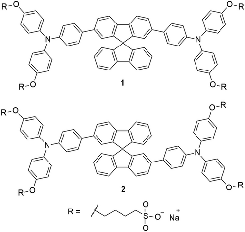
Herein, we report the synthesis of the novel SBF derivative 2, which is the isomer of dye 1, and the performance of the OSC devices with inverted configuration built by replacing the PEDOT:PSS with the two different water-soluble isomers 1 and 2 (Figure 1).
2 Results and Discussion
2.1 Synthesis
Dye 2 was obtained following the same approach reported for dye 1 (see Scheme S1 and the Supporting Information for the experimental details and characterization). The first step is the preparation of the SBF core bearing two halide atoms in positions 2 and 2’, i.e., the 2,2’-diiodo-9,9'spirobifluorene (3). This intermediate was obtained starting from 2,2’-dinitro-9,9’-spirobifluorene (4),21, 24 which was reduced to give the diamino compound (5) by using tin chloride (SnCl2 hydrate) as a reducing agent, followed by Sandmeyer's reaction, as previously reported by Lützen et al.[25] However, by following the synthetic procedure described in the paper, we were unable to reach the previously reported good yield of the diiodo compound (72%). Instead, we obtained the desired product in a relatively low yield of 27%. After several attempts, we observed that heating the reaction mixture after the addition of potassium iodide for 2 h remarkably increased the yield (63%) to values close to the reported one. As the heating of the reaction after the addition of the iodine salt is described as a standard procedure of the Sandmeyer's reaction to promote the release of nitrogen as gas, we think the previously reported procedure was missing an essential part.
Afterward, the synthesis of compound 2 followed the same strategy as the one used for the preparation of compound 1, i.e., Suzuki coupling between 3 and 4-(N,N-di(4-methoxyphenyl)amino)phenylboronic pinacol ester (6) to give the intermediate 7, followed by deprotection via treatment with boron tribromide (BBr3) (8) and subsequent alkylation with 1,4-butanesultone in the presence of sodium hydride. Both compounds 1 and 2 were obtained by precipitation.
2.2 Optoelectronic Properties of AILs
Both isomers have been deeply investigated in solution and solid state. The absorption spectra of 1 and 2 recorded in water (Figure 2a) reflect the different conjugation lengths of the two isomers. These experiments reveal the lack of electronic conjugation between the two fluorene units in the ground state of 2. This results in an absorption spectrum centered in the UV range and a 26 nm hypsochromic shift of the lower energy band absorption maximum from 378 nm for 1 to 352 nm for 2. Interestingly, the same behavior was observed in solid state (Figure 2b), indicating that the electronic properties of the molecules are preserved after deposition by spin-coating.
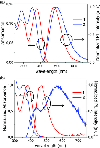
The emission spectra of the investigated dyes show a different behavior, both in solution and in solid state (Figure 2). In solution, the extended conjugation of 1 caused an intense photoluminescent emission with a maximum of 480 nm, which can also be observed in the solid-state measurements. The emission peak of 2 in an aqueous solution is at 494 nm, while after spin-coating, we observed a weak double band emission covering the entire visible range.
As mentioned earlier, alignment of the HOMO energy levels of the electron donor and the AIL, as well as ohmic contact at the AIL/anode interface, will be a key factor to ensure efficient hole collection at the anode. In this study, we selected PTB7-Th as the electron donor, which is coupled with ITIC, a non-fullerene acceptor, in the active layers. The molecular structures of PTB7-Th and ITIC can be found in Figure 3 along with an energy diagram of the inverted OSC architecture employed in this study. The HOMO levels (measured by photoelectron yield spectroscopy or PYS, Figure S7, Supporting Information) of PTB7-Th, PEDOT:PSS, compound 1, and compound 2 have values of 4.98, 5.01, 5.32, and 5.33 eV, respectively. In other words, as the HOMOs of PTB7-Th and PEDOT:PSS have similar values, we can certainly expect to form ohmic contacts at the PTB7-Th/PEDOT:PSS interfaces. In contrast, the HOMOs measured for the newly synthesized compounds lie approximately 0.3 eV below the PTB7-Th HOMO. According to previous research, the empirical limit to form ohmic contacts across interfaces involving organic semiconductors is 0.3 eV.[26] As a result, despite the relatively large 0.3 eV gap, holes can still be injected from PTB7-Th into some of the energy disordered states of the SBF derivative AILs. Nevertheless, the more adequate band alignment between PTB7-Th and PEDOT:PSS compared to that between PTB7-Th and compounds 1 or 2 should result in more efficient charge extraction at the PTB7-Th/PEDOT:PSS interface with respect to the PTB7-Th/SBF derivative ones. However, as the SBF derivatives can collect holes with lower energy than those collected by PEDOT:PSS or bare ITO, the open-circuit voltage (Voc) values for the OSCs prepared with compounds 1 or 2 should be higher than those obtained for no interlayer OSCs or those employing PEDOT:PSS AILs.[27] Note that, although we focus our study on PTB7-Th-based active layers as a proof of principle, the general trend in the field of OSCs to achieve high PCEs is to use PBDB-T derivatives, such as PBDB-T-2F or PBDB-T-2Cl, as electron donor combined with non-fullerene acceptors such as Y6 in the active layers (see molecular structure in Figure S8, Supporting Information).[28] According to literature, the HOMO of PBDB-T lies at −5.33 eV,[29] while those of the well-known halogenated derivatives of PBDB-T have even lower values around −5.47 and −5.52 eV for PBDB-T-2F[30] and PBDB-T-2Cl,[31] respectively. The deeper HOMO levels of compounds 1 and 2 with respect to PEDOT:PSS suggest that they may be more suitable than PEDOT:PSS for the manufacturing of next-generation all-solution-processed efficient inverted OSCs employing PBDB-T derivatives as electron donors. To reduce detrimental leakage currents and increase the OSC photovoltaic performance, the AILs should also act as electron blocking layers. For that purpose, the lowest unoccupied molecular orbital (LUMO) level of the interlayer materials should be significantly higher than the electron acceptor's LUMO, which is generally below −3.8 eV.
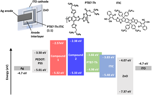
Here, we calculate the LUMO values for compounds 1 and 2 from their HOMOs and their optical bandgaps, which were estimated as the energy of the absorption spectra edges with values of 2.75 and 2.95 eV for compounds 1 and 2, respectively. It is worth emphasizing that AILs with large optical bandgaps could contribute to avoiding exciton quenching by the anode through the exciton blocking effect, resulting in better performance of OSC devices. The resulting LUMOs for compounds 1 and 2 thus lie at 2.57 and 2.38 eV, respectively. Note that these values are significantly above the LUMOs of PTB7-Th and ITIC, suggesting that electrons should be efficiently blocked at the active layer/AIL interfaces.[32] To limit leakage current in the devices, the ideal AIL should also demonstrate high hole mobility and low electron mobility, respectively. We determined the charge mobility for compounds 1 and 2 through space-charge-limited current (SCLC) measurements from unipolar devices. The hole mobility values obtained were 4.1 × 10⁻³ and 3.5 × 10⁻³ cm2 V−1 S−1 for compounds 1 and 2 (Figure S9, Supporting Information). These values are one order of magnitude higher than Spiro-OMeTAD,[33] i.e., the highly employed hole transporting material for solar cells, and comparable with the hole mobility measured in similar SBF-based amines soluble only in organic solvents,[34] indicating that the lateral chains are not affecting the hole conduction properties of the molecules. Moreover, the measured hole mobility values are around one order of magnitude higher than those recently reported for PEDOT:PSS.[35] Both compounds also display low values of electron mobility of 4.2 × 10⁻⁸ and 6.6 × 10⁻¹⁰ cm2 V−1 S−1 for compounds 1 and 2, respectively, thus confirming the potential that these SBF derivatives have when it comes to efficient hole collection.
2.3 Formation of AIL Layers onto the PTB7-Th:ITIC Active Layers
The synthesized SBF-based AILs demonstrate high solubility in polar solvents such as ethanol (EtOH) and water. Although water is the ideal solvent when it comes to green processing of top AIL layers, depositing a water-based solution or dispersion onto a highly hydrophobic active layer can become quite challenging. As EtOH readily wets the surface of hydrophobic active layers, it shows great potential as a processing solvent for the AIL we developed here. The toxicity of EtOH toward the human body or the environment is much lower than that of organic solvents commonly employed for OSC fabrication, such as chlorobenzene or methanol (MeOH). This low toxicity and low hazard aspect represent a major advantage when it comes to the industrial fabrication of OSCs. It is worth noting that the use of EtOH or water/EtOH is quite limited also in the field of polymeric AILs, which are more often deposited from the more toxic MeOH,[36] MeOH/acetic acid,[37] or MeOH/water solutions.[38]
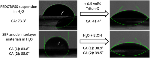
To verify which polar solvent or solvent mixture can be employed to process SBF derivative top hole transport layers for inverted OSC architectures, we first measured the contact angles (CAs) of various AIL solutions and PEDOT:PSS suspensions deposited on the surface of PTB7-Th:ITIC active layers (Figure 4). Note that similar results were obtained for both SBF derivatives, but the images in Figure 4 correspond to compound 1. The large CAs obtained for the aqueous solutions of compound 1 or 2 deposited on the PTB7-Th:ITIC active layers (>80°) confirm that forming continuous AIL layers from purely aqueous solutions is highly unlikely. However, using a 1:1 mixture of water and EtOH considerably reduces the CAs to values below 40°, which should enable the formation of AIL thin films onto the active layer. These values are equivalent to those obtained for PEDOT:PSS suspensions after the addition of 0.5 vol% of Triton-X.
The proper wetting of the PTB7-Th:ITIC active layers does not guarantee the formation of high-quality interlayers, especially when considering that typical interlayer thicknesses are relatively small (<20 nm). Thin films of compound 1 or 2 with thicknesses around 10–15 nm can be deposited on ITO substrates by spin-coating the water:EtOH (1:1) mixed solvent solutions at 2000 rpm.
To verify whether SBF derivative films are formed under the same spin-coating conditions when deposited on top of the active layers, we performed a systematic study using X-ray photoelectron spectroscopy (XPS) of active layers before and after spin-coating the AILs. The chemical formula of PTB7-Th and ITIC exhibit relatively high carbon to oxygen (C:O) ratios of 49:2 and 94:2, respectively. In comparison, the two newly synthesized compounds have relatively low C:O ratios of 77:16. Note that, among all the AILs employed in this study, PEDOT:PSS has the lowest C:O ratio with values of 6:2 and 8:3 for PEDOT and PSS, respectively. Successful formation of AIL layers on top of the active layers should thus result in a decrease in the C:O ratio at the sample surface, which can be probed with XPS (O1s and C1s peaks). The C:O ratios calculated from the C1s and O1s peaks (Figure S10, Supporting Information) are summarized in Table 1.
| C:O ratios | Surface roughness (min/max) [nm] | |||
|---|---|---|---|---|
| PTB7-Th:ITIC/AIL | AIL only | RMS | Rz | |
| PTB7-Th:ITIC | 28.2 | – | 0.49/0.64 | 4.21/7.94 |
| PEDOT:PSS | 3.5 | 3.6 | 2.18/3.57a) | 18.0/28.4a) |
| Compound 1 | 18.4 | 4.4 | 0.38/0.59a) | 2.17/4.02a) |
| Compound 2 | 15.2 | 4.4 | 0.29/0.43a) | 1.75/3.44a) |
- a) Data from PTB7-Th:ITIC/AIL bilayers.
The C:O ratio measured at the surface of the active layer/PEDOT:PSS bilayer has a similar value to that of PEDOT:PSS thin films deposited directly on the substrate. The small discrepancy between the two values could be arising from minor changes in the relative concentration of PSS at the surface of the films. We should keep in mind that PEDOT:PSS dispersions are three to four times more concentrated than the SBF derivative solutions, which results in relatively thick PEDOT:PSS layers (>50 nm) when deposited on ITO substrates at 2000 rpm. In contrast, using 5 × 5 μm2 area atomic force microscope (AFM) images (Figure S11, Supporting Information), we found that the maximum peak to valley height (Rz) of the PTB7-Th:ITIC active layer surface is between 4 and 8 nm (Table 1). As XPS probes the surface properties of thin films up to 5–10 nm, our results clearly indicate that relatively thick PEDOT:PSS layers (>20 nm) are successfully formed on top of the active layers when deposited from aqueous dispersions with Triton-X as added surfactant. However, the AFM images, as well as the large increase in Rz values upon PEDOT:PSS coating, clearly indicate that the active layers are not covered by a uniform PEDOT:PSS layer. In fact, the root mean square (RMS) of the surface roughness increases from 0.5 to above 2 nm upon coating the PTB7-Th:ITIC active layers with PEDOT:PSS. The formation of non-uniform AILs could be detrimental to charge collection in inverted OSCs.
In contrast, when the PTB7-Th:ITIC active layers are coated with thin interlayers of compound 1 or 2, the resulting RMS and Rz values are lower than those of the bare active layers. The larger decreases in RMS and maximum Rz observed when employing compound 2 compared to compound 1 suggest that a more uniform active layer coverage is obtained with the second isomer. This hypothesis is confirmed by the lower C:O measured for PTB7-Th:ITIC/compound 2 bilayers compared to that of PTB7-Th:ITIC/compound 1 bilayers, which take values of 15.2 and 18.4, respectively (Table 1). Spin-coating the mixed solvent solutions of SBF derivatives on ITO substrates at 2000 rpm results in thin films with thicknesses of approximately 12 nm. Despite being significantly lower than the C:O of PTB7-Th:ITIC thin films (28.2), the C:O of PTB7-Th:ITIC/SBF derivative bilayers are still well above 4.4, the C:O value of 12 nm thick SBF derivative films deposited directly onto ITO substrates. Considering the Rz values of PTB7-Th:ITIC active layers and the probing depth of XPS, it is safe to assume that the relatively high C:O ratios observed in PTB7-Th:ITIC/compound 1 or 2 bilayers result from the partial detection of the underlying active layer materials. In fact, the O1s peaks of the active layer/AIL bilayers in Figure S10, Supporting Information, exhibit contributions from both the active layer and compound 1 or 2. These results suggest that the AIL formed on the PTB7-Th:ITIC active layers is thinner than the AILs formed directly on ITO substrates. Nevertheless, these AILs should be sufficiently thick to observe an impact on the OSC performances, in particular, on their Voc.
2.4 PV Properties of OSCs Fabricated with Various AILs
Table 2 and Figure 5 summarize the PV properties of PTB7-Th:ITIC OSCs fabricated without AIL and with PEDOT:PSS, compound 1, or compound 2 as AIL. The reported values are obtained by averaging the parameters measured for eight different devices for each configuration.
| AIL | J sc [mA cm−2] | V oc [V] | FF [%] | PCE [%] | PCEmax [%]a) | R s [Ω·cm2] | R sh [Ω·cm2] |
|---|---|---|---|---|---|---|---|
| None | 14.9 ± 0.2 | 0.55 ± 0.02 | 44.7 ± 2.6 | 3.70 ± 0.14 | 3.82 | 6.46 ± 0.49 | 203 ± 23 |
| PEDOT:PSS | 15.2 ± 0.7 | 0.66 ± 0.01 | 50.4 ± 4.8 | 5.05 ± 0.16 | 5.21 | 2.60 ± 0.36 | 435 ± 43 |
| Compound 1 | 15.4 ± 0.3 | 0.70 ± 0.00 | 49.7 ± 2.1 | 5.31 ± 0.23 | 5.48 | 2.40 ± 0.55 | 543 ± 66 |
| Compound 2 | 15.5 ± 0.3 | 0.69 ± 0.00 | 50.3 ± 1.8 | 5.42 ± 0.23 | 5.65 | 2.55 ± 0.45 | 871 ± 98 |
- a) Data of the best device.
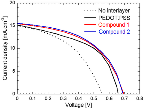
The impact of AIL insertion at the active layer/Ag electrode interface can be clearly seen independent of the material employed for the interlayer. The decrease in leakage current is well reflected in the increasing shunt resistance (Rsh) of the devices employing interlayers, and the increase in Rsh is well correlated with the observed short-circuit current density (Jsc) increase. The Jsc values measured from the current density–voltage (J–V) characteristics are also well correlated with the values obtained by integrating the incident photon-to-current conversion efficiency (IPCE) spectra for all devices (Figure S12, Supporting Information). Furthermore, no spectral change could be observed in the IPCE spectra, which indicates that there is neither undesired absorption from the interlayer material, nor energy transfer from the AILs to the active layer materials.
These results and observations suggest that the increase in Jsc can be mostly attributed to the interlayer's capacity to efficiently block electrons. The lower electron mobility of compound 2 with respect to compound 1 further explains the large difference in Rsh observed in devices employing these two AILs. Recent studies have shown that PEDOT:PSS exhibits ambipolar charge transport properties and that the intrinsic electron mobility in PEDOT:PSS thin films could actually be higher than their hole mobility.[39] This might explain the lower Rsh measured for PEDOT:PSS devices with respect to the OSCs fabricated with other AILs. In contrast, similar series resistance (Rs) values are obtained for all devices employing interlayers, which could suggest that even in the case of SBF derivatives, continuous thin layers are successfully formed on top of the active layers. Nonetheless, a slightly lower fill factor (FF) is obtained with compound 1 with respect to compound 2 or PEDOT:PSS. As compounds 1 and 2 demonstrate similar hole mobility values, it is highly probable that compound 1 does not cover the active layer as uniformly as compound 2.
As expected, a significant increase in Voc is observed upon insertion of the interlayer for all three AILs. The Voc increases from 0.55 V for the OSCs without interlayer to 0.66, 0.70, and 0.69 V for devices fabricated with PEDOT:PSS, compound 1, and compound 2 interlayers, respectively. As predicted, as the HOMO levels of SBF derivatives lie deeper than the PEDOT:PSS HOMO, slightly larger Voc values are obtained with compounds 1 and 2 compared to that of PEDOT:PSS OSCs. The increase in Voc upon insertion of interlayers is associated with enhanced FF, resulting in PCEs significantly higher than that of the no interlayer devices. The maximum average PCE value of 5.42% is obtained with compound 2 interlayers. This corresponds to 46% and 7% PCE increases in comparison with the no AIL and PEDOT:PSS AIL control devices, respectively.
As suggested earlier, the low-lying HOMOs of compounds 1 and 2 could be beneficial when it comes to fabricating OSCs based on PBDB-T-2Cl, an electron donor with a HOMO level lying at −5.52 eV. The energy difference at the PBDB-T-2Cl/SBF derivative interface is of approximately 0.2 eV, suggesting that an ohmic contact at the interface between the two materials should be formed. Note that, as the PEDOT:PSS HOMO level (−5.01 eV) is higher than that of PBDB-T-2Cl, holes can still be collected across the PBDB-T-2Cl/PEDOT:PSS interface, but less efficiently than when employing SBF derivatives. These hypotheses correlate well with the initial results we obtained using PBDB-T-2Cl:Y6 active layers (Table 3). The Voc obtained with the SBF derivatives (0.67 V) is significantly higher than those produced by OSCs without AIL (0.55 V), and slightly above those measured from OSCs with PEDOT:PSS AILs (0.65 V). The FF of the SBF derivative devices are also notably higher than those of the PEDOT:PSS or no AIL OSCs, and reach values around 56% and 54% with compounds 1 and 2, respectively. The resulting average PCEs for devices fabricated with compounds 1 and 2 reach values of 8.13% and 7.72%, respectively. In contrast, the PEDOT:PSS OSCs only exhibit an average PCE of 6.34%. Unlike the PTB7-Th:ITIC OSCs, higher PV performance is obtained with compound 1 compared to compound 2 in the PBDB-T-2Cl:Y6 OSCs. These opposite trends could arise from the difference in surface free energy of the PTB7-Th:ITIC and PBDB-T-2Cl:Y6 active layers, and suggest that further optimization may be necessary to achieve even higher PCEs using the SBF derivatives we developed here, which is beyond the aim of this study.
| AIL | J sc [mA cm−2] | V oc [V] | FF [%] | PCE [%] | PCEmax [%]a) |
|---|---|---|---|---|---|
| None | 21.4 ± 1.2 | 0.55 ± 0.02 | 36.6 ± 1.1 | 4.32 ± 0.16 | 4.44 |
| PEDOT:PSS | 21.4 ± 0.7 | 0.65 ± 0.01 | 45.7 ± 4.8 | 6.34 ± 0.71 | 7.05 |
| Compound 1 | 21.6 ± 0.4 | 0.67 ± 0.00 | 56.2 ± 1.3 | 8.13 ± 0.20 | 8.33 |
| Compound 2 | 21.3 ± 0.2 | 0.67 ± 0.01 | 54.1 ± 0.7 | 7.72 ± 0.08 | 7.79 |
- a) Data of the best device.
It is worth emphasizing that the PCE values measured for compounds 1 and 2 are among the highest values reported for p-type small organic molecules used in OSCs as AILs fabricated from nontoxic solutions (Table S1, Supporting Information).[40] Higher values have been reported for non-polymeric AILs deposited from MeOH.[41] Evaporated interlayers (e.g., MoO3) yield higher PCEs around 6.8% (12.3% in the case of PBDB-T-2Cl:Y6 active layer) thanks to larger FF, which indicates that better coverage of the active layer could further enhance the device performance of OSCs fabricated with solution-processed top interlayers. In fact, the non-uniform active layer coverage by PEDOT:PSS could partially explain why the OSCs using PEDOT:PSS AILs do not exhibit FF significantly higher than the OSCs employing the SBF derivatives and their low-lying HOMOs.
2.5 Stability of Inverted OSCs Employing Various AILs
The stability of the organic layers and durability of the PV devices are still a big concern in the emerging field of OSCs.[42] In addition to photooxidation of the active materials, several studies suggest that the presence of acidic layers such as PEDOT:PSS considerably fastens the degradation dynamics of the metal electrodes.[8, 43] Unlike small organic molecules, PEDOT:PSS is often considered to be thermally stable. To compare the thermal stability of the various AILs, we exposed unencapsulated PTB7-Th:ITIC OSCs prepared without and with AILs to mild annealing at 100 °C for 15 min, 30 min, 45 min, 1 h, 2 h, 3 h, and 24 h. The normalized values reported in Figure 6 are obtained by averaging the parameters measured for eight different devices for each configuration.
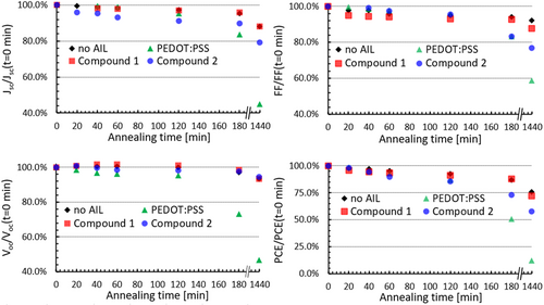
After 1 h of annealing at 100 °C, the average PCE of the OSCs prepared with no AIL, PEDOT:PSS, compound 1, and compound 2 decreases by 4.8%, 7.0%, 6.7%, and 10.4%, respectively. These minor differences between the various devices are not significant enough to draw conclusions, but some different trends in Jsc can already be clearly observed. In particular, OSCs fabricated with compound 2 exhibit a large decrease in Jsc during the first hour, which is the principal cause for their initial 10% PCE drop. In contrast, the decrease in PCE for OSCs employing PEDOT:PSS and compound 1 can be associated with drops in Voc and FF, respectively. After 3 h of annealing, the differences between the various OSCs become more obvious, and these differences are even more notable after 24 h of annealing. After 24 h of annealing, the average PCE of OSCs produced with PEDOT:PSS drops dramatically by 90%, while the other devices exhibit a much lower decrease of 40% (compound 2) or even less (without AIL and compound 1) in their average PCE. The trends for the OSCs prepared without AIL and those prepared with compound 1 are essentially the same, and these two types of OSCs correspond to the most stable among the four studied architectures. These results suggest that, despite being a small organic molecule, compound 1 is stable under mild temperature annealing conditions. OSCs prepared with compound 2 exhibit slightly faster degradation dynamics as compared to compound 1, which could be caused by the tendency of compound 2 to aggregate as suggested by the emission spectrum in Figure 2. Note that the temperature employed for our study is above the temperature generally used for accelerated OSC durability tests, namely 85 °C.[44]
After 3 h of annealing, we can observe a rapid deterioration of all PV parameters for OSCs prepared with PEDOT:PSS, even if it is often regarded as being stable in air. This might suggest that the large decreases in PV parameters for the PEDOT:PSS OSCs are related to corrosion of the top Ag electrodes, which are in direct contact with the strongly acidic PEDOT:PSS layer. In fact, the PEDOT:PSS formulation employed in our study has a pH of 1.6 as opposed to the almost neutral nature of compound 1 and 2 solutions (pH = 7–8). To verify the acidic PEDOT:PSS layer-induced corrosion hypothesis, we monitor the sheet resistance of Ag electrodes deposited onto compound 1 or PEDOT:PSS AILs stored in air for up to 2 weeks. Both PEDOT:PSS/Ag and compound 1/Ag have similar average sheet resistance values in their pristine state. These values are 0.64 and 0.67 Ω cm−2 for the samples using PEDOT:PSS and compound 1, respectively. After 1 week of storage, the values increase to 0.77 and 0.70 Ω cm−2 for PEDOT:PSS/Ag and compound 1/Ag samples, respectively. In other words, even when maintained at room temperature in air, the electrodes placed in contact with PEDOT:PSS exhibit a 21% increase in sheet resistance, while those deposited on compound 1 maintain a sheet resistance within 5% of the initial value. These differences in trend are further emphasized after 2 weeks of storage. In fact, compound 1/Ag samples maintain a constant sheet resistance value (0.70 Ω cm−2), and PEDOT:PSS/Ag samples exhibit a 27% increase in sheet resistance (0.81 Ω cm−2).
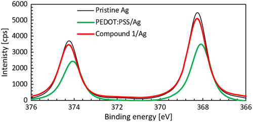
The redox reaction occurring at the Ag/PEDOT:PSS interface should result in the formation of oxidized Ag species. These species can be monitored by comparing the Ag3d peaks in the XPS spectra of PEDOT:PSS/Ag and compound 1/Ag samples stored in air for 2 weeks with the spectrum of pristine Ag (Figure 7). According to literature, oxidation of Ag results in notable decreases in the Ag3d peak intensities associated with a 0.4 eV shift of the Ag3d5/2 peak toward lower binding energies.[45] The XPS spectra presented in Figure 7 correlate well with our hypothesis about the increase in sheet resistance caused by accelerated oxidation of Ag in contact with the acidic PEDOT:PSS layer. In fact, after being stored 2 weeks in air, PEDOT:PSS/Ag samples exhibit a notable shift in binding energy and a significant decrease in peak intensity with respect to pristine Ag. This is in contrast with the behavior observed in the compound 1/Ag samples, which show a slight decrease in peak intensity without shift. These observations suggest that only minor oxidation occurs in these samples. Note that the fresh PEDOT:PSS/Ag and compound 1/Ag samples produce very similar peak intensities and binding energies as the pristine Ag sample. Finally, we should emphasize here that the XPS data only corresponds to oxidation occurring on the surface of the 65 nm thick Ag layers and that more significant differences between the samples should be found in the bulk of the Ag layers or at the AIL/Ag interfaces.
3 Conclusion
We reported the full characterization of two novel small molecules designed by combining SBF with triphenylamine derivatives. The polar substituents on the triphenylamine derivatives enable the solubilization of these new compounds into nontoxic solvents such as water and EtOH. Owing to their good hole mobilities and solubility in polar solvents, the synthesized materials can be employed as top AILs processed from environmentally friendly solutions. As their solutions in EtOH/water mixtures readily wet the OSC active layers, these pH neutral compounds have the potential to solve the degradation and wettability issues associated with the commonly employed AIL, namely PEDOT:PSS. The reported data on PTB7-Th:ITIC OSCs show that replacing PEDOT:PSS AILs with thin films of compounds 1 or 2 slightly improves the photovoltaic performance leading to a PCE enhancement of 7% compared to the PEDOT:PSS-based device. Interestingly, the data obtained using compounds 1 and 2 in combination with a different active layer, namely PBDB-T-2Cl:Y6, lead to PCE values exceeding 8%, with an enhancement of PV performance exceeding 28% compared to the PEDOT:PSS-based OSCs. These observations emphasize the versatility and efficiency of the newly designed compounds employed as top AILs replacing the acidic PEDOT:PSS in OSCs. Our study also confirms that the OSCs employing the SBF derivatives synthesized here demonstrate higher stability than the devices prepared with PEDOT:PSS when annealed at 100 °C for up to after 24 h. Despite being small molecules, the SBF derivatives exhibit similar thermal stability as PEDOT:PSS, and their nonacidic nature results in slower Ag electrode oxidation dynamics compared to the electrodes deposited on PEDOT:PSS. In summary, we report the first OSCs employing non-PEDOT:PSS solution-processed top small organic molecule AILs deposited from the aqueous solution that produce PCEs above 8%. Although further optimization and studies are necessary to improve the performance of the devices, the SBF derivatives here reported represent an important step for the development of durable all-solution-processed environmentally friendly OSCs, and thus play a pivotal role toward the mass production of low-cost printable OSCs.
4 Experimental Section
Synthesis
Experimental details for the preparation and characterization of SBF derivatives 1 and 2 are given in the Supporting Information.
Characterization of AIL Materials and Active Layer Materials
UV–Vis measurements were performed on a Jasco V-750 double-beam spectrophotometer and baseline corrected. Extinction molar coefficients were calculated by interpolation of data obtained from five solutions. Steady-state emission and excitation spectra were recorded on an FLS920 (Edinburgh Instruments) fluorescence spectrometer equipped with a single grating monochromator in both the excitation and the emission sides, and coupled to an R928P Hamamatsu photomultiplier; a 450 W Xe arc lamp was used as the excitation source. The emission spectra were corrected for detection and optical spectral response of the fluorescence spectrometer through a calibration curve supplied by the manufacturer.
PYS measurements were performed using a photoelectron spectrometer (AC-2, Riken Keiki) in ambient air conditions. Monochromatic ultraviolet light was irradiated onto the sample at an incident angle of 30° from the sample surface. The photon energy was scanned from 4.2 to 6.2 eV, and the maximum number of photons was set to 6.3 × 10¹⁰ photons/s at 5.8 eV. The photoelectrons emitted from the sample surface were collected and counted using a cylindrical open counter placed above the sample surface in ambient air conditions.[46] The PY spectra were obtained by dividing the number of photoelectrons by the number of incident photons. XPS was measured using a Jeol JPS-9200 equipped with an Mg Kα X-ray source.
All AFM images and cross sections were collected in contact mode. CA measurements were performed using a system built in-house consisting of a monochromatic light source, a high-resolution camera, and an adjustable sample stage. To obtain a precise value of the CAs, the data were analyzed using ImageJ with a plug-in developed and provided by the Biomedical Imaging Group of the Ecole Polytechnique Fédérale de Lausanne.[47]
Solid-state samples were prepared by spin-coating solutions of interlayer or active materials onto quartz (optical spectroscopy) or glass/ITO (photoelectron spectroscopy) substrates cleaned through the following procedure. The substrates were sequentially sonicated in acetone, Semico Clean (Furuuchi Chemicals), water, and isopropanol. After being exposed to isopropanol vapors to eliminate any solvent traces, remaining organic contaminants were removed with an ultraviolet ozone surface cleaner (Ossila). Compounds 1 or 2 were deposited from 5 mg mL−1 solutions in a 1:1 EtOH:water solvent mixture at 2000 rpm for 60 s typically leading to film thicknesses around 12 nm. A quantity of 0.5 vol% of Triton-X (Sigma-Aldrich) was added to the PEDOT:PSS (Clevios P VP AI 4083, Heraeus) suspension, which was then coated at 2000 rpm for 60 s onto the substrates to produce 50 nm thick PEDOT:PSS films. PTB7-Th films of 40 nm thickness were fabricated by spin-coating a 10 mg mL−1 solution in chlorobenzene onto cleaned substrates.
Device Fabrication and Characterization
Glass/ITO substrates were cleaned following the procedure described earlier. They were then coated by spin-coating a zinc oxide (ZnO) precursor solution made by mixing zinc acetate dihydrate (100 mg mL−1) and ethanolamine (2 vol%) into 2-methoxyethanol at 3000 rpm for 40 s. The precursor thin film was then annealed at 200 °C for 30 min, followed by slow cooling to form a compact electron transporting ZnO layer with a thickness between 30 and 50 nm. The aforementioned chemicals and the solvents employed in this section were purchased from Sigma-Aldrich without further purification, while PTB7-Th and ITIC were acquired from Luminescence Technology. The PTB7-Th:ITIC active layer solution was produced by blending the donor and the acceptor in chlorobenzene with a 1:1.3 ratio and a total concentration of 20 mg mL−1. The solution was spin-coated at 1500 rpm for 60 s to form approximately 90 nm thick active layers. PBDB-T-2Cl and Y6 were purchased from Ossila Ltd and blended in a 1:1 ratio in chloroform containing 0.5 vol% of 1-chloronaphthalene with a total concentration of 16 mg mL−1. The PBDB-T-2Cl:Y6 active layers were produced by spin-coating the aforementioned solution onto the ITO/ZnO substrates at 6000 rpm for 60 s. The active layers were then coated with the PEDOT:PSS suspension or the compound 1 or 2 solutions at 2000 rpm for 60 s. The substrates were then placed into a high vacuum (<10−4 Pa) overnight to ensure complete removal of the solvent before evaporating 65 nm thick Ag anodes to finalize the inverted OSC architecture. The overlap of the ITO cathode and Ag anode defines an active area of 0.04 cm2 for each OSC.
The photovoltaic parameters of the OSCs were obtained by measuring the J–V characteristics of the devices exposed to a 1 sun (AM1.5G, 100 mW cm−2) illumination. The provided data corresponds to the average from eight different OSCs prepared under the same conditions. IPCE was measured using a Peccell PEC-S20 measurement system. The data presented in Figure S4, Supporting Information corresponds to the average of two OSCs.
For the stability measurements, eight OSCs with an active area of 0.04 cm2 for each type of AIL were annealed at 100 °C in the air up to 24 h. Their PV characteristics were measured after 0 min, 20 min, 40 min, 1 h, 2 h, 3 h, and 24 h of annealing. The average PV parameters from eight OSCs for each type of AIL were then normalized to the parameters at t = 0 min (pristine state). To evaluate the oxidation states of the Ag electrodes placed in contact with the various AILs, the sheet resistance of 65 nm thick Ag electrodes deposited on glass/AIL substrates was measured with a four-point probe system from Astellatech (SR4-S) coupled with a Keithley 2100 source meter right after electrode deposition (pristine Ag) as well as after 1 and 2 weeks stored in air at room temperature. The data presented in the manuscript corresponds to the average value of 4 measurements performed on each of the three 2 × 0.5 cm2 Ag electrodes prepared for each AIL. Ag oxidation was also monitored by comparing the XPS spectra of pristine Ag with those of Ag deposited on ITO/AIL substrates and kept in the air at room temperature for 2 weeks.
Acknowledgements
V.V. thanks the Izumi Science and Technology Foundation for the financial support. F.R. thanks Prof. B.J. Ravoo for fruitful discussion.
Open access funding enabled and organized by Projekt DEAL.
Conflict of Interest
The authors declare no conflict of interest.
Open Research
Data Availability Statement
Research data are not shared.


