4D Cell-Condensate Bioprinting
Abstract
4D bioprinting techniques that facilitate formation of shape-changing scaffold-free cell condensates with prescribed geometries have yet been demonstrated. Here, a simple 4D bioprinting approach is presented that enables formation of a shape-morphing cell condensate-laden bilayer system. The strategy produces scaffold-free cell condensates which morph over time into predefined complex shapes. Cell condensate-laden bilayers with specific geometries are readily fabricated by bioprinting technologies. The bilayers have tunable deformability and microgel (MG) degradation, enabling controllable morphological transformations and on-demand liberation of deformed cell condensates. With this system, large cell condensate-laden constructs with various complex shapes are obtained. As a proof-of-concept study, the formation of the letter “C”- and helix-shaped robust cartilage-like tissues differentiated from human mesenchymal stem cells (hMSCs) is demonstrated. This system brings about a versatile 4D bioprinting platform idea that is anticipated to broaden and facilitate the applications of cell condensation-based 4D bioprinting.
1 Introduction
Since it was first introduced by Tibbits from the Massachusetts Institute of Technology in 2013,[1] four-dimensional (4D) printing,[2] as a newly emerging technology platform built on the well-known three-dimensional (3D) printing (also referred to as additive manufacturing, AM),[3] has received rapidly increasing research interest in the last few years due to its enormous application prospects in a myriad of fields including soft robotics,[4] actuators,[5] flexible wearable electronics,[6] and biomedical engineering.[7] Similar to 3D printing, 4D printing relies on the selection of materials, printer, and mathematical modeling and design.[8] However, since 4D printing adopts specifically smart materials that respond to external stimuli (e.g., light,[9] moisture,[10] temperature,[11] electric fields,[12] and magnetic fields[13]) through a change in the macroscopic morphology,[14] an additional time dimension is integrated with the 3D printing to endow the printed architecture with the ability to undergo spatiotemporal shape transformation,[15] affording constructs with more sophisticated configurations,[16] and more importantly, enabling the capability to reshape over time in accordance with practical needs.[17] As such, 4D printing shows a clear advantage over 3D printing for tissue regeneration-related applications, where time-dependence is an important consideration for recapitulating the structural evolution of conformationally intricate tissues during maturation.[18]
4D bioprinting involves the use of biocompatible materials and incorporation of viable cells[19] to fabricate bioactive cell-laden constructs (bioconstructs) capable of dynamic reconfiguration.[20] The built-in dynamism in bioprinted 4D bioconstructs together with the complex, tailorable geometries brings huge potential in biomimetic 4D tissue engineering. For 4D bioprinting, the smart materials, material processing, and stimulation must be strictly cytocompatible to maintain viability of incorporated cells.[21] Even though a variety of materials such as alloys,[22] ceramics,[23] liquid crystal elastomers,[24] composites,[25] and shape-memory polymers[26] have been widely utilized to date in 4D printing, they generally fail to meet the demands of live-cell encapsulation.[27] In this regard, given that hydrogel scaffolds can provide a soft tissue-like environment to support cell growth,[28] efforts have been dedicated to developing hydrogel-based materials that allow for shape change under physiological stimulation for 4D bioprinting.[29, 30] For example, hollow self-folding tubes were fabricated using alginate and hyaluronic acid-derived hydrogels,[31] and gelatin and polyethylene glycol-based hydrogels were employed to fabricate a 4D physiologically adaptable patch to treat myocardial infarction.[32] An alginate/polydopamine composite was used as cell-laden bioink to fabricate near-infrared-triggered shape-morphing constructs.[33] In a recent study, 4D digital light printed silk hydrogels were applied as implants for treatment of a damaged trachea.[34] We also developed a series of biopolymer-based[35] and microgel-based bioinks[36] as versatile bioprinting platforms.
Despite inspiring preliminary achievements in 4D bioprinted cell-laden hydrogels, the scaffold-based approach often encounters the difficulty of synchronizing hydrogel degradation with the new tissue formation,[37] presents potential cytotoxicity originating from the fabrication techniques and degradation byproducts,[38] and strongly restricts the cell-to-cell interactions that are important during tissue development and healing.[39, 40] In comparison, scaffold-free, cell condensation-based alternatives exclude the use of scaffolding materials for individual cell encapsulation to yield a tissue construct that can readily circumvent the above limitations.[41] Taking the importance of shape transformations and remodeling during tissue formation into consideration, the development of a cell condensation construct that bears programmable deformation capability after fabrication is of great significance. Nonetheless, a system with this capability has not been demonstrated yet.
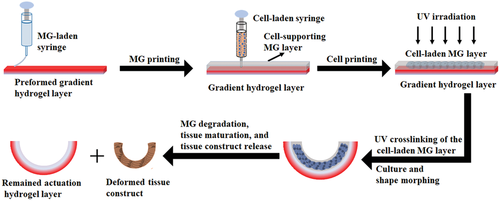
To address this challenge, a 4D cell-condensate bioprinting strategy using a unique bilayered system has been developed in this work to impart the shape-morphing feature to a 3D printed cell construct (Scheme 1). The proposed bilayer consists of a preformed gradient-crosslinking hydrogel layer as the actuation layer that drives the shape morphing and a printed photocurable and degradable cell-supporting microgel (MG) layer that allows printing a cell-only bioink inside and maintains the shape of the printed cells as they form a condensate in the initial stage. Upon the gradual and controllable degradation of the photocrosslinked MG layer during culture in tissue-specific differentiation media, 4D transformation into a mature tissue with a well-defined configuration can be obtained on demand.
2 Results and Discussion
2.1 Cell-Free Bilayer Fabrication and Shape-Morphing Behaviors
We have previously demonstrated the feasibility of incorporation of a UV absorber into a single-component photocrosslinkable biopolymer, such as an oxidized and methacrylated alginate (OMA, Figure S1a, Supporting Information), to effectively generate a crosslinking gradient throughout the hydrogel thickness by a one-step UV photocrosslinking (Figure S1c, Supporting Information),[35] which is attributed to UV absorber-based light attenuation along the light pathway.[42] Consequently, an internal anisotropic strain was generated after swelling in media, leading to hydrogel deformation (Figure S1c, Supporting Information). Herein, a bicomponent photocrosslinkable biopolymer composite of O5M45A (OMA with 5% theoretical oxidation and 45% theoretical methacrylation) and methacrylated gelatin (GelMA) (Figure S1b, Supporting Information) was employed to form a gradient hydrogel [O5M45A/GelMA(g)]. While the bicomponent hydrogel without gradient formation (O5M45A/GelMA) exhibited a similar modulus with the single-component non-gradient hydrogel (O5M45A), the elastic modulus of O5M45A/GelMA(g) was smaller than that of O5M45A(g) (Figure 1a). Since the modulus of the gradient hydrogels is determined by the “soft part” with less crosslinking extent (low-crosslinking side), the bottom side of the O5M45A/GelMA(g) hydrogel as shown in Figure S1c (Supporting Information) could be less crosslinked than that of O5M45A(g) hydrogel, which implies that O5M45A/GelMA(g) had a larger gradient range in comparison with the single-component gradient hydrogel [O5M45A(g)]. As a result, this bicomponent gradient hydrogel exhibited greater deformability (Figure S2, Supporting Information).
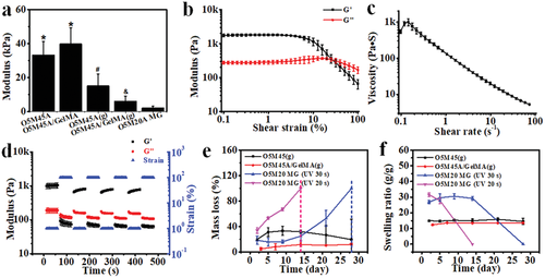
The printability of O5M20A MGs, which are calcium ion (Ca2+)-crosslinked hydrogels fabricated according to our previously described method (Experimental Section),[43] was then studied prior to the bilayer hydrogel fabrication. The prepared MGs behaved as a stable bulk hydrogel under low shear strains, (Figure 1b and Figure S3a, Supporting Information) but yielded at a shear strain over 25% (Figure 1b). Shear-thinning behavior was also identified by increasing the shear rate (Figure 1c), shear strain (Figure S3b, Supporting Information), and shear stress (Figure S3c, Supporting Information). Moreover, the MGs displayed a rapid and reversible phase transition between the solid-like (elastic) state and the liquid-like (viscous) state by alternating the shear strain applied between 1% and 100% (Figure 1d and Figure S3d, Supporting Information), suggesting favorable extrudability and rapid self-healing after deposition.[43, 44] Consequently, MG structures matching the digital models were readily printed and further stabilized by subsequent UV-crosslinking (Figure S4, Supporting Information), resulting in dual-crosslinked constructs. As expected, due to the low methacrylation degree, the MGs exhibited a rapid and tunable degradation profile in cell growth media. For example, the dual-crosslinked MG completely degraded in 14 days (pink line) when UV-crosslinked for 20 s, while it took ≈28 days for complete degradation if the MGs were UV irradiated for 30 s (blue line) (Figure 1e). This result provides evidence that the liberation of a cell condensation construct at a predetermined time point may be accomplished by simply adjusting the UV-crosslinking time. In addition, the UV-crosslinked MGs also exhibited a higher swelling ratio (Figure 1f) but much weaker mechanics (Figure 1a) than the non-MG gradient hydrogels at the initial stage, and the swelling and mechanics decreased along with the degradation over time (Figure 1f and Figure S5, Supporting Information). In contrast, the O5M45A/GelMA(g) was relatively stable in the media during the course of a 28-day culture. The higher stability of the proposed O5M45A/GelMA(g) actuation layer can provide a stable shape-morphing force to maintain the shape of the deformed cell construct for long-term culture.
Owing to its printability and photocrosslinkability, the O5M20A MGs can be finely printed using a 22-gauge needle (inner diameter 0.41 mm) onto the surface of a pre-fabricated O5M45A/GelMA(g) substrate (Movie S1, Supporting Information). The printing of O5M20A MGs benefits better reproducibility and reduced material waste. The printed MG layer was subsequently UV-crosslinked, forming a stable bilayer system with robust interfacial adhesion between the two layers (Figure 2a,b, and Figure S6, Supporting Information) through the covalent crosslinking of the remaining methacrylate groups on the preformed O5M45A/GelMA(g) surface (Figure S7, Supporting Information) with the methacrylate groups on the O5M20A MG.[45] Although the as-crosslinked MGs exhibited a higher swelling ratio than the O5M45A/GelMA(g) hydrogel (Figure 1f), this bilayer hydrogel (i.e., a disc) rapidly rolled into a tubular structure toward the MG side when immersed in the phosphate buffered saline (PBS, pH 7.4) media (Figure 2c and Movie S2, Supporting Information), due to a synergistic contribution of (i) the large gradient within the actuation layer that generates a substantial actuation force large enough to overcome the opposite layer strain brought by the swelling discrepancy and (ii) the extremely weak stiffness of the MG layer that allows easy deformation. The role of the actuation layer in driving the shape-morphing process was further verified by a comparison experiment (Figure S8, Supporting Information). Among hydrogel strips tested, including single-layer non-gradient O5M45A/GelMA, gradient O5M45A/GelMA and MG hydrogels (Figure S8a−c, Supporting Information) and bilayer hydrogels (Figure S8d,e, Supporting Information) with a non-gradient or gradient O5M45A/GelMA layer, only the hydrogels with a gradient layer showed remarkable rolling, while the shapes of the hydrogels involving no gradient remained unchanged. Interestingly, the bilayer that consisted of an MG layer and a non-gradient O5M45A/GelMA (Figure S8d, Supporting Information) did not show any shape change despite the swelling difference between the two layers. This is because the MG layer is too soft to serve as either an actuation layer or a shape-constraint layer. For this reason, the bilayer composed of an MG layer and a gradient O5M45A/GelMA layer shared a comparable bending angle with the single-layer gradient hydrogel (Figure S8f, Supporting Information). This exquisite design offers a unique bilayer system in which the two layers have specific, independent functions.
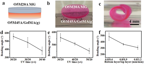
The prototype of the bilayer hydrogel strip was then used to investigate the impact of UV crosslinking time exposed to each layer (the gradient layer and the MG layer) and the thickness of the MG layer on shape-morphing behavior. Results of the quantified bending angles revealed a clear influence of these parameters on the hydrogel deformation (Figure 2d,e). Increasing UV exposure time and MG layer thickness both exerted negative effects on the hydrogel bending. As far as the UV time, the receiving time for each layer can be selectively tuned to control the hydrogel bending. For example, the UV time for the upper layer (MG layer) can be adjusted after being deposited onto the preformed gradient layer (Figure 2d and Figure S9a, Supporting Information) or the UV time can be adjusted when fabricating the bottom layer (gradient layer) while fixing the UV time for the upper layer (Figure 2e and Figure S9b, Supporting Information). The lowered bending arose from the combined outcome of reduced gradient range and lowered volumetric swelling by increasing UV time.[34] Differing from the UV time, the lowered bending achieved by the increasing MG thickness (Figure 2f and Figure S9c, Supporting Information) can be mainly attributed to increased resistance of the MG layer to the morphing. This controllable shape-morphing property will benefit applications where the capacity to tailor the extent of geometric change is desirable.
2.2 Cell Condensate-Laden Bilayers Fabrication and Their Shape-Morphing Behaviors
The printability of the live cells within the MG layer was examined before fabricating the cell condensate-laden bilayer system. Live cells themselves can serve as a cell-only bioink[43] to be printed into an O5M20A supporting MG bath, which was first printed as described above. In this cell-only printing process, the supporting material is typically shear-thinning and rapidly self-healing,[43, 44] permitting free embedding and deposition of live cells by replacing the MGs along the needle moving pathway and concurrently maintaining the printed cell construct with high fidelity. After printing, the dual-crosslinkable property of the MGs enables UV crosslinking to further stabilize the printed cell-only bioink and permits cell condensation formation without an intervening scaffold material. HeLa cells were first printed into a cell filament with a 25-gauge needle (inner diameter 0.26 mm) inside an as-printed MG strip (22 × 5 × 1 mm3). The cell filament-laden MG strip was subsequently UV crosslinked and imaged under a microscope to examine the printing resolution and then cultured in cell-growth media for 4 h to examine the cell viability. Results showed that the cells were printed into a filament with a uniform diameter distribution (Figure S10, Supporting Information), confirming reliable cell printability, and remained highly viable (Figure 3a), suggesting no obvious adverse effects of the bioprinting process and UV crosslinking on cell survival. Next, larger cell constructs with common shapes (e.g., a cell slab, 18 × 4 × 1.2 mm3, Figure 3b, left and middle images), a cell sheet (13 × 13 × 1.2 mm3, Figure 3b, right image, and Figure S11, Supporting Information), and a cell cuboid (5 × 5 × 4 mm3, Figure S12, Supporting Information) were printed into the supporting MG bath, further confirming the cell printability.
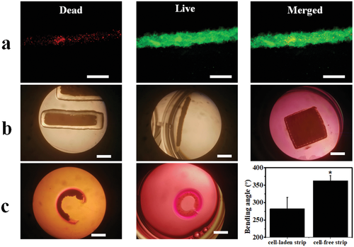
Cell condensate-laden bilayer hydrogel strips were then fabricated by a sequential printing process (30 s/20 s UV crosslinking time) and the shape-morphing behaviors were recorded. The O5M20A MG strip (22 × 5 × 1.2 mm3) was first printed onto the surface of a preformed O5M45A/GelMA(g) hydrogel disc and cells were subsequently printed within the MG layer to form a cell strip-laden bilayer construct (Movie S3, Supporting Information), which was then UV crosslinked. Cell condensate-laden bilayer constructs were then obtained by cutting from the large construct and cultured in cell growth media for 4 h, which was the time when no further morphological changes could be observed. As expected, the cell-laden bilayer strip underwent a bending process into a letter “C” shape toward the cell-laden layer side (Figure 3c, left) with, however, a smaller bending angle in comparison to the cell-free bilayer strip (Figure 3c, middle and right), most likely due to enhanced morphing resistance by the infilled cell condensate. Noteworthily, the shape-morphing process did not compromise the integrity of the printed cell construct because of the firm support by the surrounding dual-crosslinked MGs.
2.3 Printing of Large Cell Constructs with Complex Structures and Their Shape-Morphing Behaviors
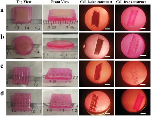
The successful 4D bioprinting of the bilayer cell condensate-laden hydrogel strips inspired printing of larger cell condensate-laden constructs with more complex structures and investigation of their shape-morphing behaviors. Four different bilayer bioconstructs, including sheet-based bilayers with a cell filling in the shape of a sheet, bar grid, and net, and a disc-based bilayer with a disc-shaped cell infilling, were fabricated with a similar sequential printing process described above (Figure 4, 40 s/20 s UV crosslinking time). HeLa cells were printed into specific geometries within the MG layer, and these self-transformable cell condensate-laden and cell-free constructs morphed into concave structures by curling up to the cell layer side after culturing in cell growth media for 4 h. In addition, these bioconstructs appeared to be less curled compared to their cell-free counterparts, in agreement with the results obtained from the bilayer hydrogel strips. The above results collectively demonstrated the feasibility and effectiveness of this strategy to fabricate cell condensates with prescribed configurations by the 4D bioprinting technique.
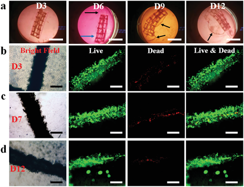
To assess the long-term cell viability and stability of the bioconstructs, the cell-net infilled bilayer sheet (Figure 4d) was cultured in cell growth media, cell viability was examined using a live/dead staining assay, and shape changes were monitored over a course of 14 days (Figure 5). The curling of the bioconstruct progressively increased during the first few days of culture (before day 5, Figure S13, Supporting Information) due to MG layer degradation-induced softening of the cell-laden layer (Figure S5, Supporting Information). The overall structure remained in a cylindrical shape, and the printed cells went through condensation to reinforce the “cell-net filament” during this period. It is interesting to note that the two layers (i.e., the actuation layer and cell condensate-laden layers) were observed to have visibly separated after a media change on day 6 while the structures of the individual layers were maintained (Figure 5a and Figure S14a, Supporting Information, D6). The layer separation stemmed from the degradation of the interfacial covalent crosslinks between the two layers. However, the shape of the cell condensate-laden MG layer was still stable because most crosslinked MGs were still retained at this time point. The gradually increased degradation of the MG layer with increasing culture time ultimately resulted in the disintegration of the MG layer on day 9 and some of the cell-net filaments were “liberated” from the MG layer (Figure 5a, D9). After continued culture of the bioconstruct to day 12, the MG layer was found to have further disintegrated (Figure 5a, D12), and it was difficult for the bioconstruct to withstand the media change-mediated disturbance. With further culturing, the dual-crosslinked MGs almost completely degraded and were unable to support the cell-net structure, which eventually crumbled on day 14 (Figure S14b, Supporting Information, D14). During the entire culturing period, the cell-net filaments maintained integrity, regardless of the MG degradation (Figure 5c,d, bright-field images), suggesting that strong physical cell–cell cadherin interactions were present within the cell condensate, and the cells were highly viable (Figure 5c,d, live/dead stained images), indicative of good cytocompatibility of this system. As the MG degradation can be tuned by controlling UV crosslinking time, in another independent experiment, a cell-net infilled bilayer construct was fabricated by increasing the UV exposure time for the MG layer from 20 to 30 s, and the obtained bioconstruct (40 s/30 s UV crosslinking time) went through a similar but slower 4D process to form a tubular structure and maintained stable configuration over 21 days (Figure S15, Supporting Information).
2.4 4D Ex Vivo Engineering Cartilage-Like Tissue with Pre-Programmed Shape
With this system, specific tissues with well-defined configurations through a reshaping process can be obtained after culturing the cell-condensate construct in a cell-differentiation environment for an appropriate time course. To explore the application potential of this 4D-condensate bioprinting system in tissue engineering, a proof-of-concept study was performed by fabricating human mesenchymal stem cell (hMSC) condensate-laden bilayer strips (50 s/20 s UV crosslinking time) with this 4D bioprinting strategy and then culturing the bilayer strips in chondrogenic media for 21 days to generate hydrogel-free 4D tissues. Like the progressive shape-morphing behaviors observed in the aforementioned sheet-shape-based systems, the bilayer strips in the experimental groups (Exp) deformed into a letter “C” shape in the first 24 h culture and the bending slowly increased until 14 days. Then the structures remained stable from 14 to 21 days (Figure 6a,c, and Figure S16, Supporting Information). Since the two layers detached at D7, we speculate the limited increased bending after D7 may have resulted from cell cytoskeleton-based contractile forces within the cell condensates. This similar phenomenon was also observed in the controls (cell condensate-laden single-layer MG strips, Ctrl), although minimal bending occurred in this group (Figure 6a,c, and Figure S17, Supporting Information). Cartilage-like tissues in the shapes of the Letter “C” (Figure 6b) and a nearly straight line (Figure S18, Supporting Information) were finally obtained after full degradation of the supporting MGs in the Exp and Ctrl groups, respectively, after culture for 21 days (Figure S19, Supporting Information). The 4D engineered cartilage-like tissues presented a similar level of glycosaminoglycan (GAG) production (Figure 6d), a key cartilage extracellular matrix component, and similar Young's modulus compared to the cartilage-like tissue obtained from the controls (Figure 6e). Hematoxylin and eosin (H&E) staining (Figure 6f) showed that the engineered constructs exhibited a homogeneous pattern of tissue comprised of uniformly distributed chondrocytes. Strong safranin O (SafO) (Figure 6g) and toluidine blue O (TBO) (Figure 6h) staining in the 4D constructs also revealed substantial GAG production and appeared similar to the staining in the control (Figure S20, Supporting Information). Intense immunohistochemical staining for type II collagen (Figure S21, Supporting Information) further confirmed extensive production of cartilaginous extracellular matrix (ECM). In addition, high N-cadherin expression, a cell condensation marker, revealed by strong anti-N-cadherin staining (Figure S22, Supporting Information) indicated the presence of abundant intercellular interactions.
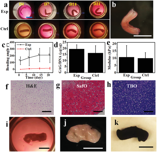
As indicated earlier (Figure 2c,d), the shape of the bioconstruct can be tuned by adjusting the UV time for either the bottom layer or the upper layer. We demonstrated that increasing the UV time for the upper layer can also prolong the retention duration of the cell condensate layer before being released (Figure 5 and Figure S15, Supporting Information). To keep the same MG degradation profile and increase the deformability of the bilayer structure, we reduced the UV irradiation time from 50 to 30 s to fabricate the bottom layer while maintaining a 20 s UV irradiation time for the upper layer, offering cell-strip laden bilayers (30 s/20 s UV crosslinking time) with greater curling, and yielding helix-shaped cartilage-like tissues after culturing for 21 days in chondrogenic media (Figure 6i and Figure S23, Supporting Information). Unlike the “C”-shaped cartilage-like tissues, the helix cartilage-like tissues were wrapped tightly with the gradient hydrogel (Movie S4, Supporting Information) and did not separate spontaneously despite complete MG degradation. Since the formed cartilage-like tissues were very robust, they could be separated manually while maintaining their helix structures (Figure 6j and Movie S5, Supporting Information). The whole construct also strongly stained with TBO due to the presence of a large amount of GAG (Figure 6k). The tunability illustrated herein highlights the versatility of this system to engineer cell condensation-based tissues with defined configurations on demand. Our results sufficiently demonstrate that this 4D cell-condensate bioprinting strategy possesses high potential in the field of tissue engineering and may be expanded to other regenerative medicine related areas.
The 4D bioprinting technique opens a new avenue to engineer bioconstructs through a user-defined shape-morphing process, enabling dynamic 4D biofabrication at physiologically relevant timescales. Currently, in the 4D bioprinting field, research is still focused on the development of intelligent materials that undergo geometrical transformations under physiological conditions.[46] Several reports to date have shown the feasibility of using cytocompatible polymers as bioinks to print high-resolution hydrogel constructs.[31-35, 47] In these studies, cells were either seeded on the hydrogel surface or encapsulated inside the formed hydrogels. However, the seeding of cells on the hydrogel surface fails to replicate the 3D cellular microenvironment, while encapsulation of cells inside the hydrogels interferes with critical cell-to-cell interactions. Here we have proposed a novel 4D bioprinting strategy to address the challenges in the formation of geometrically complex scaffold-free 3D cell condensate constructs with defined configurations capable of undergoing temporally controllable and predefined architectural changes. Through a rational bilayer design using a gradient hydrogel as an actuation layer and a photocurable and biodegradable MG layer as a temporally controlled cell condensate-supporting layer, stable cell condensates with diverse and tunable conformational changes over time were obtained through programmable deformations. The cell condensate-derived tissues or other bioconstructs can be liberated after being cultured to a predetermined time point. As a proof-of-concept study, we demonstrated the fabrication of letter “C”-shaped and helix-shaped cartilage-like tissues. The unique features of this system on the whole lie in the (i) adjustable shape morphability, (ii) smooth and high-resolution MG printing and high-fidelity cell-only printability within the pre-printed MG layer, (iii) cytocompatible materials and processing, including 4D printing and shape transformations, and importantly (iv) controllable cell condensate formation, maturation, and release. This is the first time, to the authors’ best knowledge, that a 4D system has been implemented to achieve deformable cell condensations. We also observed very limited shape change caused by cell-contractile forces in the ex vivo 4D tissue engineering study. Given that cell-contractile forces can occur strongly within cell condensates and, as observed in this study, can be a natural trigger for impelling the 4D process, it might be of value to design a 4D cell-condensate bioprinting system that involves the cell-contractile force as a collaborative, primary or even the sole stimulus.
3 Conclusions
In this work, we have constructed a unique 4D bioprinting system to produce specifically shaped cell condensates for applications such as developmental mimicry and tissue engineering. The establishment of this strategy may shed valuable insights into the future development of 4D bioprinting associated with scaffold-free tissue regeneration. This system addresses the issues associated with the use of scaffold-based 4D tissue engineering approaches. Our strategy is effective in enabling construction of scaffold-free cell condensates with diverse geometries that can be designed to undergo preprogrammed shape changes over time, offering a versatile platform for customized biofabrication.
4 Experimental Section
For chemicals and instruments, materials synthesis, swelling and degradation tests, Young's modulus measurement, rheological testing, interfacial adhesion testing, cell expansion, and live/dead staining, please refer to the Supporting Information.
MG Preparation
MGs were prepared using a modified procedure from the reported literature.[43] To make the stock MGs, O5M20A (1.2 g) was dissolved in deionized water (diH2O, 60 mL) and then was slowly dispensed into a gelling bath containing an aqueous solution of CaCl2 (600 mL, 0.2 m) under fast stirring with a magnetic stir bar. After fully ionically crosslinking overnight, the resultant hydrogel beads were collected, washed once with 40 mL of 70% ethanol (EtOH)/water (H2O), and then blended twice using a household blender (Osterizer MFG, at “pulse” speed) for 2 min with 120 mL of 70% EtOH/H2O. Then, the MGs were obtained and loaded into 50 mL conical tubes and centrifuged at 4200 rpm for 5 min and stored at 4 °C for future use.
To recover the MGs for use, the as-prepared MGs (5 mL) in 70% EtOH/H2O were washed 3 times by replacing the previous media with 25 mL of 0.05% (w/w) PI-contained diH2O and then vortexed (Fisher STD Vortex Mixer, Fisher Scientific, 10× speed) for 2 min every time and subsequently washed 1 time by replacing the previous media with 25 mL of 0.05% (w/w) PI-containing DMEM-LG and vortexed (10× speed) for 10 s. This recovered MGs were used for further experiments.
Gradient and Non-Gradient Hydrogel Preparation
Gradient hydrogels were used as the actuation layer to drive shape morphing. The preparation was according to a similar procedure described in the reported literature.[35] Briefly, a mixed solution of polymer [OMA 6% w/w, OMA (6% w/w)/GelMA (6% w/w)], PI (0.05% w/w), and UV absorber [RhB (0.01% w/v)/HMAP (0.02%)] in DMEM-LG was placed between two quartz plates with 0.6 mm spacers and subsequently photocrosslinked with UV light (EXFO OmnicureR S1000, Lumen Dynamics Group) at 12 mW cm−2 for a certain time (20–40 s) to form a O5M45A hydrogel disc with a gradient in crosslinking density throughout the thickness, which was denoted as O5M45A(g) or O5M45A/GelMA(g). Non-gradient hydrogels were used for comparison and were fabricated similarly without using a UV absorber and were denoted as O5M45A or O5M45A/GelMA. The gradient/non-gradient hydrogels discs were cut into hydrogel sheets with dimensions of 25 × 25 mm as a substrate for the MG printing.
MG Printing
The MG printing was performed using a 3D printer (PrintrBot Simple Metal 3D Printer, Printrbot) modified with a syringe-based extruder. More information about this printer can be found in the literature.[43] The STL files for the bioink printing were generated from www.tinkercad.com.
The MGs were loaded into a 1 mL glass syringe (Hamilton, Reno, NV), which was connected to a 22-gauge stainless-steel needle (McMaster-Carr) and mounted into the syringe pump extruder on the 3D printer. The above O5M45A(g) hydrogel sheet was flipped and placed on a quartz plate with low-crosslinking side attaching the quartz plate surface. The tip of the needle was positioned at the center and near the surface of the O5M45A or O5M45A(g) hydrogel sheet, and the print instructions were sent to the printer using the host software (Cura Software, Ultimaker), which is an open-source 3D printer host software. The MGs were printed under 4 mm s−1 printing speed with 100% infilling density. After printing, the obtained constructs were used for further cell-only printing or immediately photocured under UV irradiation. Then, the cell-free constructs were cut into specific shapes (e.g., strip, sheet, and disc). These hydrogels were then carefully transferred into a tissue culture plate for culturing to monitor the shape change or/and allow cell differentiation. The hydrogels were imaged, and the bending angles were quantified according to the previous literature.[45]
Bilayer Hydrogel Fabrication
Gradient/non-gradient hydrogels as substrates were fabricated as above and MGs were printed on the surface of the hydrogel substrates as above. The bilayer hydrogels were then photocrosslinked for a certain time. To distinguish the UV time for the bilayer fabrication, the total UV time was denoted as gradient layer time/MG layer time. For example, if the UV time for the gradient hydrogel layer and the MG layer is set to 30 and 20 s, respectively, the overall UV time for the bilayer fabrication is denoted as 30 s/20 s. The bilayer is denoted as bottom hydrogel_upper hydrogel. For example, O5M45A/GelMA(g)_O5M20A MG is a bilayer consisting of O5M45A/GelMA(g) (bottom layer) and O5M20A MG (upper layer).
Cell-Only Bioprinting
HeLa and hMSC cells as bioinks were loaded into 3 mL of Luer lock syringes (Becton, Dickinson and Company, NJ), connected to a 25G stainless steel needles (McMaster-Carr) and mounted into the BIO X 3D printer (CELLINK, MA). Pre-printed MGs described above (MG printing) were used as the supporting batch for 3D cell-only printing. The printing parameters were set to 95% infilling density, 2 mm s−1 printing speed, and 0.8 µL s−1 (HeLa cells) or 1.0 µL s−1 (hMSCs) extrusion rate. For printing strips, sheets, discs, bars, and grids, the layer thickness was set to 0.2 mm, and one layer of cells was printed (Movie S3, Supporting Information). For printing the cell cuboid (Figure S12, Supporting Information), the layer thickness was set to 0.25 mm, and 16 layers of cells were printed. After 3D printing of the cell-only bioinks, cell-laden O5M20A MGs were stabilized by photocrosslinking under UV for a specified time. The photocrosslinked cell-laden bioconstructs were transferred into a 4-well tissue culture plate for culturing the strip-shaped hydrogels with 4 mL of GM or a 6-well tissue culture plate for culturing bioconstructs with other shapes with 10 mL of GM to record shape change and assess cell viability through a live/dead staining assay. The media was changed every day.
Ex Vivo Cartilage-Like Tissue Engineering, Biochemical Quantification, Histology, and Immunohistochemistry
The hMSCs at passage 4 (P4) were used for the chondrogenesis study. The cells were harvested for cell-only bioprinting when they reached ≈80% confluence. The cell-laden bilayer hydrogel strips were cultured in chondrogenic media. The UV application time for the letter “C”- and helix-shaped bioconstruct formation was set to 50 s/20 s and 30 s/20 s, respectively. For cartilage-like tissue formation, the hMSC-laden hydrogels were cultured in 4 mL of chondrogenic media in a humidified incubator at 37 °C with 5% CO2 over a course of 21 days, and 2 mL of media was changed every day. The cartilage-like tissues were obtained at day 21 and cut into small pieces for biochemical analysis, Young's modulus testing, and histological staining.
For biochemical analysis, the small tissue pieces were digested in 0.5 mL of papain solution (Sigma) at 65 °C for 24 h and centrifuged for 10 min at 15 000 rpm, and then the supernatants were collected for DNA and glycosaminoglycan (GAG) quantifications (N = 3).
Per the manufacturer's instructions, a Picogreen assay kit (Invitrogen) was used to quantify the DNA content in the supernatant. Fluorescence intensity of the dye-conjugated DNA solution was measured using a microplate reader with an excitation of 480 nm and emission of 520 nm.
The GAG content was quantified using a DMMB (1,9-dimethylmethylene blue) assay.[43] 40 µL of supernatant from the digested samples was transferred into 96-well plate, to which 125 µL of DMMB solution was then added. Absorbance at 595 nm was recorded on a microplate reader. GAG content was normalized to DNA content.
The small cartilage-like tissues were fixed with 10% neutral buffered formalin (NBF) overnight at 4 °C, dehydrated, and embedded in paraffin. Briefly, tissue samples were cut into 5 µm thick sections using a Leica RM2255 rotary microtome (Leica Microsystem Ltd., Milton Keynes, UK). Slide sections were then deparaffinized and stained with H&E stains to observe gross cell and tissue morphology,[40] and SafO with a Fast Green counterstain[48] and TBO for GAG indication.[49] To evaluate the production of type II collagen and N-cadherin, immunohistochemistry was performed using a rabbit polyclonal anti-human type II collagen primary antibody or a mouse polyclonal anti-human N-cadherin primary antibody, respectively, followed by rinsing with PBST three times and further incubation with a secondary horseradish peroxidase (HRP)-antibody. Visualization was performed by staining the slides with an AEC substrate kit for type II collagen or a DAB kit for N-cadherin. Stained samples were visualized by brightfield microscope (Nikon Eclipse TE300, Japan) under bright field.
TBO staining was also used to stain the entire helix-shaped cartilage-like tissue. The whole tissue was collected and stained with TBO for 30 min and washed with PBS 3 times to remove the unbound stain.[43]
Data Presentation and Statistical Analysis
All quantitative data were expressed as mean ± SD. Three samples (N = 3) unless specified were used for statistical analysis. Statistical analysis was performed with one-way analysis of variance (ANOVA) with Tukey honestly significant difference post hoc tests using Origin software (OriginLab Corporation, Northampton, MA). A value of p < 0.05 was considered statistically significant.
Acknowledgements
The authors gratefully acknowledge funding from the National Institutes of Health's National Institute of Arthritis and Musculoskeletal and Skin Diseases (R01AR074948) and National Institute of Biomedical Imaging and Bioengineering (R01EB023907). The contents of this publication are solely the responsibility of the authors and do not necessarily represent the official views of the National Institutes of Health.
Conflict of Interest
The authors declare no conflict of interest.
Open Research
Data Availability Statement
The data that support the findings of this study are available from the corresponding author upon reasonable request.


