
Modeling of additive manufacturing processes with time-dependent material properties using physics-informed neural networks
Abstract
Recently, physics-informed neural networks (PINNs) have been effectively utilized in a wide range of problems within the domains of applied mathematics and engineering. In PINNs, the governing physical equations are directly incorporated into the loss function of the network and a conventional labeled dataset is not required for its training. In order to successfully simulate the additive manufacturing processes with concrete, a novel process-based FE-simulation has been developed where the Drucker–Prager plasticity model is used as the material model. In this work, we will examine the deployment of a PINN to substitute the Newton–Raphson iterations that occur in the return-mapping algorithm of the Drucker–Prager plasticity model.
1 INTRODUCTION
The feasibility of additive manufacturing, also known as 3D printing, has been successfully showcased in the construction industry, owing to its ability to eliminate the need for large formworks typically used in traditional casting processes [1, 2]. With 3D printing, components can be directly constructed layer by layer, eliminating the need for preexisting molds or subsequent subtraction or forming processes. However, the time-dependent material properties of concrete pose limitations that must be addressed to fully leverage the potential of 3D printing in construction. Concrete exhibits a significantly longer curing time compared to plastics, and although curing accelerators can shorten this time, the material's rheology remains measurable for several minutes [3]. Consequently, the buildability of components is constrained, as elastic and plastic deformation can lead to structural collapse when printed layers are unable to support their own weight and the weight of subsequent layers [4].
 (1)
(1) (2)
(2)| Density ρ [kg/mm3] |  |
|---|---|
Young's modulus  [MPa], t [min] [MPa], t [min] |
 |
Cohesion  [MPa], t [min] [MPa], t [min] |
 |
| Poisson's ratio v |  |
| Friction angle φ |  |
| Dilatancy angle ψ |  |
2 PROCESS-BASED FINITE ELEMENT SIMULATION
In order to examine how the process parameters affect the geometry of the printed component, a finite element simulation based on the printing process was developed [5]. This simulation allowed for the direct construction of the printed geometry by utilizing the printing trajectory and process parameters. The cross-sectional shape of each printed layer can be approximated as a rectangle, with its width and height dependent on both the nozzle velocity and the distance to the printing surface, as illustrated in Figure 1.

The description of the printed component's geometry is represented by its mesh. To convert the quasi 2D nodes of each cross section from the local coordinate system (depicted in green), a coordinate transformation is required. This transformation is performed by a rotational matrix Q and determines the mapping of the nodes into the global coordinate system (shown in black).
The global 3D connectivity matrix is formed by combining two successive quasi 2D meshes, resulting in eight nodes per 3D element. To determine the time stamp of each element, a sequential loop is employed. The time stamp of the next element  is computed by considering the previous timestamp
  , and the speed of the nozzle
  . To conveniently incorporate additional layers, the z-coordinate of all nodes from the preceding layer can be adjusted by the designated layer height
  . The complete geometry construction and implementation of this process-based FE-simulation has been provided in previous work [5].
 , as well as the internal forces
  arising from pre-existing internal stresses, are computed for each time step. Then the standard system of equations (equilibrium equation) is solved,
 (3)
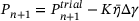
(3) is the displacement increment. Once the actual displacements have been computed, the return-mapping algorithm is employed to ascertain the resulting stresses. In the first step of this algorithm, the computed displacement increment
  is utilized to determine the corresponding incremental total strain
  . Initially, the assumption is made that this strain is purely elastic, and the corresponding stress prediction can be calculated using the elastic law,
 (4)
(4) is the elasticity matrix ,
  and
and  refer the elastic and plastic strain, respectively. When the predicted stress falls within the cone (Figure 2B), the true stress corresponds to the predicted stress, and the state variables can be updated accordingly. However, if the predicted stress lies outside the surface of the cone, plastic yielding has taken place, and the predicted stress needs to be mapped onto the yield surface. In the case of the associative Drucker–Prager model, the yield flow, indicating the direction of plastic strain, is perpendicular to the yield surface. However, in the nonassociative case, the direction of yield flow is not strictly perpendicular to the yield surface.
3 RETURN MAPPING ALGORITHM
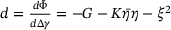
 (5)
(5) is the hydrostatic pressure and c is the cohesion. The selection of the constants ξ and η is determined based on the desired approximation (outer-edges, inner-edges, associative, nonassociative). The cohesion value
  depends on the accumulated plastic strain
  due to strain-softening and on the elapsed time t due to the time-hardening nature of fresh concrete. For perfectly plastic materials, c is independent of the accumulated plastic strain
  and, for linear hardening models, the hardening function reads
 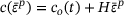 , where H denotes the hardening modulus. In such cases, the return mapping equations shown in the algorithm [11] will be linear and
  can be directly computed in closed form. In the current study, a nonlinear strain softening model with exponential strain decay will be investigated, where the cohesion
 (6)
(6) . The coefficient
  and the following experimentally determined material properties were used in the study (Algorithm 1).
Algorithm 1. Return mapping algorithm.
Set initial guess for  and calculate yield function value and calculate yield function value  |
 , ,  |
 |
while  do do |
 (Hardening slope) (Hardening slope) |
 (Residual derivative) (Residual derivative) |
 (New guess for (New guess for  ) ) |
 |
 |
| end while |
| Update variables |
 |
 |
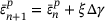
 cannot be directly computed and must be calculated iteratively using the Newton–Raphson method. An initial guess for the plastic multiplier
  is made and the accumulated plastic strain in the current step is assumed to equal the accumulated plastic strain from the previous step
  . The accumulated plastic strain
  and elapsed time t is used to calculated the current value of cohesion
  , which will subsequently determine the yield function value
  . If the value
  exceeds a specified tolerance
  , the predicted stress state lies ouside the Drucker–Prager cone and return mapping needs to be performed. This is done iteratively using the following steps, where, first, the hardening slope
 (7)
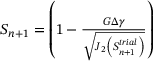
(7) . Next, the residual derivative is computed and used to update the guess value for
  . To calculate the residual derivative, the shear modulus G and bulk modulus K are required, which are values derived from the material properties. Finally, the
  is recalculated to determine the new yield function value
  and the procedure is repeated till the value of
  is less than the specified tolerance
  .
.4 IMPLEMENTATION OF THE PHYSICS INFORMED NEURAL NETWORK PINN
A PINN will be implemented in order to eliminate the iterative process and instead directly determine the plastic multiplier  .
.
Figure 3A illustrates the working principle of a single neuron and is a graphical representation of a simple mathematical operation. Here, the three inputs to the neuron  are multiplied, respectively, by weights
  and a so called bias b is added to the summation. The output of the summation is passed as input into a nonlinear activation function (tanh function), and the resulting value is the output
 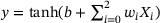 of that specific neuron.

A feed forward neural network is composed of many such neurons and has the capability to approximate any given function, given that an adequate number of layers and neurons are employed as proved by the universal approximation theorem [12]. In order to accurately approximate the function, the weights and biases of the network must be adjusted during the training process. The key distinction between a standard neural network and a PINN resides in the training procedure and the training dataset. In the supervised training process of a standard neural network, labels are required, which are then compared to the predicted output. The mean square error (MSE) between the two is calculated, and the neural network parameters θ (weights and biases) are adjusted during training to minimize this error. In contrast to the training of standard neural networks, PINNs do not require labels. Instead, the PINN is trained utilizing the underlying physical equation at the collation points. These collation points represent the points where the input dataset for the neural network is generated. Figure 4 illustrates the operational concept of the implemented PINN.

Initially, an input dataset needs to be generated. To achieve this, a simulation of a curved wall section was performed (Figure 2A) using the implemented finite element simulation. During this simulation, values for  generated by the material model were recorded and saved. In the next step, the minimum and maximum values (recorded range) for each of the four parameters were identified. Using the Latin hypercube method, 100 000 combinations of these four parameters were generated within the recorded range. These combinations of parameters are referred to as the collocation points and the PINN will be trained at these points. It should be noted that a single simulation was sufficient to provide all the required data needed to train the PINN, which is a significant advantage over traditional neural networks.
 of the network is predicted for a given input combination. This value of
  is used to calculate the corresponding plastic strain increment
  and value of cohesion c. These values, together with the input combination
  and predicted plastic multiplier
  , are plugged into the consistency equation
 (8)
(8)5 PERFORMANCE OF THE PHYSICS INFORMED NEURAL NETWORK PINN
In Figure 5A, it can be observed that the loss function of the neural network quickly converges. After training of the PINN, the combinations of  saved during the simulation were tested on the PINN and the predicted value of the plastic multiplier
  (shown in red) was compared with the iteratively calculated values (shown in blue).

 values obtained iteratively versus with PINN.
 . The results show an excellent match between the two approaches (numerical
  vs. PINN
  ) and has an average percentage difference
  of 5.63%
 (9)
(9) to converge. Then the cost for the numerical iterations can be compared with the cost of the neural network, to determine which material models are suited to be replaced with PINNs.
6 CONCLUSION AND OUTLOOK
In this work, the Drucker–Prager plasticity model with exponential srain-softening was used as a material model for fresh concrete in AM build-up simulations. In addition to the strain softening caused by the accumulated plastic strain  , the material values were time-dependant. In FE-simulations, the governing equations of such material models are iteratively solved using the Newton–Raphson method within the return-mapping algorithm. In this work, it was successfully demonstrated that a PINN could be used to substitute the numerical iterations that take place, thereby directly determining the plastic multiplier (
 ). The average percentage difference between the numerically determined value and through the PINN determined value was 5.13%. In future work, this method can be extended to include the apex-treatment of the return mapping algorithm, where a further iteration process takes place. Additionally, hyperbolic
  and power law
  strain-softening models can be analyzed and solved with PINNs. The choice of the optimal material model depends on the particular concrete type and admixture being used, and it can be determined by fitting the model parameters to experimental data.
ACKNOWLEDGMENTS
The authors gratefully acknowledge the funding by the Deutsche Forschungsgemeinschaft (DFG—German Research Foundation)—Project no. 414265976. The authors would like to thank the DFG for the support within the SFB/Transregio 277—Additive manufacturing in construction (Subproject B04).
Open access funding enabled and organized by Projekt DEAL.