Volume 23, Issue 4 e202300180
RESEARCH ARTICLE
Open Access

Time-optimal trajectory planning of a redundantly actuated planar parallel robot driven with series elastic actuators

Thomas Kordik

Corresponding Author

Thomas Kordik

Institute of Robotics, Johannes Kepler University Linz, Linz, Austria

Correspondence

Thomas Kordik, Institute of Robotics, Johannes Kepler University Linz, Altenberger Str. 69, 4040 Linz, Austria.

Email: [email protected]

Search for more papers by this author
Christian Zauner

Christian Zauner

Institute of Robotics, Johannes Kepler University Linz, Linz, Austria

Search for more papers by this author
Tobias Marauli

Tobias Marauli

Institute of Robotics, Johannes Kepler University Linz, Linz, Austria

Search for more papers by this author
Hubert Gattringer

Hubert Gattringer

Institute of Robotics, Johannes Kepler University Linz, Linz, Austria

Search for more papers by this author
Andreas Müller

Andreas Müller

Institute of Robotics, Johannes Kepler University Linz, Linz, Austria

Search for more papers by this author
First published: 31 October 2023

Abstract

This paper addresses the time-optimal trajectory planning of a redundantly actuated parallel robot driven by series elastic actuators. Here, the actuation redundancy allows prestressing the elastic components of the drives and enables more degrees of freedom in the trajectory planning. To this end, a time-optimal control problem is formulated that takes also the physical constraints into account, that is actuation torques, task and joint space limits and self-collisions. A flatness-based parametrization of the dynamics is used in the nonlinear optimization problem and solved with the multiple shooting technique within the CasADi framework using IPOPT as a solver. Results are shown and compared to time-optimal trajectories, both redundantly and non-redundantly actuated with rigid drives.

1 INTRODUCTION

Current research on parallel kinematic mechanisms (PKM) addresses the use of elastic components aiming at applications where well-defined physical compliance is important, for example human-robot interaction and rehabilitation. Redundant actuation of PKM is another research direction that was proposed to increase their dynamic capabilities and performance. In this paper, the topics of redundant actuation and series elastic actuators (SEA) for a planar parallel robot are combined and exploited for time-optimal trajectory planning. Time-optimal motion planning for redundantly actuated robots driven by rigid drives has been addressed in [1, 2], whereas research about motion planning of parallel robots equipped with SEA is directed towards energy-optimality ([3]). The resulting dynamic model of a SEA-actuated PKM splits into two dynamical systems coupled by the elastic component of the SEA only. The redundant actuation of the compliant PKM further results in an additional degree of freedom, which allows preloading the elastic components. This enables to store and release potential energy at the starting and terminal points. This control system is also differently flat ([4, 5]). This contribution focuses on the time-optimal motion planning of redundantly actuated SEA-driven PKM taking into account physical constraints and system dynamics. Time-optimal control problems (TOCP) for the offline point-to-point trajectory planning are formulated for a non-redundantly and a redundantly actuated planar PKM prototype, each equipped with SEA and standard rigid drives, in order to compare to conventionally actuated PKM. This results in considering four different PKM setups. In Section 2, necessary model properties are highlighted and in Section 3, the nonlinear optimal control problems are derived. Section 4 shows and compares solutions for a numerical example and in Section 5 future work ideas are proposed.

2 MODELING

To take into account the dynamic limits for the time-optimal trajectory planning, the dynamics of the systems need to be determined. Various approaches for the dynamic modeling of PKM equipped with rigid actuators are established in [6-9]. For PKM equipped with SEA the derivation of the equations of motions (EOM) can be found in [10]. In the following Sections 2.1 and 2.2 only the final motion equations are provided to highlight the systems' properties addressed in Section 3. In both cases the minimal coordinate formulation is used. For a detailed modeling we refer to the quoted literature.

2.1 Dynamic model of PKM driven with rigid actuators
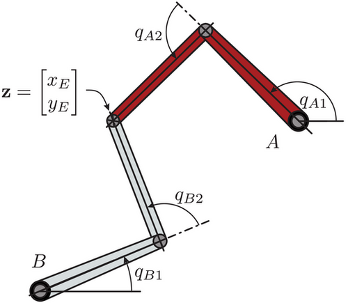
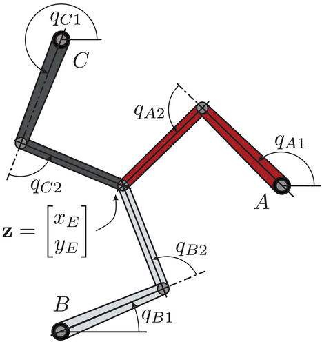
Figures 1 and 2 show the setups of a planar PKM. Two identical arms, enumerated by i = A , B $ i=A,B$ , are assumed for the non-redundantly actuated PKM and three with i = A , B , C $i = A,B,C$ for the redundantly-actuated case, respectively. All arms consist of an actuated link, where the drives are stationary base-mounted and a passive link. For both compositions the EOM can be described by
M ( q ) s ̈ + g ( q , s ̇ ) = B ( q ) u , $$\begin{equation} \mathbf {M}(\mathbf {q}) \ddot{\mathbf {s}} + \mathbf {g}(\mathbf {q},\dot{\mathbf {s}})= \mathbf {B}(\mathbf {q})\mathbf {u}, \end{equation}$$ (1)
with the mass matrix M ( q ) $\mathbf {M}(\mathbf {q})$ and the vector of joint angles q = [ q i 1 , q i 2 ] T = [ q 1 T , q 2 T ] T $\mathbf {q} = [q_{i1},q_{i2}]^T = [\mathbf {q}_{1}^T,\mathbf {q}_{2}^T]^T$ where q 1 $\mathbf {q}_1$ is the vector of actuated link angles q i 1 $q_{i1}$ and q 2 $\mathbf {q}_2$ the vector of passive link angles q i 2 $q_{i2}$ where i = A , B $i = A,B$ holds for the non-redundantly actuated setup, see Figure 1, and i = A , B , C $i = A,B,C$ in case of actuation redundancy, depicted in Figure 2, respectively. The minimal velocities are denoted with s ̇ $\dot{\mathbf {s}}$ and the minimal accelerations with s ̈ $\ddot{\mathbf {s}}$ . The input torques are given by u $\mathbf {u}$ and mapped onto the minimal coordinates by the matrix B ( q ) $\mathbf {B}(\mathbf {q})$ . All remaining forces and torques are summarized in g ( q , s ̇ ) $\mathbf {g}(\mathbf {q},\dot{\mathbf {s}})$ . For both cases the end-effector (EE) coordinates s ̇ = z ̇ = [ x ̇ E , y ̇ E ] T R 2 $\dot{\mathbf {s}} = \dot{\mathbf {z}}= [\dot{x}_E, \dot{y}_E]^T \in \mathbb {R}^2$ , the coordinates of the center point where all arms are connected, are chosen as minimal coordinates. In the case of actuation redundancy, see Figure 2, this leads to B ( q ) R 2 × 3 $\mathbf {B}(\mathbf {q}) \in \mathbb {R}^{2 \times 3}$ , otherwise it results in B ( q ) R 2 × 2 $\mathbf {B}(\mathbf {q}) \in \mathbb {R}^{2 \times 2}$ . The kinematic relation between the time derivatives of all joint coordinates and minimal velocities is given by q ̇ = H ( q ) s ̇ = H ( q ) z ̇ $\dot{\mathbf {q}} = \mathbf {H}(\mathbf {q})\dot{\mathbf {s}} = \mathbf {H}(\mathbf {q})\dot{\mathbf {z}}$ .
Details are in the caption following the image
Non-redundantly actuated PKM with rigid drives. PKM, parallel kinematic mechanisms.
Details are in the caption following the image
Redundantly actuated PKM with rigid drives. PKM, parallel kinematic mechanisms.

2.2 Dynamic model of PKM driven with SEA
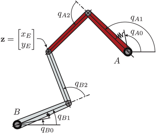
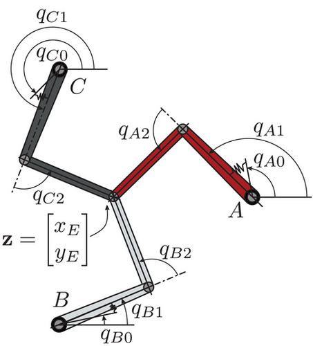
Analogously to the previous section, the planar PKM setups depicted in Figures 3 and 4, contain again identical arms consisting of an actuated and a passive link each. Here, the actuators are implemented as stationary, base-mounted SEA which are modeled as drives with a simple rotation spring between the motor and the output-side. Subsequently, there is no direct feed-through from the actuation to the EE coordinates as both systems are only coupled by the springs. The dynamic motion equations are governed by
M M 0 0 M z ( q ) q ̈ 0 z ̈ + 0 g z ( q , z ̇ ) + K K H a T ( q ) K H a T ( q ) K q 0 q 1 = u 0 . $$\begin{equation} \def\eqcellsep{&}\begin{bmatrix} \mathbf {M}_\mathrm{M} & 0 \\ 0 & {\mathbf {M}}_\mathrm{z}(\mathbf {q}) \end{bmatrix} \def\eqcellsep{&}\begin{bmatrix} \ddot{\mathbf {q}}_0 \\ \ddot{\mathbf {z}} \end{bmatrix} + \def\eqcellsep{&}\begin{bmatrix} \mathbf {0} \\ {\mathbf {g}}_\mathrm{z}(\mathbf {q},\dot{\mathbf {z}}) \end{bmatrix}+\def\eqcellsep{&}\begin{bmatrix} \mathbf {K} & -\mathbf {K}\\ -\mathbf {H}_\mathrm{a}^T(\mathbf {q})\mathbf {K} &\mathbf {H}_\mathrm{a}^T(\mathbf {q})\mathbf {K} \end{bmatrix} \def\eqcellsep{&}\begin{bmatrix} \mathbf {q}_0 \\ \mathbf {q}_1 \end{bmatrix} = \def\eqcellsep{&}\begin{bmatrix} \mathbf {u} \\ \mathbf {0} \end{bmatrix}. \end{equation}$$ (2)
The vector of all joint angles is denoted with q ¯ = [ q i 0 , q i 1 , q i 2 ] T = [ q 0 T , q T ] T $\bar{\mathbf {q}} = [q_{i0},q_{i1},q_{i2}]^T = [\mathbf {q}_0^T, \mathbf {q}^T]^T$ and the vector of motor angles q i 0 $q_{i0}$ with q 0 $\mathbf {q}_0$ where i = A , B $i = A,B$ or i = A , B , C $i = A,B,C$ holds depending on the setup, depicted in Figures 3 and 4, respectively. One can immediately see the kinematic decoupling of (2), with the upper part representing the EOM of the actuators described by the vector of motor angles q 0 $\mathbf {q}_0$ and the bottom part representing the EOM of the PKM described by the EE coordinates z = [ x E , y E ] T $\mathbf {z} = [x_E, y_E]^T$ . The moments of inertia of all motors are summarized in M M $\mathbf {M}_\mathrm{M}$ , u $\mathbf {u}$ is the vector of motor torques and the spring stiffnesses of all SEA are collected in K $\mathbf {K}$ . The mass matrix of the PKM itself is denoted with M z ( q ) $\mathbf {M}_\mathrm{z}({\mathbf {q}})$ and all remaining forces are expressed as g z ( q , z ̇ ) R 2 $\mathbf {g}_\mathrm{z}({\mathbf {q}},\dot{\mathbf {z}}) \in \mathbb {R}^2$ . For both cases, the minimal velocities s ̇ = [ q ̇ 0 , z ̇ ] T $\dot{\mathbf {s}} = [\dot{\mathbf {q}}_0, \dot{\mathbf {z}}]^T$ consist of the motor and the EE coordinates. The kinematic relation between the time derivatives of all joint angles q ¯ ̇ $\dot{\bar{\mathbf {q}}}$ and the minimal velocities s ̇ $\dot{\mathbf {s}}$ is defined as q ¯ ̇ = H ( q ) s ̇ $\dot{\bar{\mathbf {q}}} = \mathbf {H}({\mathbf {q}})\dot{\mathbf {s}}$ . Emphasis lies here on the matrix H a ( q ) $\mathbf {H}_\mathrm{a}({\mathbf {q}})$ , a submatrix of H ( q ) $\mathbf {H}(\mathbf {q})$ representing the relation between the actuated link velocities and the EE velocities q ̇ 1 = H a ( q ) z ̇ $\dot{\mathbf {q}}_1 = \mathbf {H}_\mathrm{a}({\mathbf {q}})\dot{\mathbf {z}}$ and more precisely in (2), how the spring torques are mapped onto the EE coordinates. Its structure can be described by
q ̇ 1 = H a 1 H a 2 H a 3 H a 4 H a ( q ) z ̇ and q ̇ 1 = H a 1 H a 2 H a 3 H a 4 H a 5 H a 6 H a ( q ) z ̇ , $$\begin{equation} \dot{\mathbf {q}}_1 = \underbrace{{\left[ \def\eqcellsep{&}\begin{array}{cc}H_{\mathrm{a}1}&H_{\mathrm{a}2}\\[3pt] H_{\mathrm{a}3}&H_{\mathrm{a}4} \end{array} \right]}}_{\mathbf {H}_\mathrm{a}({\mathbf {q}})} \dot{\mathbf {z}}\qquad \text{and} \qquad \dot{\mathbf {q}}_1 = \underbrace{{\left[ \def\eqcellsep{&}\begin{array}{cc}H_{\mathrm{a}1}&H_{\mathrm{a}2}\\[3pt] H_{\mathrm{a}3}&H_{\mathrm{a}4}\\[3pt] H_{\mathrm{a}5}&H_{\mathrm{a}6} \end{array} \right]}}_{\mathbf {H}_\mathrm{a}({\mathbf {q}})} \dot{\mathbf {z}}, \end{equation}$$ (3)
where the matrix H a ( q ¯ ) $\mathbf {H}_\mathrm{a}(\bar{\mathbf {q}})$ is quadratic and nonsingular for the non-redundantly actuated setup, whereas in case for redundant actuation, it is no longer invertible.
Details are in the caption following the image
Non-redundantly actuated PKM driven with SEA. PKM, parallel kinematic mechanisms; SEA, series elastic actuators.
Details are in the caption following the image
Redundantly actuated PKM driven with SEA. PKM, parallel kinematic mechanisms; SEA, series elastic actuators.

3 TIME-OPTIMAL POINT-TO-POINT TRAJECTORY PLANNING

The time-optimal control problem is formulated to plan a trajectory between a starting and terminal point in minimum time, while taking into account the robots dynamic limits and avoid self-collision as well as task and joint space violations. The common approach is to define the objective as the weighted sum of the terminal time T and a regularization term for better convergence. All four considered robot setups in Section 2 are differentially flat ([5]). Therefore, using a coordinate transformation, the system dynamics can be included in the TOCP by an integrator chain described by ODE x ̇ = f ( x , v ) $\dot{\mathbf {x}} = \mathbf {f} (\mathbf {x},\mathbf {v})$ with the integrator state vector x $\mathbf {x}$ and input v $\mathbf {v}$ . Each TOCP described in Sections 3.1-3.3 is solved using the multiple shooting method [11] within the CasADi framework [12]. As a solver, IPOPT [13] was applied. Numerical integration is done with the explicit Runge-Kutta method of fourth order, assuming piecewise-constant integrator inputs v $\mathbf {v}$ .

3.1 PKM driven with rigid actuators

Both, the redundantly-actuated as well as non-redundantly actuated parallel robots described in Section 2.1 exhibit a vector relative degree r = { 2 , 2 } $\mathbf {r} = \lbrace 2,2\rbrace$ ([4]) if the EE position z $\mathbf {z}$ is chosen as flat output y $\mathbf {y}$ . Therefore, it would be sufficient to require an EE-path that is twice differentiable w. r. t. time. However, it is beneficial for robot applications to also limit the jerk. Consequently, the EE-jerk is used as control input and the state vector is given by . The TOCP can be stated as a nonlinear optimization problem by
min q , z , z ̇ , z ̈ , v , u , T 0 T w t + w u u T u d t $$\begin{align} &\hspace*{-138pt}\min _{\mathbf {q},\mathbf {z},\dot{\mathbf {z}},\ddot{\mathbf {z}},\mathbf {v},\mathbf {u},T} \int _{0}^{T} {\left(w_t + w_u \mathbf {u}^T \mathbf {u} \right)} \mathrm{d}t\quad \end{align}$$ (4)
s . t . x ̇ = d d t z z ̇ z ̈ = z ̇ z ̈ v $$\begin{align} &\hspace*{-147pt}\mathrm{s.t.}\quad \dot{\mathbf {x}} = \dfrac{\mathrm{d}}{\mathrm{d}t} {\left( \def\eqcellsep{&}\begin{array}{c}\mathbf {z}\\[3pt] \dot{\mathbf {z}} \\[3pt] \ddot{\mathbf {z}} \end{array} \right)} = {\left( \def\eqcellsep{&}\begin{array}{c}\dot{\mathbf {z}} \\[3pt] \ddot{\mathbf {z}} \\[3pt] \mathbf {v} \end{array} \right)}\qquad\qquad\qquad \end{align}$$ (5)
M ( q ) z ̈ + g ( q , z ̇ ) B ( q ) u = 0 $$\begin{align} &\hspace*{-126pt}\mathbf {M}(\mathbf {q})\ddot{\mathbf {z}} + \mathbf {g}(\mathbf {q},\dot{\mathbf {z}}) - \mathbf {B}(\mathbf {q})\mathbf {u} = \mathbf {0}\enspace\end{align}$$ (6)
f ForKin , i ( q ) = z $$\begin{align} &\hspace*{-125pt} \mathbf {f}_{\mathrm{ForKin},i}(\mathbf {q}) = \mathbf {z}\qquad\qquad\quad\quad\enspace \end{align}$$ (7)
x ( 0 ) = x 0 , x ( T ) = x E , T > 0 $$\begin{align} &\hspace*{-116pt} \mathbf {x}(0) = \mathbf {x}_0, \quad \mathbf {x}(T) = \mathbf {x}_E, \quad T > 0\end{align}$$ (8)
q min q q max , q ̇ min H ( q ) z ̇ q ̇ max $$\begin{align} &\hspace*{-76pt}\mathbf {q}_{\mathrm{min}} \le \mathbf {q} \le \mathbf {q}_{\mathrm{max}},\quad \dot{\mathbf {q}}_{\mathrm{min}} \le \mathbf {H}(\mathbf {q})\dot{\mathbf {z}} \le \dot{\mathbf {q}}_{\mathrm{max}} \end{align}$$ (9)
x min x x max , z min v z max , u min u u max $$\begin{align} &\hspace*{-12pt} {\mathbf {x}}_{\mathrm{min}} \le {\mathbf {x}} \le {\mathbf {x}}_{\mathrm{max}},\quad \dddot{\mathbf {z}}_{\mathrm{min}} \le \mathbf {v} \le \dddot{\mathbf {z}}_{\mathrm{max}},\quad \mathbf {u}_{\mathrm{min}} \le \mathbf {u} \le \mathbf {u}_{\mathrm{max}} \end{align}$$ (10)
with the time weight w t $w_t$ , the actuation weight w u $w_u$ and the initial x 0 T = [ z 0 T , 0 T , 0 T ] $\mathbf {x}_0^T = [\mathbf {z}_0^T, \mathbf {0}^T, \mathbf {0}^T]$ and terminal states x E T = [ z E T , 0 T , 0 T ] $\mathbf {x}_E^T = [\mathbf {z}_E^T, \mathbf {0}^T, \mathbf {0}^T]$ . Conditions (9) and (10) form the box constraints for all joints, the EE-trajectory and all actuation torques, respectively. The system dynamics represented by conditions (5) and (6) is needed to incorporate the actuation torques. Lastly, (7) expresses the loop closure constraints at the robots' EE For non-redundant actuation i = A , B $i = A,B$ , while i = A , B , C $i = A,B,C$ for the redundantly-actuated setup. In case of redundant actuation, for sake of completeness, it has to be remarked, that by using the EE-position only, the flat output is not completely defined. Since the dimension of the flat output dim ( y ) $\dim {(\mathbf {y})}$ has to be equal to the dimension of the system input dim ( u ) $\dim {(\mathbf {u})}$ for a flat parametrization, an additional coordinate has to be considered as well.

3.2 Non-Redundantly actuated PKM driven with SEA

When SEA are used as actuators, the system's relative degree is r = { 4 , 4 } $\mathbf {r}=\lbrace 4,4\rbrace$ if the EE-position is used as the flat output y = z $\mathbf {y}=\mathbf {z}$ . Therefore, the EE trajectory needs to be at least four times differentiable w. r. t. time. The control input is subsequently chosen as v = z ( 4 ) $\mathbf {v} = {\mathbf {z}}^{(4)}$ and the state vector is given by x T = [ z T , z ̇ T , z ̈ T , z T ] $\mathbf {x}^T = [\mathbf {z}^T,\dot{\mathbf {z}}^T,\ddot{\mathbf {z}}^T,\dddot{\mathbf {z}}^T]$ . In contrast to the TOCP described in the preceding section the consideration of the input torques is reformulated, leading to faster computation times. With knowledge of the dynamic motion equations of the parallel robots driven by SEA, the motor angles q 0 $\mathbf {q}_0$ can be explicitly expressed by using the lower part of (2), that is the EOM of the PKM. Differentiating q 0 $\mathbf {q}_0$ twice w. r. t. time and inserting it in the upper part of (2), the actuation torques u $\mathbf {u}$ can be directly calculated, see (13)–(15). This results in the TOCP
min q ¯ , z , z ̇ , z ̈ , z ( 3 ) , v , u , T 0 T w t + w u u T u d t $$\begin{align} &\hspace*{-148pt}\min _{\bar{\mathbf {q}},\mathbf {z},\dot{\mathbf {z}},\ddot{\mathbf {z}},\mathbf {z}^{(3)},\mathbf {v},\mathbf {u},T} \int _{0}^{T} {\left(w_t + w_u \mathbf {u}^T \mathbf {u} \right)} \mathrm{d}t\end{align}$$ (11)
s . t . x ̇ = d d t z z ̇ z ̈ z ( 3 ) = z ̇ z ̈ z ( 3 ) v $$\begin{align} &\hspace*{-148pt}\mathrm{s.t.} \quad \dot{\mathbf {x}} = \dfrac{\mathrm{d}}{\mathrm{d}t} {\left( \def\eqcellsep{&}\begin{array}{c}\mathbf {z}\\[3pt] \dot{\mathbf {z}} \\[3pt] \ddot{\mathbf {z}}\\[3pt] \mathbf {z}^{(3)} \end{array} \right)} = {\left( \def\eqcellsep{&}\begin{array}{c}\dot{\mathbf {z}} \\[3pt] \ddot{\mathbf {z}}\\[3pt] \mathbf {z}^{(3)} \\[3pt] \mathbf {v} \end{array} \right)}\qquad\qquad \end{align}$$ (12)
q 0 ( q 1 , q 2 , z , z ̇ , z ̈ ) = q 1 + K 1 H a T ( q ) M z ( q ) z ̈ + g z ( q , z ̇ ) $$\begin{align} &\hspace*{-17pt}\mathbf {q}_0 (\mathbf {q}_1,\mathbf {q}_2,\mathbf {z},\dot{\mathbf {z}},\ddot{\mathbf {z}}) = \mathbf {q}_1 + \mathbf {K}^{-1}\mathbf {H}^{-T}_\mathrm{a}(\mathbf {q}){\left(\mathbf {M}_\mathrm{z}(\mathbf {q})\ddot{\mathbf {z}} + \mathbf {g}_\mathrm{z}({\mathbf {q}},\dot{\mathbf {z}})\right)} \end{align}$$ (13)
q ̈ 0 ( q 1 , q 2 , z , z ̇ , z ̈ , z ( 3 ) , v ) = d 2 d t 2 q 0 $$\begin{align} &\hspace*{-115pt} \ddot{\mathbf {q}}_0(\mathbf {q}_1,\mathbf {q}_2,\mathbf {z},\dot{\mathbf {z}},\ddot{\mathbf {z}},\mathbf {z}^{(3)},\mathbf {v}) = \dfrac{\mathrm{d}^2}{\mathrm{d}t^2}{\mathbf {q}}_0\end{align}$$ (14)
M M q ̈ 0 + K ( q 0 q 1 ) u = 0 $$\begin{align} &\hspace*{-126pt}\mathbf {M}_\mathrm{M}\ddot{\mathbf {q}}_0 + \mathbf {K}(\mathbf {q}_0-\mathbf {q}_1) - \mathbf {u} = \mathbf {0}\enspace \end{align}$$ (15)
f ForKinA ( q ) = z , f ForKinB ( q ) = z $$\begin{align} &\hspace*{-114pt} \mathbf {f}_{\mathrm{ForKinA}}({\mathbf {q}}) = \mathbf {z},\quad \mathbf {f}_{\mathrm{ForKinB}}({\mathbf {q}}) = \mathbf {z}\end{align}$$ (16)
x ( 0 ) = x 0 , x ( T ) = x E , T > 0 $$\begin{align} &\hspace*{-117pt} \mathbf {x}(0) = \mathbf {x}_0, \quad \mathbf {x}(T) = \mathbf {x}_E, \quad T > 0\end{align}$$ (17)
q ¯ min q ¯ q ¯ max , q ¯ ̇ min H ( q ) s ̇ q ¯ ̇ max , q ¯ ̈ min H ( q ) s ̈ + H ̇ ( q ) s ̇ q ¯ ̈ max $$\begin{align} &\hspace*{63pt}\bar{\mathbf {q}}_{\mathrm{min}} \le \bar{\mathbf {q}} \le \bar{\mathbf {q}}_{\mathrm{max}} ,\quad \dot{\bar{\mathbf {q}}}_{\mathrm{min}} \le \mathbf {H}(\mathbf {q})\dot{\mathbf {s}} \le \dot{\bar{\mathbf {q}}}_{\mathrm{max}},\quad \ddot{\bar{\mathbf {q}}}_{\mathrm{min}} \le \mathbf {H}(\mathbf {q})\ddot{\mathbf {s}}+\dot{\mathbf {H}}(\mathbf {q})\dot{\mathbf {s}} \le \ddot{\bar{\mathbf {q}}}_{\mathrm{max}} \end{align}$$ (18)
x min x x max , z min ( 4 ) v z max ( 4 ) , u min u u max $$\begin{align} &\hspace*{-15pt} {\mathbf {x}}_{\mathrm{min}} \le {\mathbf {x}} \le {\mathbf {x}}_{\mathrm{max}},\quad {\mathbf {z}}^{(4)}_{\mathrm{min}} \le \mathbf {v} \le {\mathbf {z}}^{(4)}_{\mathrm{max}},\quad \mathbf {u}_{\mathrm{min}} \le \mathbf {u} \le \mathbf {u}_{\mathrm{max}} \end{align}$$ (19)
between the resting points z 0 $\mathbf {z}_0$ and z E $\mathbf {z}_E$ . Analogously, box constraints (18)–(19) for all joints, the EE-trajectory and actuation torques are defined. Loop-closure conditions are taken into account by (16).

3.3 Redundantly actuated PKM driven with SEA

For the redundantly actuated parallel robot driven by SEA, (13)–(15) must be further adapted. Here, for the definition of a flat output, in addition to the EE position, a coordinate with a relative degree of 2 needs to be introduced. Motivated by the idea of applying prestress to the PKM, the flat output y = [ z T , Δ q ] T $\mathbf {y} = [\mathbf {z}^T,\Delta q]^T$ is chosen with the vector relative degree r = { 4 , 4 , 2 } $\mathbf {r}=\lbrace 4,4,2\rbrace$ . Δ q $\Delta q$ is an offset of the motor angles that in combination with the springs can be interpreted as a load put onto the PKM. This results in two chains of integrators with different lengths, on the one hand, one for the EE-position with the control input v z = z ( 4 ) $\mathbf {v}_\mathrm{z} = {\mathbf {z}}^{(4)}$ and the state vector x z T = [ z T , z ̇ T , z ̈ T , z T ] $\mathbf {x}_\mathrm{z}^T = [\mathbf {z}^T,\dot{\mathbf {z}}^T,\ddot{\mathbf {z}}^T,\dddot{\mathbf {z}}^T]$ and on the other hand, one regarding Δ q $\Delta q$ with v Δ = Δ q ̈ $\mathbf {v}_{\Delta} = \Delta \ddot{q}$ and x Δ T = [ Δ q , Δ q ̇ ] $\mathbf {x}_{\Delta }^T = [\Delta q,\Delta \dot{q}]$ . In contrast to Section 3.2, the matrix H a T ( q ) $\mathbf {H}^T_\mathrm{a}(\mathbf {q})$ , see (3), is no longer invertible and exhibits a non-trivial nullspace N ( H a T ( q ) ) $\mathcal {N}(\mathbf {H}^T_\mathrm{a}(\mathbf {q}))$ . For the explicit calculation of the motor angles, the right pseudo-inverse, given by ( H a T ( q ) ) + = H a ( q ) ( H a T ( q ) H a ( q ) ) 1 $(\mathbf {H}^T_\mathrm{a}(\mathbf {q}))^{+} = \mathbf {H}_\mathrm{a}(\mathbf {q}) (\mathbf {H}^T_\mathrm{a}(\mathbf {q})\mathbf {H}_\mathrm{a}(\mathbf {q}))^{-1}$ is used. Furthermore, Δ q R 1 $\Delta q \in \mathbb {R}^1$ , with its dimension equal to the degree of actuation redundancy, is projected to the nullspace using a projector N ( H a T ( q ) ) $\mathbf {N}(\mathbf {H}^T_\mathrm{a}(\mathbf {q}))$ resulting in an additional degree of freedom orthogonal to those mapped onto by H a T ( q ) $\mathbf {H}^T_\mathrm{a}(\mathbf {q})$ . The sum of mentioned components fully defines q 0 $\mathbf {q}_0$ . The final TOCP for the redundantly-actuated planar PKM driven by SEA is then
min Δ q , Δ q ̇ , q ¯ , z , z ̇ , z ̈ , z ( 3 ) , v z , v Δ , u , T 0 T w t + w u u T u d t $$\begin{alignat}{3} &\hspace*{-108pt}\min _{\Delta q, \Delta \dot{q},\bar{\mathbf {q}},\mathbf {z},\dot{\mathbf {z}},\ddot{\mathbf {z}},\mathbf {z}^{(3)},\mathbf {v}_\mathrm{z},v_\Delta ,\mathbf {u},T} \int _{0}^{T} {\left(w_t + w_u \mathbf {u}^T \mathbf {u} \right)} \mathrm{d}t \end{alignat}$$ (20)
s . t . x ̇ z = d d t z z ̇ z ̈ z ( 3 ) = z ̇ z ̈ z ( 3 ) v , x ̇ Δ = d d t Δ q Δ q ̇ = Δ q ̇ v Δ $$\begin{alignat}{3} &\hspace*{-22pt}\mathrm{s.t.} \quad && \dot{\mathbf {x}}_\mathrm{z} = \dfrac{\mathrm{d}}{\mathrm{d}t} {\left( \def\eqcellsep{&}\begin{array}{c}\mathbf {z}\\[3pt] \dot{\mathbf {z}} \\[3pt] \ddot{\mathbf {z}}\\[3pt] \mathbf {z}^{(3)} \end{array} \right)} = {\left( \def\eqcellsep{&}\begin{array}{c}\dot{\mathbf {z}} \\[3pt] \ddot{\mathbf {z}}\\[3pt] \mathbf {z}^{(3)}\\[3pt] \mathbf {v} \end{array} \right)},\quad \dot{\mathbf {x}}_\Delta = \dfrac{\mathrm{d}}{\mathrm{d}t} {\left( \def\eqcellsep{&}\begin{array}{c}\Delta q\\[3pt] \Delta \dot{q} \end{array} \right)} = {\left( \def\eqcellsep{&}\begin{array}{c}\Delta \dot{q} \\[3pt] v_\Delta \end{array} \right)}\hspace*{38pt} \end{alignat}$$ (21)
q 0 ( q 1 , q 2 , z , z ̇ , z ̈ , Δ q ) = q 1 + K 1 H a T ( q ) + M z ( q ) z ̈ + g z ( q , z ̇ ) + N ( H a T ( q ) ) Δ q $$\begin{alignat}{3} &\hspace*{76pt} \mathbf {q}_0 (\mathbf {q}_1,\mathbf {q}_2,\mathbf {z},\dot{\mathbf {z}},\ddot{\mathbf {z}},\Delta q) = \mathbf {q}_1 + \mathbf {K}^{-1}{\left(\mathbf {H}^T_\mathrm{a}(\mathbf {q})\right)}^{+}{\left(\mathbf {M}_\mathrm{z}(\mathbf {q})\ddot{\mathbf {z}} + \mathbf {g}_\mathrm{z}(\mathbf {q},\dot{\mathbf {z}})\right)} + \mathbf {N}(\mathbf {H}^T_\mathrm{a}(\mathbf {q}))\Delta q\end{alignat}$$ (22)
q ̈ 0 ( q 1 , q 2 , z , z ̇ , z ̈ , z ( 3 ) , v z , Δ q , Δ q ̇ , v Δ ) = d 2 d t 2 q 0 $$\begin{alignat}{3} &\hspace*{-65pt} \ddot{\mathbf {q}}_0(\mathbf {q}_1,\mathbf {q}_2,\mathbf {z},\dot{\mathbf {z}},\ddot{\mathbf {z}},\mathbf {z}^{(3)},\mathbf {v}_\mathrm{z},\Delta q, \Delta \dot{q}, v_\Delta ) = \dfrac{\mathrm{d}^2}{\mathrm{d}t^2}{\mathbf {q}}_0\end{alignat}$$ (23)
M M q ̈ 0 + K ( q 0 q 1 ) u = 0 $$\begin{alignat}{3} &\hspace*{-100pt}\mathbf {M}_\mathrm{M}\ddot{\mathbf {q}}_0 + \mathbf {K}(\mathbf {q}_0-\mathbf {q}_1) - \mathbf {u} = \mathbf {0}\hspace*{29pt}\end{alignat}$$ (24)
f ForKinA ( q ) = z , f ForKinB ( q ) = z , f ForKinC ( q ) = z $$\begin{alignat}{3} &\hspace*{-34pt} \mathbf {f}_{\mathrm{ForKinA}}(\mathbf {q}) = \mathbf {z},\quad \mathbf {f}_{\mathrm{ForKinB}}(\mathbf {q}) = \mathbf {z},\quad \mathbf {f}_{\mathrm{ForKinC}}(\mathbf {q}) = \mathbf {z}\end{alignat}$$ (25)
x ( 0 ) = x 0 , x ( T ) = x E , T > 0 $$\begin{alignat}{3} &\hspace*{-115pt} \mathbf {x}(0) = \mathbf {x}_0, \quad \mathbf {x}(T) = \mathbf {x}_E, \quad T > 0\end{alignat}$$ (26)
q ¯ min q ¯ q ¯ max , q ¯ ̇ min H ( q ) s ̇ q ¯ ̇ max , q ¯ ̈ min H ( q ) s ̈ + H ̇ ( q ) s ̇ q ¯ ̈ max $$\begin{alignat}{3} &\hspace*{63pt}\bar{\mathbf {q}}_{\mathrm{min}} \le \bar{\mathbf {q}} \le \bar{\mathbf {q}}_{\mathrm{max}} ,\quad \dot{\bar{\mathbf {q}}}_{\mathrm{min}} \le \mathbf {H}(\mathbf {q})\dot{\mathbf {s}} \le \dot{\bar{\mathbf {q}}}_{\mathrm{max}},\quad \ddot{\bar{\mathbf {q}}}_{\mathrm{min}} \le \mathbf {H}(\mathbf {q})\ddot{\mathbf {s}}+\dot{\mathbf {H}}(\mathbf {q})\dot{\mathbf {s}} \le \ddot{\bar{\mathbf {q}}}_{\mathrm{max}} \end{alignat}$$ (27)
x z , min x z x z , max , z min ( 4 ) v z z max ( 4 ) , x Δ , min x Δ x Δ , max , Δ q ̈ min v Δ Δ q ̈ max $$\begin{alignat}{3} &\hspace*{120pt} {\mathbf {x}}_{\mathrm{z,min}} \le {\mathbf {x}}_\mathrm{z} \le {\mathbf {x}}_{\mathrm{z,max}}, \enspace {\mathbf {z}}^{(4)}_{\mathrm{min}} \le \mathbf {v}_\mathrm{z} \le {\mathbf {z}}^{(4)}_{\mathrm{max}},\enspace {\mathbf {x}}_{\mathrm{\Delta ,min}} \le {\mathbf {x}}_\Delta \le {\mathbf {x}}_{\mathrm{\Delta ,max}}, \; \Delta \ddot{q}_{\mathrm{min}} \le \mathbf {v}_\Delta \le \Delta \ddot{q}_{\mathrm{max}}\end{alignat}$$ (28)
u min u u max . $$\begin{alignat}{3} &\hspace*{-86pt} \mathbf {u}_{\mathrm{min}} \le \mathbf {u} \le \mathbf {u}_{\mathrm{max}} .\hspace*{95pt} \end{alignat}$$ (29)

Loop-closure conditions and box constraints are formed in (25) and (27)–(29) and the initial x z , 0 T = [ z 0 T , 0 T , 0 T , 0 T ] $\mathbf {x}_{\mathrm{z},0}^T = [\mathbf {z}_0^T, \mathbf {0}^T, \mathbf {0}^T, \mathbf {0}^T]$ and terminal states x z , E T = [ z E T , 0 T , 0 T , 0 T ] $\mathbf {x}_{\mathrm{z},E}^T = [\mathbf {z}_E^T, \mathbf {0}^T, \mathbf {0}^T, \mathbf {0}^T]$ are given. No initial or terminal states are defined for x Δ $\mathbf {x}_\Delta$ as possible preload at said times might lead to faster trajectories.

4 NUMERICAL RESULTS

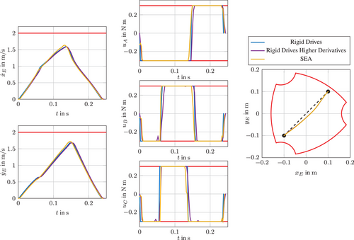
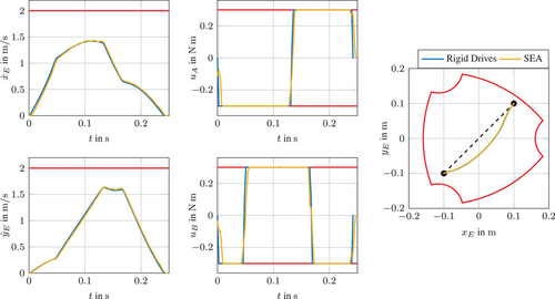
To show the validity of our approaches, for all cases the TOCP connecting the initial position z 0 T = [ 0.1 , 0.1 ] m ${\mathbf{z}}_{0}^{T}=[-0.1,-0.1]\;\mathrm{m}$ and terminal position z E T = [ 0.1 , 0.1 ] m ${\mathbf{z}}_{E}^{T}=[0.1,0.1]\;\mathrm{m}$ , exploiting the task space as effectively as possible, are solved. The comparison of the performance for the non-redundantly actuated PKM setups is depicted in Figure 5 and Figure 6 shows the equivalent for the redundantly actuated ones. The anticipated bang-bang behaviour of the motor torques is clearly visible and it can be seen, that similar results are achieved both, for the redundantly and non-redundantly actuated PKM. All moments of inertia and masses of the PKM can be found in [10]. For actuation torque limits u i , min = 0.3 Nm ${u}_{i,\min}=-0.3\;\mathrm{Nm}$ and u i , max = 0.3 Nm ${u}_{i,\max}=0.3\;\mathrm{Nm}$ each and for all spring stiffnesses c i = 1 Nm / rad ${c}_{i}=1\;\mathrm{Nm}/\mathrm{rad}$ are chosen. Physically meaningful limits for the remaining box constraints were applied and kept the same for all TOCP.
Details are in the caption following the image
Comparison of TOCP solutions between non-redundantly actuated PKM driven with rigid actuators and SEA. PKM, parallel kinematic mechanisms; SEA, series elastic actuators; TOCP, Time-optimal control problem.
Details are in the caption following the image
Comparison of TOCP solutions between redundantly actuated PKM driven with rigid actuators and SEA. PKM, parallel kinematic mechanisms; SEA, series elastic actuators; TOCP, Time-optimal control problem.

However, it is not entirely fair to compare the results of Section 3.1 to those of 3.2 and 3.3 as more constraints for the higher derivatives of the EE trajectory have to be applied for the TOCP of PKMs with elastic drives. When those same higher derivative constraints are also included in the TOCP of the PKM with rigid drives, faster trajectories for SEA-driven PKM are attainable, additionally solved and shown in Figure 6.

An Intel(R) Core(TM) i7-6700HQ CPU @ 2.60GHz CPU running Windows 10 was used for all computations. The terminal times T and computation times are listed in Table 1.

TABLE 1. Comparison of terminal and computation times.
Considered PKM Setup Terminal Time T Computation Time
Non-redundantly actuated PKM with rigid drives 0.242 s 2.10 s
Non-redundantly actuated PKM with SEA 0.246 s 39.17 s
Redundantly actuated PKM with rigid drives 0.237 s 2.03 s
Redundantly actuated with SEA 0.240 s 136.13 s
Redundantly actuated PKM with rigid drives considering higher EE-derivative constraints 0.243 s 2.54 s
  • Abbreviations: EE, end-effector; PKM, parallel kinematic mechanisms; SEA, series elastic actuators; TOCP, Time-optimal control problem.

5 CONCLUSION AND OUTLOOK

In this paper, a new approach on the time-optimal point-to-point trajectory planning for a planar SEA-driven PKM is introduced. Tailored time optimal trajectory planning problems for a planar parallel robot on the one hand, equipped with rigid drives and, on the other hand, driven by series elastic actuators, are proposed and the results are compared. It can be shown that by employing SEA for (redundantly-actuated) parallel robots similar or even faster results on the topic of time-optimality can be achieved. As for typical pick and place tasks the path-planning is done offline beforehand, the higher computational costs are of less concern. The next step will be to test the calculated trajectories on the real prototype and to compare the results. Future work will regard the time optimal control problem for cyclic pick and place like trajectories, further exploiting the loading of elastic elements and the tracking of energy consumption when redundantly actuated PKM are driven with SEA.

ACKNOWLEDGMENTS

This work has been supported by the “LCM K2 Center for Symbiotic Mechatronics” within the framework of the Austrian COMET-K2 program.

      The full text of this article hosted at iucr.org is unavailable due to technical difficulties.