Reconfigurable dipole receive array for dynamic parallel imaging at ultra-high magnetic field
Anton V. Nikulin and Felix Glang contributed equally to this work.
Abstract
Purpose
To extend the concept of 3D dynamic parallel imaging, we developed a prototype of an electronically reconfigurable dipole array that provides sensitivity alteration along the dipole length.
Methods
We developed a radiofrequency array coil consisting of eight reconfigurable elevated-end dipole antennas. The receive sensitivity profile of each dipole can be electronically shifted toward one or the other end by electrical shortening or lengthening the dipole arms using positive-intrinsic-negative-diode lump-element switching units. Based on the results of electromagnetic simulations, we built the prototype and tested it at 9.4 T on phantom and healthy volunteer. A modified 3D SENSE reconstruction was used, and geometry factor (g-factor) calculations were performed to assess the new array coil.
Results
Electromagnetic simulations showed that the new array coil was capable of alteration of its receive sensitivity profile along the dipole length. Electromagnetic and g-factor simulations showed closely agreeing predictions when compared to the measurements. The new dynamically reconfigurable dipole array provided significant improvement in geometry factor compared to static dipoles. We obtained up to 220% improvement for 3 × 2 (Ry × Rz) acceleration compared to the static configuration case in terms of maximum g-factor and up to 54% in terms of mean g-factor for the same acceleration.
Conclusion
We presented an 8-element prototype of a novel electronically reconfigurable dipole receive array that permits rapid sensitivity modulations along the dipole axes. Applying dynamic sensitivity modulation during image acquisition emulates two virtual rows of receive elements along the z-direction, and therefore improves parallel imaging performance for 3D acquisitions.
1 INTRODUCTION
Acceleration of imaging speed has been one of the most important and challenging aims in MRI within the last three decades.1-3 Approximately two decades ago, the landscape for rapid MRI changed dramatically with the invention of parallel imaging techniques such as SENSE, Simultaneous acquisition of spatial harmonics, GRAPPA, and others.2-4 Faster scanning is of utmost importance for all clinical MRI applications to guarantee feasibility and patient comfort, as well as to avoid potential subject motion and allow dynamic imaging of contrast changes (e.g., in angiography or functional MRI).
Fundamental problem of all acceleration techniques is the decrease in image SNR with increasing imaging speed.5 SNR of accelerated parallel imaging is inevitably decreased by √R, where R is the acceleration factor, compared to fully sampled non-accelerated scanning.2 An additional SNR penalty, characterized by the so-called geometry factor (g-factor), is caused by partially dependent or overlapping receive sensitivity profiles.2 A common way of minimizing the g-factor is increasing the number of elements in the RF array. Receive (Rx) array coils with an element count of 646 and higher, that is, 967 and 128,8 have been shown to substantially minimize g-factor values. However, the number of elements in the Rx-array is limited by the number of available Rx-channels of an MRI scanner. An additional limit of parallel imaging is the number of array elements that can be arranged around the object. Increasing the number of elements whereas keeping the same size of the array housing is associated with a corresponding decrease of the element's size, and, therefore, a decrease in the magnetic field penetration depth. The latter leads to an increase of the relative contribution of the noise produced by the array element itself (e.g., losses in conductor, electronic components, and radiation) in comparison to the sample noise, and hence, can compromise SNR.9
Recently, we proposed a novel type of parallel imaging acquisition based on the dynamic modulation of the sensitivity profiles of local RF receive coils at ultra-high field strength.10 Conventional parallel imaging relies on static sensitivity patterns of local receive coils, which is then used to accelerate image acquisition. This principle can be fundamentally expanded if these static sensitivity profiles are rapidly modulated during signal acquisition. Dynamic modulation virtually increases the number of array elements without decreasing their size, and therefore, improves parallel imaging and preserves elements' SNR. In previous works10 we presented a novel approach based on dynamically altering the receive sensitivity profile of surface loop elements using fast-switching positive-intrinsic-negative (PIN)-diodes or varactor diodes during acquisition. This shifts the current distribution along the loop length and leads to two distinct receive sensitivity patterns within a single receive element during signal reception.10 The spatial difference between the two distinct configurations within a single coil element decreases the g-factor compared to a single and static receive sensitivity profile. However, our previous design allows to alter the receive sensitivity profile only in the transverse plane, but not along the z-axis, which is allowed in the new design based on reconfigurable dipoles.
In this work, we proposed a novel elevated-end reconfigurable RF Rx array coil design based on short folded-end dipole elements.11, 12 The key idea of the folded-end dipole is moving the ends of the antenna, which generate the highest electrical field and lowest current, away from the tissue. As a result, the RF coil resonant frequency is much less sensitive to change of loading produced by variation of the human head size. In addition, using the folded-end dipole design, we load only the central part of the antenna where the current distribution is more uniform. This extends the distribution of the RF magnetic field in the longitudinal direction. The previously described shape of the folded-end dipole11, 12 is just one of the possible ways of making the folded-end dipole antenna more compact. In this work, to make the adjustment of the RF coil more convenient, we elevated the dipoles ends and bent them in the opposite direction compared to the original design.11 By switching between inductive and capacitive impedance inserted in both dipole's arms, we could increase or shorten the electrical lengths of each arm, and thereby, alter the receive sensitivity pattern of the dipole element by shifting the maximum of the current along the dipole length toward one or the other end of the dipole. Therefore, one physical element supports two asymmetrical RF field patterns, which can be switched within ˜1 μs using fast PIN-diodes. By dynamically switching the sensitivity profiles during acquisition, a single dipole element produces two virtual elements and significantly improves performance of parallel imaging for acceleration in planes, which include the head-to-feet (along the magnet axis) dimension. As a proof of concept, we developed and tested both using phantom and in vivo a novel reconfigurable 8-element receive RF dipole array coil for brain imaging at 9.4 T.
2 METHODS
2.1 The basic principle and design of the reconfigurable dipole antenna
Figure 1A shows the principle of the reconfigurable dipole antenna element, which is based on manipulation of the current distribution along the dipole length. For that purpose, we inserted a home-made electronically controlled switchable unit (SU) shown in Figure 1B (dashed line). This SU can change its impedance between capacitive and inductive, in each arm of the dipole depending on the applied DC voltage. During acquisition SUs are activated in such a way that one arm of the dipole has an inserted inductor while the other arm has a capacitor (Figure 1A). Because electrical lengths of the dipole arms become different, the electrical center (maximum of the current) moves toward the inductive impedance. This effect was shown previously in fractionated dipoles.13 The effect was used to adjust the electrical length of the dipole while keeping the physical length unchanged. As a result, the maximum of the RF magnetic field generated by the dipole also moves from the center of the dipole to the middle of the left or the right arm. By dynamically altering the dipole's sensitivity profile during the MRI acquisition, one can reduce the g-factors and therefore, improve accelerated 3D imaging.
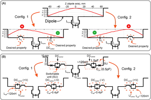
Figure 1B shows the proposed design of the reconfigurable dipole element. In this design, electronically controlled SUs based on PIN-diodes are inserted in each arm of the dipole. If the PIN diode is shorted (positively biased), the impedance of SU becomes inductive, which effectively increases the dipole electrical length. When the PIN diode is negatively biased, the impedance of the capacitors compensates the inductive impedance and the whole impedance of SU becomes capacitive, which corresponds to a decrease in the electrical length.
2.2 Electromagnetic simulations
In simulations, we considered an array of 8 elevated-end dipole11 elements equally distributed around a cylindrical surface with diameter of 210 mm as shown in Figure 2A. Each dipole had a “loaded” (closest to the sample part of the dipole) straight part of 130 mm and 10-mm elevated-ends placed at the height of 22 mm from the flat part of the dipole. The total length of the dipole antenna measured 150 mm. In the middle of each dipole, we placed the 50 Ω feeding port and the matching circuit as shown in Figure 1A. The flat parts of the dipoles were modeled as planar copper (lossy copper: σ = 5.8 × 10⁷) strips of 0.035 mm in thickness and 5 mm in width. The elevated-ends of each dipole were modeled using lossy copper wire with 1.5-mm radius. In the middle of one arm in each dipole we placed an inductor of 120 nH, whereas a capacitor of 0.5 pF was placed in the opposite arm (Figure 2A). Each capacitor also included a series inductor of 1 nH and resistor of 0.08 Ω. The dipoles were equally distributed around the FR4 (CST Studio Suite 2021 material library: εr = 4.3; tg δ = 0.025) holder of 210 mm in diameter, 2 mm in thickness, and 265 mm in length.
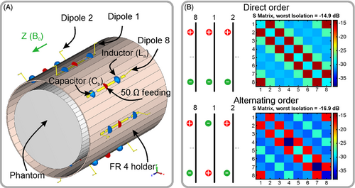
To simulate the RF coil, we used the frequency domain solver of the commercial software CST Studio Suite 2021 (Dassault Systèmes). The mesh optimization was performed at 400 MHz with 15 to 20 optimization passes. The convergence threshold was set to 0.02 as all s-parameters criteria. The simulations of the 8-elements array were performed in the frequency range of 380 to 420 MHz with 15 frequency points. The number of mesh cells was in the range of 378 to 640 thousand tetrahedrons. The coil was simulated in the presence of a homogeneous cylindrical phantom (εr = 58.3, σ = 0.64 S/m at 400 MHz) of 170 mm in diameter and 200 mm in length. In addition, we tested two different driving scenarios of the dipoles (Figure 2B). These scenarios are called “direct” and “alternating” order. In the “direct” driving scenario, all dipoles are switched in the same manner (i.e., all inductive impedances are active at the bottom or top part of the dipoles) whereas capacitive impedances are active at the opposite part. In the “alternating” scenario, all dipoles are switched in the way that when the first dipole has the inductive impedance at the top part and capacitive at the bottom, the next dipole has the opposite configuration.
To tune and match each dipole to 400 MHz (1H frequency at 9.4 T), we used co-simulations (CST Schematic). Depending on the design (alternating or direct order) as shown in Figure 1B, each dipole was tuned in co-simulations by a series inductor Ltune in the range of 15 to 52 nH and matched by a parallel capacitor Cmatch in the range of 7.5 to 12 pF depending on the setup. The final circuit is shown in Figure 2A,B. After that, field combine task was performed to obtain the receive fields from all independent channels. The simulated maps were obtained from H-field monitors using an embedded CST macro. All field maps were obtained for 1 W of stimulated power at the coil input.
2.3 G-factor simulations
Parallel imaging in MRI leads to an inevitable SNR loss by a factor of √R compared to a full Nyquist-sampled acquisition, where R denotes the acceleration factor. The receive coil sensitivities, which are used to complement Fourier encoding, are not completely spatially independent. This leads to local noise amplification in the parallel imaging reconstruction, depending on the spatial patterns of sensitivity profiles, which is quantified by the so-called g-factor.2
We found previously10 that time-varying sensitivities bring the largest g-factor improvement if sensitivities are switched rapidly for every analog-to-digital converter (ADC) sample of a two-fold oversampled acquisition (i.e., during a k-space readout line). In this case, g-factors are identical to the hypothetical case of having all sensitivities of the dynamic configurations statically active as “virtual receive channels” at the same time. This can be seen as a form of time-division multiplexing.15-17
For assessing g-factors from electromagnetic (EM) simulations, in the present work, receive sensitivities were calculated from the simulated RF magnetic field as = (B1,x – iB1,y)*/218, 19 and used to form the encoding operator and calculate g-factors according to Eqs. (2) and (3).
2.4 Coil assembly
The dipoles were made of printed circuit board (PCB) and wires (Figure 3). In contrast to the original design,11 the dipole design did not include a closely located RF shield. As shown in the original work, the shield reduces SNR.11 The dipole PCBs were manufactured in our institutional workshop using FR4 printed circuit board (PCB: 020103E11, Bungard) of 0.5 mm in thickness. These PCBs were glued on a fiberglass holder made by Klaus Hoppe Werbetechnik Design. In the ends of each PCB we soldered elevated-ends held by 3D printed polyethylene terephthalate glycol (PETg with Ultimaker S5 from Ultimaker B.V.) standoffs. The final length of each fold was adjusted to tune the coil to 400 MHz. The surface-mount device (SMD) capacitors (SH-series, Exxelia SAS) were used. All inductors were self-made using 1-mm copper wire, 4 turns of 3.5 mm in inner diameter for the tuning circuit, and 8 turns of 3.5 mm in inner diameter for the switchable unit (Figure 3A,C). For the switchable unit we used PIN-diodes (MA4P504–1072; MACOM) with a carrier lifetime of 1 μs and capacitance of 0.5 pF. The PIN-diodes were driven by a home-build complementary metal-oxide semiconductor (CMOS) driver, generating voltage of −5 V and +5 V, connected via a 7.5 Ω resistor. The CMOS driver was installed to the control unit, which was connected to the coil as shown in Figure 3B. An optical-electrical converter was used to convert the optical triggering signal to the electrical signal supported by the CMOS driver. Optical converter and the control unit were powered using 6 V non-magnetic batteries (NP7-6S, GS YUASA Battery Germany). We used 330-nH RF chokes inductors (9230 Series; Bourns) and a 330-pF capacitor for RF-blocking (Figure 3A). The DC block capacitors of 330 pF were inserted after the matching circuit to avoid the DC in the low noise amplifier (LNA) path. Each dipole was connected through the cable trap to the receive interface with 8 LNAs (WMA9RD; Wantcom) as shown in Figure 3A.
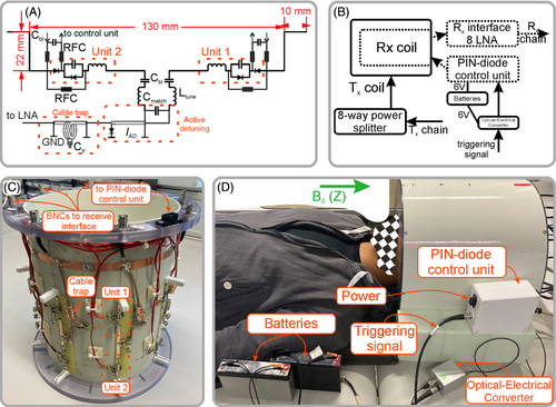
Active detuning was implemented similarly as previously described20 using the matching capacitor, PIN-diode (MA4P7461–1072, MACOM), and inductance of the short piece (˜50 mm) of the coaxial cable (K_02252_D-60, Huber+Suhner AG) as shown in Figure 3A. When the PIN diode was shorted, the short (the cable length less than quarter of the wave length) coaxial cable formed an inductor, which was adjusted by changing the length of the cable. The inductor placed across the matching capacitor formed a high-impedance parallel resonance circuit inserted between the halves of the dipole, and the coil was detuned.
As a transmit-only coil, we used a surface loop array of 8 elements (Figure 3D), wherein all closest elements were transformer decoupled.21 The array also included a cylindrical RF shield. The loops had a length of 130 mm, width of 100 mm, and were uniformly distributed around a cylindrical housing of 280 mm in diameter. The transmit coil was driven (Figure 3B) using a home-built 8 way-splitter with 45° between adjacent elements, which produced a circularly polarized mode. Specific absorption rate safety evaluations of the experimental setup for in vivo experiments were conducted in agreement with regulations of the local ethics committee.22 A photo of the entire setup of transmit-only coil and receive coil is shown in Figure S1.
2.5 MR imaging
Data were acquired on a 9.4 T human whole-body MR scanner (Siemens Healthineers) using a 3D RF and gradient echo sequence (TR = 20 ms, TE = 8 ms, flip angle = 10°, slab-selective excitation, matrix size 200 × 200 × 60, FOV = 220 mm × 220 mm × 120 mm, resolution 1.1 mm × 1.1 mm × 2 mm, 20% slice oversampling, resulting in an acquisition time of 4 min 48 s).
A map of the transmit array was recorded using a centric-reordered 3D saturated single-shot turboFlash (3DsatTFL) sequence23 (Figure S2).
Phantom measurements were performed in a homogeneous cylindrical phantom of 170-mm diameter, which contained a solution of 0.9698 g/mL Saccharose, 0.0307 g/mL NaCl, and 0.1% Dowicil, resulting in the same material parameters (σ = 0.64 S/m and εr = 58.3) as assumed in the simulations. In vivo data were acquired in a healthy subject after written informed consent and under approval of the local ethics committee.
The PIN diodes of the reconfigurable dipoles were controlled via the trigger output of the scanner system, which makes switching of the sensitivity configurations a user-programmable degree of freedom during MR data acquisition. As a reference, fully sampled k-spaces were acquired for both configurations without switching. Noise calibration scans for both configurations were performed by acquiring 200 repetitions of the same sequence as used for imaging, but with the transmitter voltage set to 0.
For imaging with dynamically switched configurations, 20-fold readout oversampling was applied for an ADC dwell time of 20 μs, which results in an effective dwell time of 1 μs and a bandwidth of 250 Hz/pixel. During the ADC blocks, configurations were repeatedly switched every 10 μs. Using this procedure, multiple Nyquist-sampled k-space datasets can be obtained by reordering the oversampled data. Each of these reordered datasets corresponds to a different time step in the repetitive switching dynamics, so that ideally half of them are weighted by one state of the receive array and half by the other. By averaging the respective images, multiplexed coil images of both receive array states are finally obtained. A detailed description of this method can be found in Glang et al.,10 where a graphical representation of the process is also given (Figure S1 of reference Glang et al.)10
2.6 Parallel imaging reconstruction and analysis
Noise decorrelation was applied to all datasets according to the noise covariance matrices as obtained from the noise calibration scans.14 Receive sensitivities from both configurations were obtained from the acquired fully sampled data via ESPIRIT,24 using the central 48 × 48 (PE1 × PE2) k-space lines. This algorithm captures the intensity variations among coil images because of and therefore, intrinsically compensates for and object signal dependences, which are the same in all channels. Parallel imaging performance was assessed by retrospective undersampling of the fully sampled k-spaces and subsequent SENSE reconstruction with the obtained sensitivity maps for both the two static cases and the dynamically switched case.
For all reconstructions, g-factors were calculated from the sensitivity maps according to Eqs. (1) and (2).
3 RESULTS
3.1 Electromagnetic simulation
We simulated two scenarios of dipole driving. In both scenarios, the resonant frequency of the array was adjusted to 400 MHz. In the first “direct” driving scenario, all dipoles are switched as shown in Figure 1B. In this case, we have obtained a mean reflection coefficient Sii of −29.49 dB and the worst isolation between closest adjacent elements of −14.9 dB (Figure 2B). In this scenario, because of symmetry, there is no receive field variation among the dipoles along the z-axis near the center of the cylinder, therefore, 3D acceleration is possible only in the switched configuration. As an alternative, we proposed to flip every second dipole to drive them in so-called “alternating” order (Figure 2B). This way of driving improved the isolation between the nearest neighbors. As a result, the average transmission coefficient between two adjacent elements was −16.9 dB, whereas impedance matching was −36.33 dB (Figure 2B).
Because electrical lengths of the dipole arms become different, the electrical center (maximum of the current) is moved toward the inductive impedance. As a result, the maximum of the current moves from the center of the dipole to the middle of the left or the right arm. Figure 4 shows the simulated |H|-field distribution of a dipole (130 mm in length) at a depth of 5 mm from the phantom surface. As seen in Figure 4, the field maximum follows the changes in the current distribution. Using this method, we can achieve a ratio of 1:0.4 between |H|-field picked in the opposite quarters (−31 mm and 31 mm from the dipole center) of the dipole arms. This current (H-field) difference leads to a corresponding change in (sensitivity pattern) field. The simulated maps in a.u. for each configuration are shown in Figure 4. Here, we normalized each map to its maximum. As seen in the figure, the field maximum moves from the center of the dipole (as in conventional dipole) toward the middle of each arm. Accordingly, measurements in a homogeneous phantom with a single dipole receive element (Figure 4) show two distinct spatial receive sensitivity patterns. By dynamically changing the receive field during the MRI acquisition, one can reduce the g-factors and therefore, improve accelerated 3D imaging.

In addition, we simulated case with lossy PIN diodes. In Figure S3 we showed maps for both cases, and as seen, the effect of losses is almost negligible.
3.2 G-factor simulations
Figure 5 shows simulated transversal and sagittal g-factor maps calculated for an array of conventional dipoles and a reconfigurable dipole array (Figure 5A) dynamically switched in the direct order for acceleration factor Rz of 2. Both arrays consisted of 8 elements uniformly surrounding the cylindrical phantom. Depending on the slice number along the z-direction, the improvement in g-factors varies (Figure 5B). Finally, the dynamic switching provided an overall improvement in maximum g-factor up to 263.1-fold and mean g-factor up to 9.81-fold for the acceleration factor Rz of 2. The array of conventional dipoles demonstrated unfeasibly high values of mean and maximum g-factors (Figure 5B) for acceleration in the z-direction because there is no field variation among dipole antennas along the z-direction in the center of the phantom. The same is true for the static direct driving. Therefore, we do not consider these two scenarios in further comparison. For the alternating order scenario, the z-acceleration can be used even without switching because the field varies among the coil elements in the z-direction.
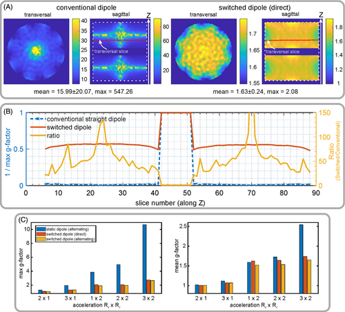
Hence, we compare g-factors for three scenarios including direct order dynamically switched dipoles, alternating order static and dynamically switched dipoles. In all three cases, we used 8-element dipole arrays loaded with the cylindrical phantom (Figure 2A). Figure 5C shows the maximum and mean g-factors for all three cases. An overall improvement of the switched over the static scenario can clearly be seen in Figure 5C. Among the studied designs, the design with switched dipoles placed in the alternating order shows the best results. Namely, it demonstrated 2.01-fold improvement for acceleration of 1 × 2 (Ry × Rz), 2.5-fold improvement for 2 × 2, and 4.02-fold improvement in case of 3 × 2 in maximum g-factor compared to the alternating order, but without switching. An improvement of 5% for 1 × 2, 12.4% for 2 × 2, and 54% for 3 × 2 is reported for the mean g-factors compared to the alternating order coil, but without switching. For in-plane acceleration (2 × 1 and 3 × 1), all coils show comparable values of g-factors. Comparison of two switched cases shows a small (3%) improvement in the case of the alternating scenario. Although this difference in g-factors is minor, because of improvement in isolations between the channels, the design of alternating order was considered for prototype assembling. Figure 5 presents only an example of imaging accelerated in the y-z plain. Because of the cylindrical symmetry of the simulated geometry, acceleration in x-z plain produces the same results.
3.3 Coil testing and image reconstruction
The final coil design is depicted in Figure 3. After assembling and fine-tuning on the bench, we tested the coil in the 9.4 T scanner on the phantom and in vivo.
To verify that the multiplexing procedure does not distort the obtained sensitivity patterns of the receive elements, in Figure S4 a comparison of non-switched and switched magnitude and phase maps is shown. It can be seen that the magnitude and phase patterns match for both switched and non-switched acquisitions.
Because the observation time per configuration is halved for the switched acquisitions compared to a non-switched acquisition of same duration, the SNR of the multiplexed configuration images is reduced by a factor of √2. However, by including all available data from the switched acquisition (i.e., averaging over both configuration images), a similar mean SNR as in the static cases is restored (Figure S5). This case is most relevant for parallel imaging reconstructions, where information from both configurations of a switched sequence is used simultaneously.
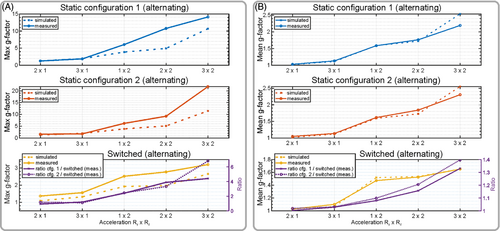
Figure 6 shows a comparison of simulated and measured g-factors all obtained using the developed 8-element array loaded by the cylindrical phantom. We evaluated two static configurations 1 and 2, and the dynamically switched configuration. In all three cases dipoles were arranged in the alternating order. The difference between configurations 1 and 2 is that inductors and capacitors at the ends of dipoles are swapped with each other. For example, if in configuration 1, dipole 1 (Figure 2A) has an inductor at the right side and capacitor at the left side, in configuration 2, it has an inductor at the left side and capacitor at the right side. In addition, single channel images of each element for configurations 1 and 2 (Figure 1A) are shown in Figure S6. Figure 6A shows an evaluation of maximum g-factors. This evaluation demonstrates that the switched scenario yields following improvements in the maximum g-factor: 2.46-fold for acceleration of 1 × 2 (Ry × Rz), 3.32-fold for 2 × 2, and 4.41-fold for 3 × 2 compared to the static scenario. Figure 6B shows improvement in mean g-factors of 8% for acceleration of 1 × 2 (Ry × Rz), 15.7% for 2 × 2, and 33% for 3 × 2 compared to the static scenario. We report this improvement compared to the worst case among static 1 or 2 configurations (Figure 6).
3.4 In vivo imaging
In Figure 7, in vivo parallel imaging results are compared for the cases of two static configurations and the case of rapidly switched alternating configuration for different acceleration patterns. As seen in the figure, higher acceleration leads to increased g-factors (Figure 6B). Switching sensitivities yielded an improvement of maximum g-factors of 1.66-fold for 1 × 2 (Ry × Rz), 1.65-fold for 2 × 2, and 2.2-fold for 3 × 2 acceleration compared to the worst static configuration case (Figure 8). In terms of mean g-factor, the developed coil demonstrated an improvement of 7% for 1 × 2 (Ry × Rz), 11.8% for 2 × 2, and 21.5% for 3 × 2 acceleration compared to the static worst configuration case (Figure 8). Similar observations can be made when choosing the first accelerated direction as left–right instead of anterior–posterior, this is, Rx × Rz acceleration (Figures S7 and S8).
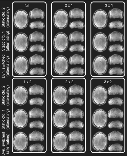
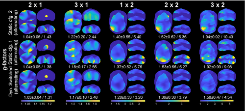
Figure 9A shows the g-factor obtained in vivo as a “violin” plot, where the peak value shows the maximum g-factor, and the width of each bar indicates the number of voxels of the corresponding g-factor across the entire acquired brain volume. Finally, the mean value for each case is shown by the black cross.
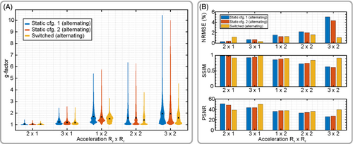
Figure 9B further compares the accelerated 3D SENSE reconstructions with the fully sampled ground truth. Here, the benefit of sensitivity switching is especially pronounced for high acceleration factors. For instance, in case of 2 × 3-fold (Ry × Rz) acceleration, switching reduces NRMSE by a factor of 4 (75% improvement), increases SSIM by a factor of 1.43 (43% improvement), and increases PSNR by a factor of 1.44 (44% improvement) compared to the better of the static cases, respectively.
4 DISCUSSION
In this work, we developed and evaluated a novel concept of a dynamic Rx RF array coil based on reconfigurable elevated-end dipoles11 for accelerated 3D parallel imaging of the human brain at 9.4 T. An array of conventional static dipoles arranged in a single row does not support 3D acceleration because there is no sensitivity variation among the dipoles along the z-direction (the axis of the magnet). In contrast, because of switching between the inductive and capacitive impedance placed in each arm of the reconfigurable dipoles, the receive sensitivity profile can be dynamically shifted along the z-direction during the acquisition phase, which provides two virtual dipoles. As a result, the developed one-row array coil has two effective (virtual) rows and is, therefore, capable of 3D acceleration.
We suggested two scenarios of dipole arrangement, namely “direct” and “alternating.” Despite having comparable parallel imaging improvement in both scenarios, the alternating order showed an improvement in isolation compared to the direct-order. This improvement in isolation can be important for further increasing the number of elements in a row. Finally, the dynamically switched alternating order dipoles demonstrated the best improvement of g-factors in vivo, that is, up to 2.2-fold for 3 × 2 (Ry × Rz) acceleration, compared to the static alternating order configuration. This improvement in g-factor allows using higher acceleration factors with the reconfigurable RF coil without additional g-factor penalty compared to the non-reconfigurable RF coil. For example, in case of 3 × 2 (Ry × Rz) acceleration, g-factor for the reconfigurable coil was comparable to the non-reconfigurable coil with a lower acceleration factor of 1 × 2 (Ry × Rz). Because of this improvement of g-factors, one could obtain comparable overall SNR for the static configuration (non-reconfigurable) accelerated by 1 × 2 (Ry × Rz) and switched configuration (reconfigurable) accelerated by 2 × 2 (Ry × Rz). As a result, when switching the sensitivities of the proposed RF coil one can shorten the acquisition time by a factor of 2 without additional SNR penalty. Such an improvement in scanning time can be particularly beneficial in high-resolution 3D anatomical brain imaging sequences like the popular MPRAGE26 or MP2RAGE.27
The proposed concept of reconfigurable receive dipoles can be also very useful for accelerated MRI at 7 T. This fact is of great importance taking into account recent clearances of two commercial 7 T MRI scanners for diagnostic imaging and a growing number of 7 T MRI machines over the world (more than 100). According to recent findings of the ultimate intrinsic SNR theory, maximum SNR deeper in the human body or near the brain center at 7 T and above can be obtained only by combining complementary conductive structures carrying different current patterns, for example, loops and dipole antennas.28, 29 Following these theoretical findings, we recently developed two novel 32-element dipole/loop combined array designs,20, 30 and wherein our new findings can be potentially applied to improve parallel imaging. For both dipole/loop designs, the 3D parallel imaging can be further improved by using reconfigurable dipoles that can effectively increase the number of virtual rows of dipoles to 2 (first design) or 4 (second design). Use of dipole antennas was also demonstrated for imaging of the human body at 3 T.31 Therefore, the developed technique of dynamic Rx dipoles can be also applied for 3 T human body imaging.
Comparing g-factors between simulation and phantom measurement (Figure 6), for the measured maximum g-factor value we have observed underestimation of our simulation by 18.3% to 40.4% depending on the acceleration factor. In contrast, we have observed good agreement between measured and simulated results in terms of mean g-factors. This can be explained by the fact that g-factor hot spots appear at the edges of the imaged object, and therefore, maximum g-factor values are very sensitive to the choice of image mask. For the mean value this problem is mitigated.
The ability to undersample a 3D k-space in the two phase encoding directions (e.g., acceleration patterns like 2 × 2) is favorable for parallel imaging compared to accelerating along a single direction (e.g., 4 × 1), as the former makes use of the spatial coil sensitivity information in two instead of only one direction.32
As a drawback, the presented setup requires additional electronics for controlling the PIN diodes and wires delivering the DC to the dipoles. These wires can interact with the dipoles and therefore, have to be mounted with care. However, this can be improved, for example, if the DC is guided through the same coaxial cable connected to the dipoles. This might reduce the number of extra wires and minimize residual interactions with electronics. EM simulations suggest that the proposed reconfigurable dipoles are applicable also at 7 T and higher fields such as 10.5 T and 11.7 T, but become less efficient at lower fields.
The proposed approach of dynamically switched Rx-elements is applicable to all types of MRI sequences, as the switching provides an additional degree of freedom during image encoding. In the present case, coil sensitivity variation along the z-axis is achieved by the two reconfigurable states of the dipoles, whereas in-plane (x/y) there is almost no sensitivity variation between the configurations. Consequently, for the in-plane acceleration, dynamic switching provides no significant benefit over static configurations. However, more advanced reconfigurable receive dipole element geometries can allow modulation of both in-plane and along the z-axis to further improve parallel imaging performance.
5 CONCLUSIONS
We presented an 8-element prototype of a novel electronically reconfigurable dipole receive array that permits rapid sensitivity modulations along the dipole's axes. Applying dynamic sensitivity modulation during image acquisition emulates two virtual rows of receive elements along the z-direction, and therefore, improves parallel imaging performance for 3D acquisitions. As a result, the dynamically switched dipoles demonstrated a significant improvement of g-factors in vivo, that is, up to 2.2-fold for 3 × 2 (Ry × Rz) acceleration, compared to the static configuration.
ACKNOWLEDGMENTS
Financial support of the Max-Planck-Society, the European Research Council Advanced Grant “SpreadMRI” (834940), and DFG (Grant SCHE658/12) is gratefully acknowledged. The authors express their gratitude to Rui Tian for helping with the experimental setup. Open Access funding enabled and organized by Projekt DEAL.


