A Linear Connected Printed Inverted-F Antenna Array for 5G mm-Wave MIMO Applications
ABSTRACT
In this study, a linear connected printed inverted-F antenna (PIFA) array (LCPA) configured for a multiple-input multiple-output (MIMO) system is presented for use in 5G mm-wave applications. The design is compared with conventional antenna arrays to highlight the advantages of the proposed approach. Specifically, the proposed system consists of a four-element MIMO antenna array, where each element incorporates eight individual PIFAs, collectively forming a linear connected printed inverted-F antenna (LCPA) structure. To facilitate excitation of each LCPA, a tapered T-junction 1 × 8 power divider/combiner is employed. The LCPA is specifically designed to operate at a frequency of 28 GHz, suitable for high-frequency 5 G commu- nication. Experimental measurements show that the impedance matching bandwidth of the antenna spans 1 GHz, from 27.5 to 28.5 GHz, with a −10 dB return loss, indicating effective resonance within this frequency range. The entire antenna array is fabricated on a substrate material, R0-4350B, with a total size of 130 mm by 68 mm and a thickness of 0.76 mm. This compact design, being single-layered and simple in its structural layout, makes it ideal for integration into mobile handheld devices, where space is a critical constraint. Overall, the proposed design offers a high-performance, efficient solution for MIMO antenna systems in 5G mobile communication applications.
1 Introduction
Enhancement in data rates is an important aspect of the modern research in the mobile commu- nications. Currently, mm-wave bands, more specifically 28 GHz band, have been assigned to be used for the fifth generation (5G) mobile communication. Due to high-frequency operation, a large bandwidth can be used which, in turn, provides a significant improvement in data rates. Moreover, multiple-input multiple-out (MIMO) can further improve channel capacity by increasing the number of antennas [1, 2]. In this study, a wideband and compact design based on mm-wave bands and MIMO antenna system by utilizing the concept of linear connected antenna arrays is presented. Connected antenna array could be a suitable solution because of its compact size, wide bandwidth, low cross-polarization, and high gain characteristics.
Concept of connected antenna arrays (CAAs) was first presented in 1965 by Wheeler, namely Wheeler current sheet for phased-array antenna [3]. CAA based on dipole and slot antennas were presented for wideband at lower frequencies for radar applications [4, 5]. The main focus was to achieve wideband and low cross-polarization. Recently, slot-based connected antenna arrays were also presented for mobile applications with MIMO configurations [6, 7]. Moreover, circular and linear connected antenna arrays based on Vivaldi antenna and patch antenna, respectively, also presented in [8, 9] for wideband applications.
As for upcoming 5G technology, many works on antenna arrays have been proposed recently for mobile device [10-17]. In [10], a 16-element patch antenna array was reported for handset at 28 GHz. A single array using double substrate with overall size of 17.45 × 99.2 mm2 was presented with high gain values. Parasitic patches were used to enhance the gain. Another, patch antenna array based on EBG and superstrate was reported in [11] for 5G applications. The usage of EBG and superstrate makes the antenna structure complicated for fabrication. Moreover, antenna array based on slot antenna was presented in [12] at 28 GHz. Three sub-arrays were used to generate three different beams. To improve the channel performance, a MIMO antenna system was reported in [13]. It was based on quasi yagi-uda antenna at mm-waves. Two different set of antennas were used to have MIMO configurations. Finally, a fixed beam single antenna array designs for 5G applications were also reported in [14-16].
It is concluded that, most of the CAA designs were based on slot, patch or dipole antennas operating at low frequencies [4, 5, 8, 9]. Moreover, above mentioned 5G antennas have either, single antenna array configuration with multiple substrates [10, 11] or single antenna array with fixed radiation patterns [14-16]. Therefore, this study aims to present, compact, single-layered and wideband antenna array design with MIMO configuration to have pattern diversity at 28 GHz.
In this paper, using connected antenna array principle, a new design is presented based on printed inverted-F antenna (PIFA) for 5G MIMO applications. The main contribution lies in the integration of PIFA as a connected antenna array which has never been presented in the literature according to author's best knowledge. Furthermore, a comparison of linear connected and conven- tional PIFA array is studied to show the features of linear connected PIFA array (LCPA). Then, four-element MIMO configuration based on LCPA is realized at 28 GHz to support MIMO communication. The proposed design has a peak gain of 12 dBi and efficiency is more than 80% in the whole covered band (27.5−28.5 GHz).
2 Proposed Four-Element MIMO Antenna Array Structure
The proposed structure is designed on a double layered commercially available substrate RO-4350B with overall dimensions of 130 × 68 mm2 (ϵr = 3.48, tan δ = 0.004, and thickness t = 0.76 mm). In Figure 1a, four-elements of MIMO antenna system along with power dividers are loaded along the four sides of the substrate on the top layer, while the system ground plane is printed on the bottom layer. Four rectangular slots with the size of 47.5 × 5 mm2 are etched from the ground plane. These slots provide ground clearance to four-element of MIMO antenna system. Separation and location of four elements are optimized to have low mutual coupling, while providing enough space to integrate 3G/4G antennas as shown in Figure 1a. A fabrication prototype is also made to validate the proposed design. The photograph of fabrication prototype is shown in Figure 7b.
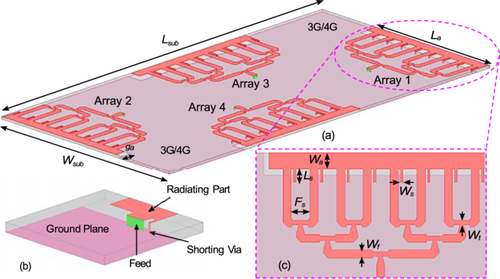
The proposed design is realized based on the combination of two basic concepts. Firstly, an ordinary printed inverted-F antenna (PIFA) is designed at 28 GHz. Secondly, eight PIFAs are connected directly with each others based on the theory of connected antenna arrays to form a linear connected antenna PIFA array (LCPA). The initial simulated results were presented in [17]. A detailed analysis and results of the proposed design are shown in the following section.
3 Results and Discussions
3.1 PIFA Unit Element Analysis and Results
The considered simple PIFA consists of four main parts: radiating part, ground plane, feed point, and shorting via. Figure 1b shows the structure of PIFA. It resonates at 28 GHz and fed through 50 Ω lumped port in the simulation environment. The width of the radiating part is 3.5 mm, and total length (including shorting via) is 7.17 mm (0.67λ0, where λ0 is the free-space wavelength at 28 GHz). The optimization and impedance matching is achieved through the length of the antenna, shorting via, and spacing (Ws).
3.2 Comparison of Connected and Conventional Eight-Element Linear PIFA Array
To demonstrate the characteristics of connected antenna array, it is important to have a comparison between connected and convention antenna array first. An array of conventional 4-element PIFA is shown in Figure 2a. The total aperture of that array AL × Aw = 44.5 × 7 mm2 where the spacing (Sa) between each element is 5.1 mm (0.48λ0). It covers frequency 24.4–30.2 GHz band with maximum gain of 10.2 dBi at 28 GHz.
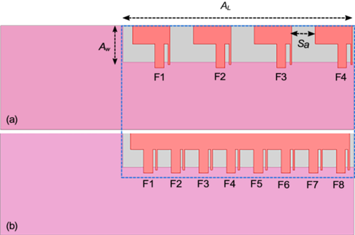
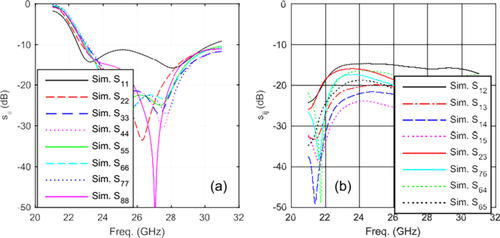
Now, utilizing the similar aperture size of AL × Aw, eight-antenna elements are connected directly with each others based on the theory of connected antenna arrays (CAA) where Sa = 0 (There is no spacing between array elements that allows to add more elements in same aperture size). CAA can be connected directly with each others [7, 8] or via inserting connection lines [9]. The geometry of this configuration is shown in Figure 2b. It covers frequency 23–30.5 GHz band with maximum gain of 14.3 dBi at 28 GHz. This configuration gives extra 1.7 GHz bandwidth and 4.1 dBi gain compared to conventional PIFA array utilizing the same aperture. For that reason, connecting PIFAs together provides advantage of wider bandwidth and high gain values. Although all antenna elements are connected with each others, but due to shorting via connected with each element allows to have low coupling between adjacent elements. The reflection coefficient curves are shown in Figure 3a and isolation curves are shown in Figure 3b. The isolation between all antenna elements is more than 15 dB.
3.3 Analysis and Optimization of Eight-Element Linear Connected PIFA Array
In this part, main focus is to design an optimized eight-elements linear connected PIFA array (LCPA) along with 1 × 8 power divider. Figure 1b shows LCPA, while Figure 1c shows LCPA along with power divider. The length of the LCPA is La while the width is Wa. The power divider is tapered T-junction, which is used to excite the LCPA. The spacing between the feeding arms (F1–F8) is Fs. The optimized LCPA covers 27.5–28.5 GHz band with 1 GHz bandwidth and it has a maximum gain of 12.5 dBi. The gain and bandwidth are reduced due to lossy power divider. However, these values satisfy the requirement of 5G.
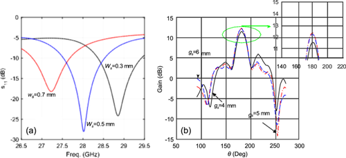
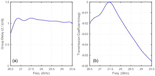
A parametric analysis is done to make the design compact and suitable to fulfil the requirements of 5G application where wide bandwidth and high gain values are needed. During parametric analysis, it is observed that changing the value of ground clearance (gs) changes the gain values because ground plane acts as a reflector and push the beams towards broadside. Results are shown in Figure 4b for different values of gs. Maximum gain value is achieved 12.3 dBi when gs = 5 mm and hence is fixed for the design. However, the width of the shorting via (Ws) and spacing between shorting via and feed line do affect the reflection coefficient because both of them contribute in the total length (Ls) of the LCPA and hence change the reflection coefficient. Results for different values of Ws are shown in Figure 4a. When Ws = 0.5 mm the total length of the LCPA (Ls) is equal to 45.8 mm, LCPA resonates at 28 GHz, while when Ws = 0.7 the (Ls) is equal to 47.36 mm, LCPA resonates at 27.2 GHz. All optimized parameters are the following: Lsub = 130, Wsub = 68, La = 45.8, Wa = 2.5, Ws = 0.5, Fs = 4, Ls = 3, Wt = 0.91, Wf = 1.72, all values are in millimetres. As part of the parametric study and optimization process, the transmission function and group delay variance of the antenna array in frequency domain are investigated in the simulation environment. In the simulation setups, another copy of the antenna array with identical geometry is generated and mounted in a mirror-symmetrical manner, with 200 mm distance to the original antenna in the far-field region. Both antenna arrays are orientated by pointing the maximum radiation direction to each other. As shown from Figure 5, the antenna array show ±0.1 nS variance of group delay, and less than 0.04 dB of transmission coefficient over the operating frequency from 27.5 to 28.5 GHz. Those values indicate a good signal fidelity of the designed antenna array in the pulse response.
3.4 A 4-Element MIMO Antenna System of Eight-Element Linear Connected PIFA Array
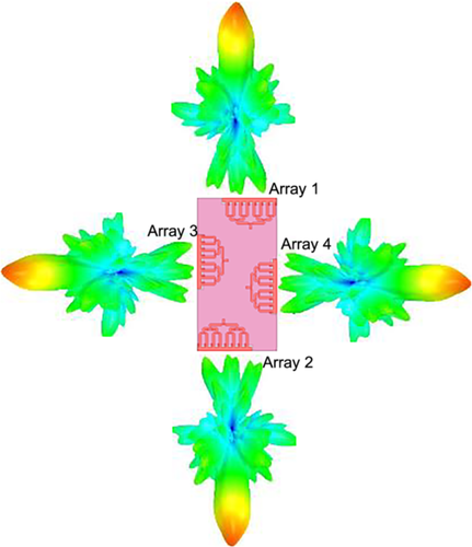
The geometry of the proposed 5G four-element MIMO antenna system (Array 1–Array 4) is shown in Figure 1. Four slots are etched in the ground plane on the bottom layer to make ground clearance for Array 1–Array4. The total area of the ground slot (rectangular slot) which is occupied by the single LCPA is only 47.5 × 5 mm2. That rectangular slot is located on the side of the substrate for each array that means a lot of free space is available for installation of other electronics, battery and LCD in mobile phones. In addition, integration of 3G/4G antennas can also realize as shown in Figure 1a. Then, four arrays (Array 1–Array 4) are placed on the top layer of the substrate over the four ground etched rectangular slots. Such configuration is used to have low mutual coupling between MIMO elements and provide best spatial diversity performance. Figure 6 shows radiation patterns for Array 1–Array 4, all 3D beams pointing at different directions.
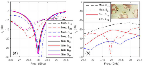
The S-parameters are measured using 40 GHz FieldFox VNA, while the radiation patterns are measured using 3D near-field chamber. The reflection coefficients (simulated and measured) of the 5G MIMO antenna system are shown in Figure 7a. Results shows that the proposed design covers a −10-dB impedance matching bandwidth of 1 GHz from 27.5 to 28.5 GHz. This covered bandwidth satisfy the requirement of 5G at 28 GHz band. Nevertheless, there is still room for additional bandwidth expansion despite the essential performance criteria for 5G communications. Crucially, it avoids the requirement for complex feed networks or multilayer structures by striking a compromise between performance and size. To expand the operating bandwidth, future iterations may look at different feed network architectures or different substrate alternatives. The isolation curves are shown in Figure 7b. The minimum isolation between Array 1 and Array 3 is 30 dB. As expected a high isolation is observed in the proposed design which is primarily attributed to the spatial arrangement of the antenna elements. Specifically, the antennas are placed orthogonally and/or at a half-wavelength (λ/2) spacing from each other, which is a well-established technique for reducing mutual coupling. This design approach effectively minimizes surface current interaction and coupling between adjacent elements at mm-wave frequencies.
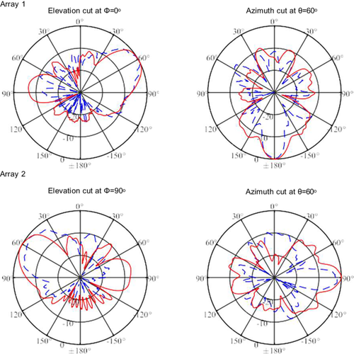
The normalized simulated and measured radiation patterns of the proposed design are shown in Figure 8 for Array 1 and Array 3 at 28 GHz for azimuth and elevation plane at different cut angles. It should be noted that both arrays have different directional beams that show good performance and hence leads to have spacial diversity and low correlation coefficient values. Due to symmetry in design, we have shown only for Array 1 and array 2, while the radiation patterns for Array 2 and Array 4 have similar radiation patterns, however pointing 180◦ different directions compared to Array 1 and Array 3, respectively. The envelope correlation coefficient (ECC) is also calculated using 3-D far-field radiation patterns based on formula given in [18] to show further MIMO characteristics. Table 1 shows ECC values at different frequencies between different arrays. All values are less than the acceptable value of ECC that is 0.5. The diversity gain is also calculated using . Using measured values of ECC at the 28 GHz between Array 1 and Array 2, the DG is equal to 9.9902 which shows acceptable value for MIMO operations [18].
| Frequency (GHz) | Array 1 and Array 2 | Array 1 and Array 3 | Array 3 and Array 4 | Array 2 and Array 3 |
|---|---|---|---|---|
| 27.5 | 0.0412 | 0.0312 | 0.0482 | 0.0513 |
| 28 | 0.0443 | 0.0277 | 0.0535 | 0.0433 |
| 28.5 | 0.0391 | 0.0445 | 0.0453 | 0.0433 |
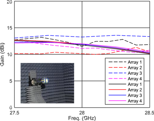
The simulated and measured maximum gain for Array 1–Array 4 are presented in Figure 9. The maximum value of the measured gain at 28 GHz is 13 dBi for Array 3, while other arrays have more than 10 dBi. The difference between simulated and measured gain is around ±1.5 dBi which is due to the fabrication process, soldering of connectors, and errors during the measurements. A photograph of the measurement setup in the near-field chamber is also shown in Figure 9.
The proposed MIMO antenna system is compared with the existing literature [19-24], and it is provided in Table 2. The proposed antenna design demonstrate balanced various metrics across various key performances: such as gain, isolation, size and bandwidth. The proposed system has the compact size of 130 × 68 mm* and a single antenna footprint is just 47.5 × 5. Despite compactness the design achieves a gain of 10 dBi outperforming while maintaining size efficiency. The antenna offers a 1 GHz bandwidth at 28 GHz better than designs where size is compromised while achieving the bandwidth. Importantly, the proposed design has good isolation of 25 dB, which depend on sophisticated antenna placement which improves over all MIMO functions and effectively reduces mutual coupling. The proposed antenna is specifically designed for mmWave 5G applications, in contrast to some other related works that concentrate on sub-6 GHz or large-area solutions. It offers the balance of high gain, compactness, and isolation—all of which are necessary for effective integration into next-generation wireless communication devices.
| No. | Single antenna aize(mm2) | MIMO antenna Size (mm3) | Bandwidth (GHz) | Isolation (dB) | Gain (dBi) |
|---|---|---|---|---|---|
| [19] | 10 × 10 | 30 × 30 × 1.6 | 3.5 | 30 | 7.1 |
| [20] | 15.8 × 17.2 | 17.2 × 62 × 0.8 | 3.5 | 25 | 19.6 |
| [21] | 16.80 × 13.52 | 30 × 30 × 1.6 | 3.07 | 58 | 7.41 |
| [22] | 55 × 115 | 55 × 115 | 1.0 | 26 | 7.95 |
| [23] | 100 × 40 | 100 × 60 × 0.76 | 1.565 (4G), 1.3 | 10 | 3 (4G), 8 |
| (5G) | (5G) | ||||
| [24] | 10 × 12 | 24 × 10 | 0.88 | 30 | 8.75 |
| This study | 47.5 × 5 | 130 × 68 × 0.76 | 1.0 | 25 | 10 |
4 Conclusion
In this study, a LCPA with MIMO configurations is presented for 5G mm-wave applications. A comparison of connected and conventional PIFA array is also studied. A prototype having four LCPA is built and tested. A good agreement between simulated and measured results is observed. The covered −10-dB impedance matching bandwidth is 1 GHz from 27.5−28.5 GHz. The measured maximum gain value observed is to be 10 dBi. While the proposed design meets key 5G requirements, future enhancements such as wideband feed networks or alternative substrates may be explored to further extend the operational bandwidth for future work.
Acknowledgments
Open access publishing facilitated by The University of Queensland, as part of the Wiley - The University of Queensland agreement via the Council of Australian University Librarians.
Open Research
Data Availability Statement
Data sharing not applicable to this article as no datasets were generated or analysed during the current study.


