A Super-Formula-based compact ultra-wideband antenna and its application to indoor real-time positioning systems
Abstract
A Super-Formula-based compact ultra-wideband (UWB) printed monopole antenna is proposed in this paper. The presented design is implemented by using inexpensive FR-4 laminates, and is optimized so as to enable excellent radio frequency performance in terms of impedance matching, realized gain, total efficiency, radiation pattern characteristics, maximal group delay variation, and system fidelity factor (SFF), while covering the Federal Communications Commission UWB channel 5, from 6.24 to 6.74 GHz, and channel 9, from 7.74 to 8.24 GHz. The proposed antenna solution has been characterized both passively and actively using a commercially available indoor real-time positioning system, which relies on the phase-difference-of-arrival algorithm. The collected measurement results demonstrate the high accuracy in real-time positioning achieved with the developed antenna both in terms of distance and angle.
1 INTRODUCTION
Ultra-wideband (UWB) is an IEEE 802.15.4 standard-based technology that is optimized for real-time positioning applications.1 UWB radio systems make use of the frequency spectrum from 3.1 to 10.6 GHz and can enable a location accuracy in the range of 10 cm for different services such as access control, asset tracking, peer-to-peer communications, and contact tracing, in both indoor and outdoor operative scenarios.2 Two-way ranging based on UWB signal processing, such as time difference of arrival (TDoA) and phase difference of arrival (PDoA), features significant benefits in terms of higher precision and larger coverage range when compared to alternative positioning techniques, which rely on Wi-Fi, Bluetooth, or RFID solutions.3
A key component of UWB systems is obviously represented by the antennas. Spline technology has been used for the design of both linearly4 and circularly5 polarized UWB antennas. On the other hand, the Super-Formula proposed by Gielis6 allows describing a wide variety of complex profiles and curves that are found in nature. By properly selecting the geometrical parameters appearing in the Super-Formula, one can generate very diverse shapes. The formula was introduced as a generalization of the super-ellipse or Lamé equation. It has been broadly applied to antenna design in recent years, including three-dimensional dielectric lens7-9 and printed radiating structures,10, 11 for wireless communications and remote sensing.
In this paper, a compact antenna design with Super-Formula-based geometry is presented and optimized in terms of impedance matching, gain, radiation pattern, maximal group delay variation, and system fidelity factor (SFF) characteristics across the UWB channel 5, from 6.24 to 6.74 GHz, and the UWB channel 9, from 7.74 to 8.24 GHz, respectively. Passive and active measurements taken on a physical demonstrator of the developed antenna design in combination with a real-time positioning system are carried out and commented on.
2 THE ANTENNA DESIGN
2.1 Parameter study based on Super-Formula
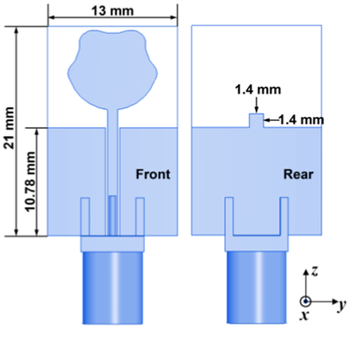
Different shapes can be easily generated by changing the parameters appearing in (1). Enabling a robust antenna performance in the UWB channel 9 is rather challenging as compared to the coverage of channel 5. Therefore, an extensive parameter study, not presented here for sake of brevity, has been carried out for the enhancement of the antenna characteristics in channel 9. The resulting optimized super-shaped monopole with geometrical parameters a = 5.856, b = 1.2, n1 = −8.17, n2 = 0.913, and n3 = 3.762 features the best impedance matching properties and the minimum group delay variation across both frequency bands of interest, simultaneously, with a significant performance improvement over a conventional circular monopole antenna12 having the same area.
2.2 Group delay and SFF
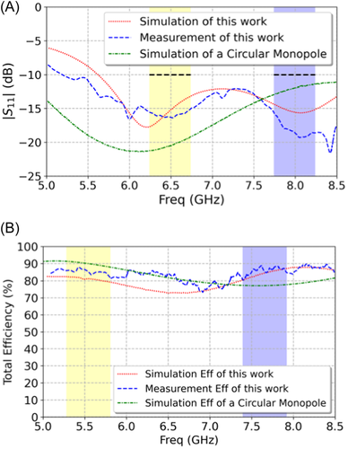
In real-time positioning systems, such as PDoA and TDoA, the maximum group delay variation is typically specified to be smaller than ±100 ps. To minimize the group delay variation versus frequency displayed by the presented antenna solution, an additional metal stub has been introduced on the rear side of the relevant radiating flare, as shown in Figure 1. In this way, it is possible to well condition the current flow around the feed point of the monopole across the entire frequency range of operation. Through parameter study of the antenna performance as a function of the length L of the aforementioned stub, it has been found that optimal characteristics are achieved with L = 1.4 mm. Under such conditions, the simulated maximum group delay variations are ±57.5 and ±96.5 ps in channels 5 and 9, respectively. After optimizing the antenna geometry for minimum group delay variation in the frequency bands of interest, the return loss has been verified and confirmed to be well above the reference level of 10dB (see Figure 2).
The SFF was firstly introduced by Quintero et al.,14 and is defined as the maximum value of the cross-correlation between the reference input pulse and the received pulse signals. The SFF is useful to assess the effectiveness of a given UWB antenna by taking relevant frequency- and time-domain characteristics into account in a combined manner.13 In this research study, the SFF has been assessed numerically using a time-domain solver in combination with electric field probes, which are set every 15° in both the azimuth (φ) and elevation (θ) planes at a distance of 50 mm from the physical center of the antenna. Such distance has been selected to be larger than 2D2/λ at 8.24 GHz, with D being the maximal antenna dimension and λ denoting the relevant free-space wavelength, so as to ensure that the measurement probes are in the far-field region. The orientation of the probes in both planes of observation is set according to the antenna polarization, to measure the dominant electric field component. Consequently, it has been found that the SFF is larger than 0.9 along the entire azimuth plane, thus making the proposed Super-Formula-based antenna a suitable solution for UWB applications, such as real-time positioning systems of interest, in this study.
3 ANTENNA MEASUREMENT RESULTS
3.1 Passive measurements
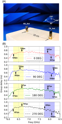
The return loss and group delay of the antenna have been measured on a physical prototype using a Keysight E5071C vector network analyzer (VNA) and with the device under test installed in a suitable anechoic chamber. A good agreement between simulated and measured return loss can be observed in Figure 2A. As shown in Figure 2B, the measured total efficiency of the antenna is above 77% and 84% in channels 5 and 9, respectively, this being in pretty good agreement with the numerical simulation results.
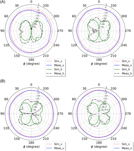
The radiation pattern characteristics of the presented antenna were evaluated using an MVG Starlab measurement system. In Figure 4, one can notice that the radiation pattern measurements nicely align with the numerical full-wave simulations, thus proving the azimuthally uniform radiation characteristics of the developed antenna solution, as well as the rather good pattern stability and consistency across a relatively broad frequency band.
3.2 Active measurements
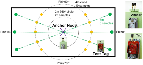
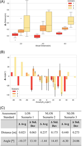
In our study, the anchor is realized by integrating two identical radiating elements on the same substrate as shown in Figure 5, where the adopted indoor testbench is sketched. To assess the positioning accuracy with sufficient resolution, 20 equally distributed test points are selected at a distance of 2 m between the tag and the anchor node, whereas the number of test points is reduced to 10 and 8 when the distance increases to 4 and 8 m, respectively (see Figure 5). Before the positioning measurements, the anchor node and the test tag have been properly calibrated. At each test point, the relevant measurement value is evaluated as the average of a continuous 10-s real-time track record. Three scenarios were characterized: (1) direct line-of-sight (LOS); (2) non-LOS (NLOS) with one person standing in between the node and the tag; and (3) NLOS with two people standing in between the node and the test tag. The statistics on the deviations seen between measured and actual geometric values of distance and angle are visualized and summarized in Figure 6. As compared to the most recently reported test data in,17, 18 the obtained results prove the effectiveness of the proposed Super-Formula-based UWB antenna design and superior performance in terms of positioning accuracy.
4 CONCLUSION
In this paper, a novel printed monopole antenna design for UWB applications has been presented. The geometry of the developed radiating structure is parametrized by means of the Super-Formula and optimized for excellent RF performance in the Federal Communications Commission UWB channels 5 and 9. Based on measurement results, it has been found that the return loss of the antenna is larger than 15 dB in both channels, while the total efficiency is above 77%, well in line with the numerical predictions by full-wave simulations. The antenna features azimuthally uniform radiation pattern characteristics. Furthermore, the measured maximum group delay variation has been verified to be smaller than ±100 ps in both UWB channels of interest. The antenna has also been characterized in combination with a commercial real-time positioning system in an indoor environment. The measured positioning accuracy has been found to be 2.3 and 23 cm in LOS and NLOS scenarios, respectively, which proves the superiority of the proposed technical solution in the most recently published literature.
Open Research
DATA AVAILABILITY STATEMENT
Research data are not shared.


