MSLattice: A free software for generating uniform and graded lattices based on triply periodic minimal surfaces
Abstract
Nature-inspired materials based on triply periodic minimal surfaces (TPMS) are very attractive in many engineering disciplines because of their topology-driven properties. However, their adoption across different research and engineering fields is limited by the complexity of their design process. In this work, we present MSLattice, a software that allows users to design uniform, and functionally grade lattices and surfaces based on TPMS using two approaches, namely, the sheet networks and solid networks. The software allows users to control the type of TPMS topology, relative density, cell size, relative density grading, cell size grading, and hybridization between lattices. These features make MSLattice a complete design platform for users in different engineering disciplines, especially in applications that employ additive manufacturing (3D printing) and computational modeling. We demonstrate the capability of the software using several examples.
1 INTRODUCTION
In nature, many biological systems such as bone, wood, and marine sponge have a microstructure that consists of interpenetrating solid and void phases and exhibit a desirable combination of strength and lightweight necessary for support, mobility, and protection.1-3 Such materials influenced and promoted the emergence of the cellular materials field of study, which is concerned with synthesizing lightweight, energy absorbing, multifunctional, and strong materials, composites, and structures. Such materials are obtained by deliberately introducing voids in the bulk of solid material and can be classified based on their structure into stochastic (foams) or periodic (lattices) unit cells. Also, based on the unit cell's topology, cellular material can be classified into open-cell and closed-cell foams/lattices.4 The mechanical and physical properties of cellular materials depend on their topology. This structure–property relationship suggests that the mechanical and physical properties of cellular materials depend not only on the chemical composition of base materials but also on the geometric features of the unit cell or cells making the cellular material.
In recent years, advances in additive manufacturing (3D printing) facilitated the fabrication of cellular materials and reduced the limitations in fabrication associated with structural complexity. Synchronously, different design tools evolve to facilitate the design of complex structures and allow users to realize complex functional designs much easier. One design approach that attracted lots of interest is based on the mathematical representation of the cellular materials, in particular, the design of lattices based on triply periodic minimal surfaces (TPMSs). Because of their fascinating topologies and related geometrical features such as smooth shells, large surface area to volume ratio, and interpenetrating void networks, TPMS-based lattices have been proposed in recent years for a wide range of engineering applications such as scaffolds for tissue engineering and body implants,5-9 interpenetrating phase composites with tunable mechanical properties,10-19 functionally graded structural lattices,20 thermal management devices such as heat sinks21 and heat exchangers,22 soft robotics,19 catalytic substrates,23 feed spacers,24-27 moving bed biofilm reactors for wastewater treatment,28 static mixers for chemical processes,29 and lightweight structures for mechanical components.20, 30-40 TPMS can be represented using level-set approximation equations, which are a set of trigonometric functions that describe an iso-surface evaluated at an iso-value. Although several studies presented the mathematical models and examples of the generated lattices, the actual implementation is often not presented. The complexity of implementing the mathematical representation of the surfaces to create 3D models is a limitation that hinders a wider adaption of TPMS in deferent fields.
In this work, we recall the mathematical representation of TPMS-based materials and introduce a design tool that allows scientists, researchers, and engineers to generate uniform and functionally graded 3D printable models and surface meshes of TPMS-based lattices using two approaches, namely, the sheet networks and solid networks. This design package called MSLattice is freely available for the scientific and engineering community. The tool allows precise control of the type of TPMS topology, relative density (i.e., the ratio of lattice's density with respect to the density of the constituent material or, equivalently, the solid volume fraction), cell size, relative density grading, cell size grading, and hybridization between two different lattices. Furthermore, the software includes flexibility in allowing the user to design his own TPMS lattice based on level-set approximations.
2 METHODOLOGY
When a surface is characterized by having a mean curvature of zero at any point, it is referred to as a minimal surface.41 Also, when this surface is infinite and periodic in 3D, it is referred to as a TPMS. Several mathematical approaches were presented to describe the nodal coordinates that designate a minimal surface.42-44 However, the simplest and most used method is the level-set approximation approach.
2.1 Minimal surfaces
 ()
() ()
() ()
() ()
() ()
() ()
() ()
() ()
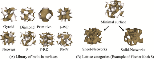
()
In these equations, X = 2απx, Y = 2βπy, Z = 2πγz, α, β, and γ are constants related to the unit cell size in the x, y, and z directions, respectively.
When the level-set equation is evaluated at a c = 0, the iso-surfaces split the space into subdomains of equal volumes. These subdomains can be controlled through the iso-value constant such that the volumes can be expanded or contracted by offsetting from the zero value in the normal direction or the opposite direction.
2.2 Uniform relative density
Creating a TPMS lattice material based on these zero-thickness surfaces is possible following two approaches. First is by considering one of the volumes divided by the minimal surface as the solid domain and the other as the void domain. This is done by considering the volume bounded by the minimal surface such that φ(x, y, z) > c or φ(x, y, z) < c to create a solid-network lattice. Second is by offsetting the minimal surface along its normal direction and against the normal direction to create a double surface by solving −c ≤ φ(x, y, z) ≤ c. The spatial nodes bounded by these two double surfaces construct the solid domain that represents a thickened shell/sheet-based lattice derived from the minimal surface. We refer to this lattice as a sheet-network lattice (see Figure 1B).
2.3 Functional grading of TPMS-based metamaterials
2.3.1 Relative density grading
 ()
() ()
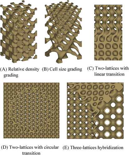
()For example, a linear grading is obtained by describing the iso-value as a linear function along one of the Cartesian coordinates such that c = Ax + B where A and B are constants. Similarly, any function can be used to control the relative density variation of the lattice structure (Figure 2A).
2.3.2 Unit cell size grading
The ability to mathematically control the topology of the lattice allows not only to perform spatial grading of the relative density but also to change the cell size in a certain direction. This permits varying the surface area and pore size at a constant relative density. The mathematical procedure to achieve cell size grading is detailed by Liu et al.46 and described in detail in the Supporting Information (see Figure 2B).
2.3.3 Cell type grading (multimorphology)
 ()
() ()
()where G(x, y, z) is the spatial coordinate set that describes the shape of transition between the different regions and k defines the width of that transition. The function G(x, y, z) can be any function in x, y, and z. For example, if the function G(x, y, z) = x, then the transition is simply taking place along the x axis (Figure 2C). If the function G(x, y, z) = x2 + y2 − t2, where t is a constant, then it defines a circular transition (Figure 2D). Note that if γ is constant such that 0 < γ < 1, then a new hybrid lattice is obtained without grading.
 ()
() ()
()where points xi lay in the ith subdomain, the ith substructure φi is assigned to the ith subdomain, n is the number of control points, and x denotes the 3D spatial coordinates (x, y, z). Figure 2E shows an example of a three-lattice hybrid structure obtained using Equations 13 and 14 (see also section 3 in the Supporting Information).
3 MSLATTICE DEVELOPMENT AND DEMONSTRATION
The mathematical equations presented in Section 2 have been implemented in Matlab and compiled into a simple-to-use graphical user interface (GUI). We refer to this GUI as MSLattice. MSLattice is a software package written and compiled into a standalone executable package. It runs on Matlab runtime library. The standalone package does not require Matlab to be installed. If the runtime library is not available on the user's computer, it will be downloaded during the installation of the MSLattice software. The installation wizards for Windows and Linux are provided in the Supporting Information and in the permanent GitHub repository https://github.com/MSLattice. The GUI consists of four main tabs (see Figure 3), namely, (1) Uniform TPMS lattices, (2) Functional TPMS grading, (3) Implicit functions, and (4) A simple STL viewer. The Functional TPMS grading tab contains two subtabs, namely, (a) Relative density grading tab and (b) Cell size grading tab. The Help menu provides a detailed description and documentation of each Tab.
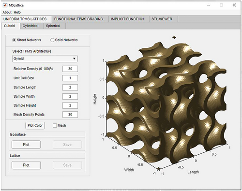
The Uniform TPMS lattices tab allows the user to plot and export a number of uniform lattices and surfaces by inputting the needed parameters such as cell type (solid networks or sheet networks), cell topology, relative density, cell size, sample dimensions, and mesh density per unit cell (see Figure 3). The mesh density per unit cell means that the user specifies the grid points for a single unit cell and the software will recalculate the grid points for the full structure. As such, the user will not need to guess the optimal grid points. The user can also choose to generate cuboid, cylindrical, or spherical samples. Upon clicking on plot, the new lattice will be displayed on the plot on the right-hand side of the interface and will activate the Save button. STL files can then be exported for the purpose of 3D printing or numerical simulations.
The Relative density grading Tap under Functional TPMS grading Tab allows the user to generate lattices with linearly graded lattices such that the relative density changes along the z direction. Apart from the above-mentioned parameters in Uniform TPMS grading, the user also specifies the start and end relative density in order to control the grading (see Figure S3).
The Cell size grading Tap under Functional TPMS grading allows the user to linearly vary the cell size of the sample in the z direction. Here, the user will specify the cell type, cell geometry, relative density, sample length and height, initial and final required cell sizes, and finally, the mesh density. Similar to the previous tabs, once the lattice is plotted, the Save button will be activated and the user can export the STL file (see Figure S4).
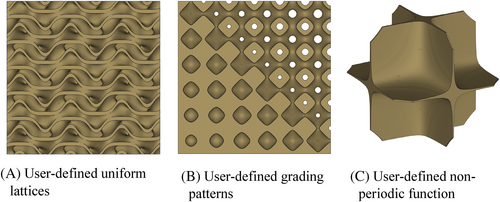
Implicit functions tab can be viewed as the user's gate to generate user-defined level-set functions. In this tab, the user can define the function, the iso-value, the number of cells in the x, y, and z directions and the lattice type (i.e., solid networks or sheet networks). The software will generate the plot and return the relative density of the plotted structure. For example, other level-set equations that are not part of the built-in TPMS structures can be plotted and exported. An example is presented in Figure 4A (see also Figure S5 for numerical values). This tab can also be used to generate functionally graded lattices by controlling the relative density through controlling the iso-value. The user can define the grading function, and it does not necessarily be a linear function. For example, a sample graded in the x and y directions using exponential grading is shown in Figure 4B (see also Figure S5 for numerical values). Also, the user can do hybridization of different lattices such as the hybridization between Gyroid, Diamond, and Primitive lattices as shown in Figure 2E. The detailed mathematical implementation for this three-lattice hybrid structure is detailed in section 3 of the Supporting Information for readers to examine. It worth mentioning that the Implicit function tab is not limited to TPMS structures as it can be used to plot any implicit function that defines a surface of certain topology. For example, plotting the arbitrary function x × y × z = c with sheet-network category yields the nonperiodic structure shown in Figure 4C. This structure resembles a plate-like simple cubic lattice.50
4 3D PRINTING AND COMPUTATIONAL ANALYSIS
TPMS-based lattices are self-supporting structures that do not require any support materials or structures during 3D printing. STL files generated using MSLattice can be uploaded to any 3D printing system and fabricated directly. Examples of metallic 3D printed samples generated using this software are presented in Figure 5. These samples have been printed using the EOS M280 powder bed fusion system available at the core technology platform at the New York University in Abu Dhabi such that 316L powder and the standard EOS parameters have been used.
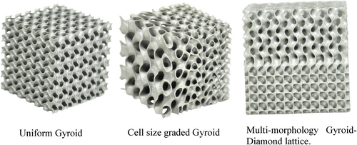
For the purpose of numerical simulations, the user can convert the STL file to a CAD file using the freely available software FreeCAD (https://www.freecadweb.org/). In the Supporting Information, we detail the steps of converting an STL file into a STEP file that can be used in computational modeling using, for example, finite element method or computational fluid dynamics packages.
5 IMPACT OVERVIEW
By making MSLattice freely available for the research and engineering community, it is expected to have a wider adaption of TPMS-based materials in different fields of engineering. Other software packages that can generate TPMS-based materials have been made available.51, 52 However, these packages are very limited in their functionalities and often require the use of third-party software to thicken the generated surfaces of zero thickness. They are also limited in their ability to create solid-network-type structures. The ability to do functional grading is also limited even with the use of a third-party software for thickening. On the other hand, other commercially available tools can be very expensive. MSLattice is a much-advanced software with the capability of generating surface meshes, uniform lattices, and graded lattices. Also, through its implicit function window, the software allows the user to generate any TPMS-based lattice provided that the level-set approximation equation is available. In addition, multimorphology lattices can be obtained through the implicit function window. For this reason, the authors have provided examples in the help menu of the implicit functions tab to support the user.
6 LIMITATIONS
Currently, the software is limited to not being able to lattice an arbitrary CAD shape for the purpose of light-weighting. This is currently achieved by importing the generated unit cell to a third part package such as Magics (Materialise, Belgium) to lattice the structure. Moreover, the software is limited in its ability to grade a structure based on a grayscale image resulting from topology-optimization. In the future, the authors are planning to incorporate such functionalities into this software.
7 CONCLUSIONS AND FUTURE WORK
In this short paper, we present MSLattice, a standalone software written in Matlab for the generation of 3D printable lattices based on TPMS structures. The software allows the user to generate uniform and functionally graded lattices with sheet- or solid-network configurations for a wide range of TPMS topologies. The software also allows the user to export the STL file for the purpose of 3D printing and numerical simulations. In the future, the authors aim to expand this package to allow for lattice-based topology-optimization, as well as the ability to lattice any arbitrary CAD geometry.
ACKNOWLEDGEMENT
The first author would like to acknowledge the help of Juan Esteban Villegas Delgado in certain aspects of coding. The metal 3D printing was performed done using the system available in the Core Technology Platforms at New York University Abu Dhabi.


