Investigation of a new drilling design for loading core specimens with triple holes to determine direct tensile strength values of rock materials
Abstract
Drilled core specimens including a reaming and two loading holes were investigated with both numerical and experimental studies to assess its usability to determine direct tensile strength values of rock materials. A new loading apparatus with rods to insert into the loading holes has been designed and manufactured to supply tension. Elimination of the gluing in the standard direct tensile strength test method is a significant advantage to make both hard and soft rocks possible to be tested. The cylindrical specimens with the diameter of NX size and length to diameter ratio of 3 were used in the tests. In this test method, reaming holes with higher diameter than that of the loading holes were drilled at the middle length of the specimens as the target location for the crack initiation. However, the drilled discs were determined to fail because of the crack initiation at sidewalls of loading holes, instead of the reaming hole. Therefore, loading with inserted rods was not found applicable. The test method and its failure mechanism were discussed for the aim of contributing to relevant studies.
1 INTRODUCTION
The conventional (standard) direct tensile strength (DTS) test for rock materials has an important disadvantage of possible glue part failure instead of that in the rock specimen. As it is known, cylindrical rock cores are glued to steel caps held by the grips of tension equipment in the standard DTS test. The invalid failure of the adhesive part can be seen especially for high strength rock materials in the DTS test. The difficulties associated with the DTS test have enabled researchers to propose alternative methods for evaluation of the tensile strength value. For instance, different DTS test methods like using dog-bone (or dumbbell)–shaped rock specimens have been developed for effective holding. However, the use of dog-bone–shaped specimens are not popular because of its impractical specimen preparation works.1-4
To eliminate the lack of standard (conventional) DTS test, various indirect test methods were also developed. The Brazilian test (or splitting tensile strength test) is the most popular one in the indirect tensile strength (ITS) tests because of its practicality. Although the Brazilian test is applied worldwide, its deficiencies cannot be ignored and have been an important issue to investigate by the community on rock testing.5-8
Because the Brazilian test discs fail under biaxial stress distribution condition, it cannot be used to evaluate the uniaxial tensile strength values of rock materials.9-12 The Brazilian test has another problem resulting from indefinite contact properties like contact angle and frictions, which significantly change the stress distribution in discs depending on deformation characteristics of rock materials. ITS values obtained from the Brazilian test are not only dependent on the strength of the disc specimen material, but also dependent on deformability properties.13-15 Because of the possibility of crack initiation in the compression zone beneath the contact points of the loading jaw, determination of the ITS values of rock materials under the diametric compression is disadvantageous.16-18
Various reasons as written above indicate the importance of direct tensile strength (DTS) test methods. In this study, a new direct tensile strength test method of using drilled core specimens was investigated by numerical and experimental analyses. Core specimens with triple drill holes consisting of two for loading and a middle reaming one were used in a new DTS test method investigated within this study. The motivation for carrying out this study is having an ability to determine DTS values of rock materials by using no adhesive, which is the cause of limitations in the load levels for rock failure. Using no adhesive to hold and load specimens was assessed to be a significant advantage.
To supply tension, steel rods were inserted into the up and downside loading holes of specimens and pushed by a new loading tool designed and manufactured as seen in Figure 1. The devices of the new tool displaced in oppose to the press movement. As the compression of the press continues, the tensile stress supplied by the new equipment increases until the failure. The reaming hole was designed to have a higher diameter in comparison with the loading holes for the aim of making failure at the sidewalls of it. In a previous study by Komurlu and Demir, usability of rock cores with the drilled reaming hole was investigated and assessed to be an acceptable way to supply rock failure under the control of uniaxial stress concentration.19 The sidewalls of the reaming holes were determined to be the location of the start of cracking under direct tension test. Within the previous study on testing rock cores with the reaming hole, specimens were glued as similar with the standard DTS test method. As same with the previous study, it was aimed to make failure because of the practically uniaxial tensile stress concentration at sidewalls of the reaming holes. Novelty of this study is loading specimens by the rods inserted into the holes instead of gluing both ends of the cores.

In this study, the failure mechanism of drilled core specimens with triple holes were investigated to assess whether the new tool and loading design can be used to determine the uniaxial tensile strength values of rock materials. The ideal failure shape for a valid test, stress distribution in critical locations for the crack initiation were investigated carrying out three-dimensional numerical analyses. Additionally, an experimental study was carried out for controlling results obtained from the numerical analyses.
2 METHODOLOGY
2.1 Numerical study
To better understand the stress distributions around drill holes, finite element analyses (FEA) were performed by using the ANSYS software, which contains special elements and material models for brittle materials like rocks. In the numerical study, failure of the models was investigated to assess whether it is valid under the control of the uniaxial tensile stress concentration.
As parallel to the suggestions of the International Society for Rock Mechanics and Rock Engineering (ISRM), the core models were modeled to have the diameter of NX size (54 mm) and length to a diameter ratio of 3.20 Material properties as input values for the rock models are given in Table 1. Different materials were modeled in the analyses to investigate whether the hole drilling design has a same effect in case of having different material properties like Poisson's ratio and modulus of elasticity.
| Material Model | UCS, MPa | UTS, MPa | E, GPa | v |
|---|---|---|---|---|
| Material 1 | 60 | 6 | 30 | 0.3 |
| Material 2 | 60 | 6 | 45 | 0.3 |
| Material 3 | 60 | 6 | 15 | 0.3 |
| Material 4 | 60 | 6 | 30 | 0.4 |
| Material 5 | 60 | 6 | 30 | 0.2 |
- Note. UCS, uniaxial compressive strength; UTS, uniaxial tensile strength; E, modulus of elasticity; v: Poisson's ratio
Material of the loading apparatus was modeled with Solid185 as rigid steel with 350 GPa modulus of elasticity. The contact surfaces between the rock and loading rods were simulated with the Conta174 and Targe170 contact pairs. Different coefficient of friction values of 0.3 and 0.6 were used to investigate the effect of the friction between rock and steel of the loading apparatus on the results of the analyses.
Considering the limitations for the drill process practicality and having big enough size to make the crack initiation at its wall, reaming hole diameter was chosen to be 18 mm within both numerical and experimental studies, which is two times higher than the diameter of the rod inserted in the loading holes. In case of relatively small loading hole diameters, rod dimensions are not sufficient to supply enough load bearing capacity for the rock specimen failure. Additional numerical models with a loading hole diameter of 5 mm were analysed to investigate whether relatively small loading holes can be used or not. The rods were modeled to have the same diameter with that of the loading holes in the numerical analyses.
Eight-node solid brick elements (Solid65) were used for three-dimensional modeling of rocks, which have the capability of cracking in tension, crushing in compression, plastic deformation, and three degrees of freedom at each node, including transition in the nodal x, y, and z directions. It is stated in the ANSYS software manuals that the Solid 65 elements are usable to simulate failure in brittle geological materials such as rocks. More details about Solid65 can be found in section 14.65 of the ANSYS theory reference.21
Materials were modeled by considering the linear and nonlinear properties defining the behaviors of the elements. The modeled materials were defined as linear elastic material until the crack initiation occurs. After the crack initiation, change in the normal and shear stresses has been recalculated by the program. The recalculated shear stresses were transferred by the plasticity because of the generated open and closed cracks. The shear transfer coefficient was accepted as 0.3 and 0.1 for closed and open cracks, respectively. In addition, the stiffness reduction factor considered as 0.6 to define plasticity had an important role in the behavior of cracked elements. These models predicted the failure of brittle materials according to the Willam-Warnke failure criteria used for concrete, rocks, and other cohesive-frictional materials such as ceramics.22
A static analysis was performed for each of the models, and the full Newton-Raphson method was used for nonlinear analysis. For displacement-controlled loading, displacements were divided into multiple sub steps until the total displacement was achieved. Stress distributions and cracking mechanisms for all specimen models were plotted for comparison with the experimental results.
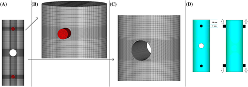
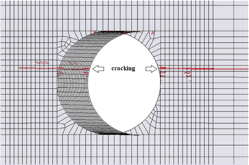
The mesh length in the rock models was chosen to be 0.5 mm around drill holes where the most critical part for the start of failure is, and increase from 0.5 mm depends on the distance from the hole. The maximum mesh size was 2 mm in the numerical analyses. Various finite element models with different meshes were analyzed in an effort to ensure that the selected mesh is dense enough to provide sufficient solution convergence. A figure for the meshing condition is given in Figure 2. In this numerical study, the tensile strength test was simulated applying load from rods inserted into the up and down side parallel loading holes in the opposite directions.
2.2 Experimental study
To check findings from the numerical study, a series of tensile strength tests were performed by using homogeneous and isotropic rocklike materials in this study. The failure shapes and crack locations of tensile strength test specimens were compared with those obtained from the numerical method. Specimens were inserted into the steel stands having holes. Then, the rods were inserted into the loading holes and mounted on the stands. The upside and downside rods were, respectively, moved upward and downward as the hydraulic press pushes the stands in the opposite directions.
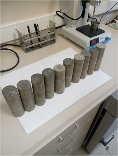
To make a homogeneous and isotropic rocklike material, only Cem I type ordinary Portland cement and tap water were used. The mix had the ratio of water to cement of 0.5 by weight. The mix was homogenized in a concrete mixer for 10 minutes. Then, the specimens were casted into NX size diameter molds with the bottom allowing the bleed water drainage, compacted using tamping rods, and were placed on the vibration table to remove air in fresh mix. The specimens were casted into the molds with the ratio of length to diameter of 3 in two steps for making them well compacted and removing air in the mix properly by using tamping rods after each casting steps. In total, 10 specimens were casted (Figure 3).
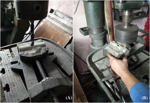
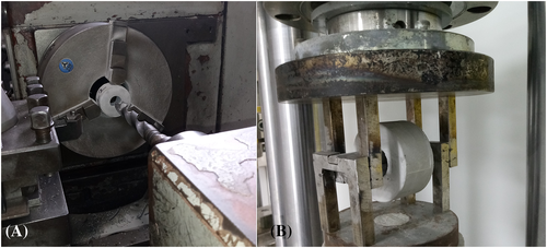
Two days after the casting process, specimens were drilled by a stand driller, using the bit diameters of 9 mm for the loading holes and 18 mm for the reaming holes (Figure 4). The reaming holes were drilled at the middle length of core specimens. After the drilling process, distance between the wall of the loading holes and the end of the cylindrical specimens was 18 mm (Figure 2D). Drilling design and hole locations were same in the experimental and numerical analyses. As seen in Figure 4, the holes were vertically drilled through the diameter of the circular cross-sections of specimens. The loading and reaming holes were drilled as parallel with the same direction. For the ability of insertion into the holes, steel rods used for loading specimens have the diameter of 8.5 mm, which is slightly lower than that of the bit used to drill the loading holes. The loading rate was chosen to be 0.2 kN/sec.
3 RESULTS
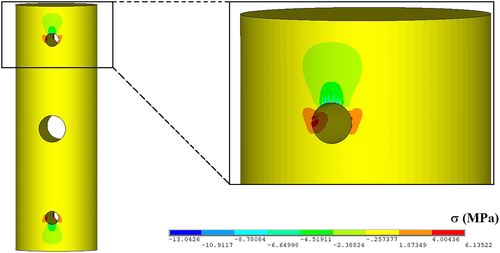
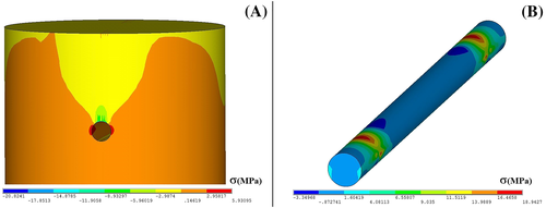
According to the results obtained from the numerical analyses, maximum tensile stresses were determined to be induced at the sidewalls of the loading holes (Figure 5). Therefore, cracks occurred at the sidewalls of the loading holes in the failed specimen models (Figure 6). For all the material models, specimens were failed as the stresses at the sidewalls reach to be quite close to the uniaxial tensile strength value of 6 MPa.
The maximum compressive stresses were determined to induce at the contact surfaces of the loading holes and rods. The maximum compressive stress values at the contact were, respectively, about two and three times those of the maximum tensile stresses induced at the sidewalls of the loading holes with diameters of 9 and 5 mm. Because the compressive strength values of the rock materials are much higher than their tensile strength values, the crack initiation of the drilled core specimen models occurred because of the tensile stress concentration at the sidewalls. With a decrease in the loading hole diameter, tensile stress concentration at the sidewalls of the reaming holes was found to not vary significantly. Therefore, small loading hole diameters were assessed to be not advantageous in terms of having a desired failure initiated at the reaming hole sidewalls. Because the tensile stress concentrations at the sidewalls of the loading holes were much higher than those of the reaming holes, the loading hole diameter was determined to be not an effective parameter for changing the crack initiation location for different cases of drilling designs. Although stresses induced in the steel rod increased with decreasing loading hole diameter, the stress concentration was not high enough to make steel failure as seen in Figure 7.
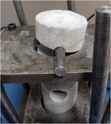
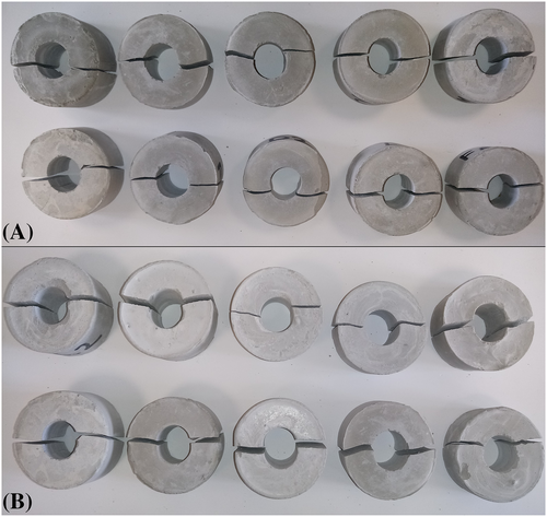
Similar to the observations from numerical analyses, failure of drilled specimens initiated at the sidewalls of the loading holes, which are the location for the maximum tensile stress induced. Specimens were cracked through the sidewalls of the loading holes in the experimental study (Figure 8). Therefore, it can be noted that the experimental study verified the numerical analyses in terms of mechanism of the failure resulting from the tensile strength concentration at the sidewalls of the loading hole. According to the results of both numerical and experimental studies, the aim of the reaming hole could not be achieved. It was understood that there was no need to drill reaming holes. Because the stress concentration at the sidewalls of the loading hole is much higher in comparison with the reaming holes, the holding mechanism of rod insertion was found not a convenient way.
4 DISCUSSIONS AND CONCLUSION
The DDT test specimens were found to be able to prepare by an easy drilling work. It should be noted herein that the hole with the diameter of 18 mm was practical to be made in one step drilling. In case of preparing hard and brittle rocks, more than one drilling steps with increasing bit diameters can be applied to prevent rock cracking while the specimen preparation step. For prevention of damaging during the specimen preparation, the drilling process should be done carefully and proper equipment like drilling tools should be used. On this topic, new studies will guide for development of the specimen preparation details.
Since stress distribution in the drilled disc specimens can vary with the change of geometry and size parameters, the findings of this study should be considered for the relevant case.23-25 The tensile stress values at the sidewalls were found to vary along drill holes. As seen in Figure 5, the maximum tensile stresses were determined to be induced near the outside of the holes, where the critical location for the start of cracking is.
The adhesive failure problem in DTS testing is eliminated by using the new tensile strength evaluation method of testing drilled cores with triple holes. However, the reaming hole was not found usable with the loading rods inserted because the loading holes were determined to be the location of failure initiation. By increasing the diameter of the reaming hole, stress concentrations at its sidewall can increase. However, it seems that only extremely large reaming holes which are impractical to drill can supply a failure initiated form its walls.
Because the diameter of the reaming hole is much bigger than that of the loading holes, the crack initiation was estimated to be at the sidewalls of the reaming holes. However, the loading holes were cracked as an unpredicted finding. This outcome of the study is expected to contribute to other relevant studies by discouraging the use of loading holes. Because stress concentrations decrease with increasing the distance from the load source, a possible reason for the failure at the loading holes is being near by the rod contact.
Compressive strength values of rock materials are generally eight or more times higher than their tensile strength values.26-28 The compressive stresses at the contact of the loading hole and rods were found to be not high enough to cause a compressive failure. Specimens were cracked because of the tensile stress concentration at the sidewalls. According to the stress distribution analyses, it is easy to designate the compressive failure from the location of cracking. As checked by the tests, crack propagation because of the tensile stress concentration is perpendicular to the loading direction.
In case of using a method with a failure of the loading hole, the drilled disc tension (DDT) test method can be used because it is more practical than the method tested within this study. In the DDT test, only one loading hole with a diameter of 20 mm is drilled through the Brazilian discs with the diameter of NX core size to insert rods of its loading apparatus as seen in Figure 9. The contact angle between the loading rods and the drill hole is 50°. For the relevant case of the DDT test, tensile strength value calculation is formulated with an equation suggested in accordance with the numerical and experimental analyses. Specimens loaded in the DDT test failed because of the crack initiation under the condition of uniaxial tensile stress distribution at the sidewalls of the hole (Figure 10). More details on the DDT test can be found in the paper written by Komurlu and Demir.29
A new testing method of using specimens with triple drills was investigated to assess whether it is able to contribute to the rock testing area or not. According to the results obtained from this study, the specimens with triple holes are not usable to make crack initiation at the reaming hole wall. This study aims to be a reference for other relevant studies and to suggest for using no reaming holes with the loading holes. Because the reaming holes are not cracked, it is not necessary to drill them. On the other hand, the holding mechanism with the rod insertion cannot be assessed as convenient because of crack initiation at the loading holes. The aim of the reaming hole was the prevention of loading hole failure and making a crack initiation location at its sidewalls. If specimens cracked at the reaming hole location, a formulation would be investigated and suggested for tensile strength value calculations considering the failure load for a relevant specimen size and geometry properties. However, the use of core specimens with the triple holes were assessed to be not usable for the determination of tensile strength values of rock materials. This outcome is believed to be notable for the aim of contributing further analyses.
CONFLICT OF INTEREST
The authors wish to confirm that there are no known conflicts of interest associated with this publication and there has been no significant financial support for this work that could have influenced its outcome.


