Modifications to Implanting the OSIA® 2 Bone Conduction Hearing Implant: How I Do it
Editor's Note: This Manuscript was accepted for publication on April 16, 2022
Internal departmental funding was utilized without commercial sponsorship or support. This was an investigator-initiated study. CLWD is a consultant for Advanced Bionics Corp., Cochlear Corp., and Envoy Medical. JTR and MLC are consultants for Cochlear Americas and receive research grant money. DJ is a consultant for Cochlear Americas and has received research grant money from Advanced Bionics Corp.
The authors have no other funding, financial relationships, or conflicts of interest to disclose.
Graphical Abstract
INTRODUCTION
The Cochlear OSIA® 2 System is the latest generation osseointegrated implant by Cochlear Corporation (Cochlear Americas, Englewood, CO). Indications include patients with conductive or mixed hearing loss with a bone conduction pure tone average of ≤55 dB HL or patients with single-sided deafness with normal hearing (i.e., ≤20 dB HL pure tone average) in the contralateral ear. The OSIA system is comprised of the OSI200 implant and the BI300 implant (Fig. 1). The OSI200 implant includes a coil and a removable magnet in its top half, and the actuator with fixation screw thread in its bottom half. They are connected by a thinner, flexible section known as the “waist” of the device. The OSI200 fixates to the titanium BI300 implant.
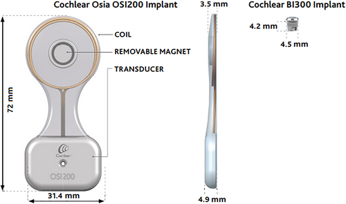
The transcutaneous design of the OSIA allows for fewer skin complications commonly observed with the BAHA Connect and Attract.1 Its piezoelectric transducer is fully implanted which avoids signal attenuation due to skin and avoids the need for a large, strong magnet to retain the external device, both of which were limitations of the older transcutaneous BAHA Attract system.
Though complications for the OSIA procedure are low, potential issues include wound breakdown, infection, hematoma, dural injury, or difficulty with magnet retention.2, 3 The authors present their experience with implanting the OSIA 2 system and discuss modifications that are made in certain situations to further reduce these potential complications and simplify surgical placement.
METHODS
Institutional review board approval was obtained, and a retrospective review was performed from December 2019 to December 2021 of patients who underwent Cochlear™ Osia® System 2 using a modified technique.
SURGICAL TECHNIQUE
Planning Device Placement
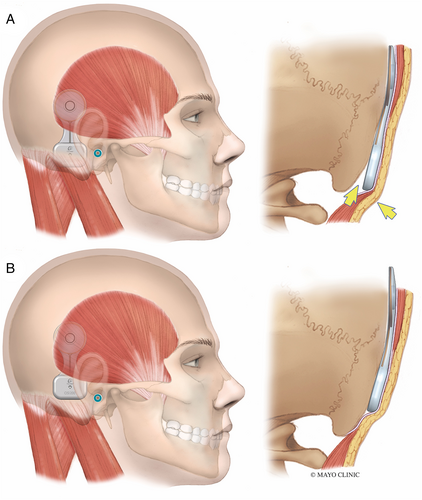
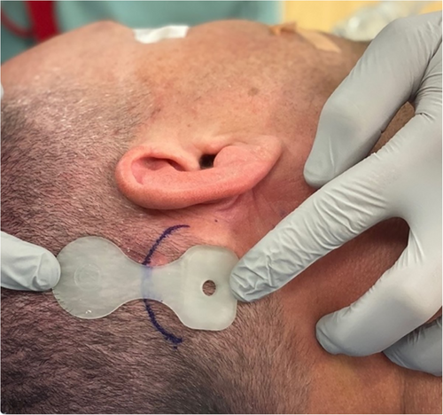
Before prepping and draping the patient, the OSI200 Implant template is positioned on the skin to plan optimal placement. A flat part of the skull is ideal for the actuator. The manufacturer recommends placing the implant position in a horizontal line with the external auditory meatus. However, we have found that this often causes the inferior portion of the actuator to cantilever off the skull slightly as the mastoid bone curves medially (Fig. 2A). This can result in significant skin tension at the inferior edge of the actuator. It also causes the device to appear more prominent and less cosmetic. Placing the device more superior so the screw fixation site is 1–2 cm above the level of the external auditory meatus can prevent the skin from tenting over the device at its inferior edge (Fig. 2B). Placing it more superiorly also reduces the need to dissect the nuchal muscles which can lead to unnecessary bleeding from emissaries, hematoma formation, and postoperative pain.
The skin thickness at the site of the magnet is measured. A maximum skin flap thickness of 9 mm over the coil is required for good magnet retention. A thicker skin flap may necessitate skin thinning or, alternatively, placing the top portion of the device lateral to the temporalis muscle (a modification that is described below).
Incision planning should take into consideration prior ear surgery. The presence of a mastoid cavity may necessitate placing the incision more posteriorly. When possible, incorporating a portion of the old incision into the new incision is preferable to creating a separate but close parallel incision or creating an acute angle of intersection with the prior incision.
Incision Modification
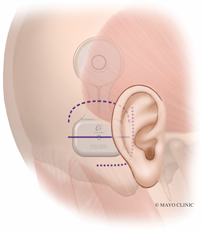
The J-incision as recommended by the manufacturer can sometimes lead to significant skin tension, particularly along the anterior-inferior corner of the device, particularly if the device is placed too inferior (Fig. 3, dotted line). The actuator is rigid and has a thickness of 4.9 mm. The curve of the J-incision can come very close to the point of maximal skin tension at the anterior-inferior part of the actuator, increasing the risk of wound breakdown and device exposure. An incision that is 10–15 mm away from the device may mitigate this, but this results in a much larger, more visible scar that extends more inferiorly and requires exposure and elevation of the nuchal musculature.
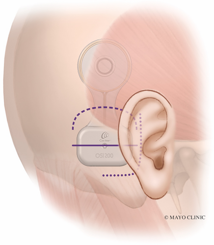
Two alternative incisions used by the authors are described here to avoid placing the incision at the site of wound tension. The first is a linear incision horizontally placed over the intended site of the implant screw (Fig. 3, solid line). Video S1 illustrates this technique. The incision is carried down to the bone. This provides direct access to the bone for appropriate screw placement, which should be perpendicular to the cortex. Superior and inferior tissue flaps are undermined, which aid in closing the wound without tension (Fig. 4). This is in contrast to the J-incision whereby undermining the anterior skin flap is limited by the postauricular sulcus and therefore that skin cannot be recruited to close the incision under less tension. The site of magnet coupling is at the top of the device, which is away from the incision. This removes the theoretical risk of incision breakdown due to ischemia from the magnet.
Describing surgical modifications for a new transcutaneous active-drive bone conduction implant, the Cochlear OSIA.
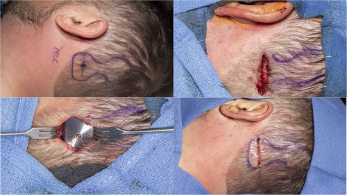
The second incision alternative is the inverted-U incision that comes across the “waist” of the device (Fig. 3, dashed line and Fig. 5). This creates an inferiorly-based skin and muscle flap. This provides wider access and exposure to the mastoid or occipital bone. This may be advantageous in patients, where polishing the bone with a drill is helpful to ensure a flat surface and even contour with the device. Similar to the linear incision, the superior and inferior skin may be widely undermined. Upon closure, there is less skin tension across the device since the “waist” of the device is thinner as opposed to the thicker actuator portion.
Coil Pocket Modification
In most cases, a subperiosteal pocket is developed that extends deep to the temporalis muscle for placement of the coil. However, in patients with greater than 9 mm scalp thickness, a modification involves developing a plane lateral to the temporalis fascia. This modification potentially mitigates the need to thin the skin, which is difficult to access without making a much larger incision that extends superiorly. The “waist” of the device is flexible and made of silastic which allows it to easily bend as the device transitions from a plane above the muscle to the subperiosteal plane where the actuator is fixed.
Implant Placement
If the bone is uneven, a large diamond bur with irrigation is used to flatten the bone. In some patients with thin skin, a shallow well can be drilled to recess the device lower into the bone. The BI300 screw is placed in the usual fashion. It is important that the drill is perpendicular to the bone to avoid the actuator sitting unevenly and tilted with respect to the bone, which can lead to wound complications due to excessive skin tension. The bone bed indicator is used to check for clearance around the bone and a drill is used to remove any obstructing bone. The coil end of the device is then placed into its pre-developed pocket and the actuator portion is fixated to the BI300 implant with a screw and hand tightened with 25-Ncm of torque.
Closure
The musculo-periosteal layer can be tight due to the thickness of the device. Hand-tied 2–0 vicryl suture is helpful in reapproximating this layer such that the more superficial layers are under less tension. The deep dermal layer and skin are closed in the usual fashion. A mastoid dressing is applied.
RESULTS
A total of 25 OSIA's using one of the modified incisions described here have been placed by the six surgeons in this study (N.L.D., M.L.C., D.R.F., C.L.W.D., J.T.R., D.J.). There have been no surgical complications or postoperative wound complications with using the linear (n = 12) or inverted-U (n = 13) modified incision.
DISCUSSION
The aim of these modifications is to avoid wound complications, improve sound processor coupling with the magnet, and improve aesthetics. Several modifications to the procedure are discussed here. The choice of which modifications to employ is made on a patient-specific basis. Surgical decision making is influenced by the thickness of the skin (both at the coil site as well as in the postauricular area), the surface area of the mastoid cortex, the thickness of the bony cortex, and prior incisions in those with a history of ear or lateral skull base surgery.
Placing the device such that the inferior edge of the actuator does not extend inferiorly off the mastoid can reduce tension across the skin during closure and provide an aesthetic benefit by having a less visible bump. The smaller incisions described here are aimed at reducing dissection of the nuchal muscles at the mastoid tip, which expedites healing time, decreases hematoma formation, and minimizes postoperative pain. With these modified incisions, the superior and inferior flaps can be widely undermined, thereby allowing the incision to come together under less tension. With the vertically oriented J-incision, there is not a significant amount of anterior skin to recruit because the incision is made near the postauricular sulcus. As a result, the posterior skin flap is under more tension as it is pulled anteriorly during closure. Avoiding an incision along the anterior-inferior aspect of the device (as is the case with the J-incision), may reduce wound breakdown or pressure points in that area, which tends to be the site of greatest skin tension.
Although traditional surgical dogma is to never place an incision over a device, in the authors' experience with implanting this device as well as other devices, such incisions can be safely executed without complications, especially when there is meticulous attention to wound closure. Furthermore, the pressure exerted by the magnet is not under the incision, thereby mitigating the risk of breakdown. Long-term follow-up is warranted to further assess if there are any significant differences between the different approaches.


