Soil nitrogen dynamics after slurry injection in field trials: Evaluation of a soil sampling strategy
Abstract
Slurry injection below maize seeds is a rather new application technique developed to improve the nitrogen use efficiency of liquid organic manure. To enable the characterization of the spatial and temporal soil mineral nitrogen (SMN) dynamics after slurry injection, the present study aims to develop an appropriate soil sampling strategy. Three consecutive experiments were conducted. The first testing of the soil sampling approach was conducted in an existing field trial where the slurry was injected down to a depth of 12 cm (upper rim) below the soil surface. The soil profile (75 cm wide) centered below the maize row was sampled grid-like to a depth of 90 cm. Around the injection zone, soil monoliths (SM) were sampled using a purpose-built soil shovel. Below the SMs and in the interrow space (15 and 30 cm distance to the row) a standardized auger procedure was performed. The second experiment aimed at improving the sampling strategy with a focus on sample homogenization quality and necessary sample sizes per pooled sample. Furthermore, the risk of a carryover of slurry components along the soil core due to drilling an auger through a slurry band was analyzed. In the third experiment this improved sampling strategy was validated. Results from the first testing of the sampling procedure showed that the strategy is suitable, although some problems occurred (especially the high spread in values among the replications causing high coefficients of variation (CV) of mostly 40–60%). The improvement trial revealed that due to the high gradient of SMN concentration in the direct range of the injection zone an intensive homogenization of these samples is required. Suitable sample sizes (twelve auger samples and six soil monolith samples per pooled sample) have to be collected to obtain reliable SMN values. Drilling an auger through a slurry band to sample subjacent soil layers has to be avoided. Following this enhanced sampling strategy, in the final validation trial the spread in values were considerably reduced and resulted in CV values of mostly < 20%. The developed sampling strategy enables the characterization of the spatial and temporal SMN dynamics when slurry has been band-injected below a maize row. The method can be transferred to other row crops and different slurry injection spacing.
1 Introduction
Slurry injection has become an increasingly common fertilization method for maize because it had been shown that the traditional broadcast surface application of slurry causes problems such as ammonia volatilization (Misselbrook et al., 2002; Carozzia et al., 2013) or surface runoff (Smith et al., 2001; Ceretta et al., 2010). Several studies revealed that slurry injection close to the maize row leads to enhanced nitrogen use efficiency (Sutton et al., 1982; Schmitt et al., 1995; Ahmed et al., 2012; Schröder et al., 2015). However, improved understanding of the soil mineral nitrogen (SMN) dynamics when using slurry injection techniques is essential (Dell et al., 2011).
The main challenge for soil sampling after banding fertilizer are the huge differences in nutrient concentrations around the injection zone compared to the unfertilized soil zone. Standardized random sampling strategies are not suitable for the characterization of the soil nutrient status (Kitchen et al., 1990; Van Vuuren et al., 2000; Tewolde et al., 2013). For a reliable description of the soil nutrient status after harvest, Kitchen et al. (1990; extractable P) and Tewolde et al. (2013; total C, total N, and extractable P, K, Mg, Cu, Mn, Fe, and Zn) recommended to take auger samples in a defined volume ratio from directly above the fertilizer band and perpendicular to the band towards the unfertilized interspace. Similar approaches were used to characterize the spatial and temporal SMN dynamics after urea ammonium nitrate injection (Clay et al., 1995) or slurry injection (Assefa and Chen, 2007). However, when using an auger, it is not possible to take samples accurately in the direct surrounding of the fertilizer band, because it is not feasible to locate the band precisely from above the soil surface.
Therefore, in other studies soil pits perpendicular to the fertilizer bands were trenched to an enable very small-scale grid-like sampling in the direct range of the injection zone as well as (at least partially) in the unfertilized interspace (McCormick et al., 1983; Comfort et al., 1988; Petersen et al., 2003). Van Vuuren et al. (2000) used a metal sampler with 4 cm × 4 cm grids for sampling to a depth of 28 cm and concluded that this method is not practicable for extensive studies. Comfort et al. (1988) conducted a slurry-injection field trial without crops and used a backhoe to excavate an ≈ 1 m deep trench perpendicular to the slurry-injection bands, and sampled the soil profile in a grid-like 5 cm × 5 cm to a depth of 90 cm. However, this procedure is not practical for ongoing field trials. Sawyer et al. (1990) conducted maize field trials with injected beef slurry over 4 years. In the first 3 years they used different auger sampling methods [comparable to Clay et al. (1995) and Assefa and Chen (2007)] to characterize the SMN dynamics. In the last year, they located the injection zone precisely by digging a trench across the application area and used plastic vials for sampling directly the injection zone disregarding the unfertilized interspace. But finally, no practicable soil sampling strategy was suggested.
Zebarth et al. (1999) determined the spatial and temporal SMN dynamics in a maize field receiving a mineral nitrogen fertilizer band as side dress. They collected the complete soil material in a trench 40 cm long (perpendicular to the maize row), 10 cm wide, and 30 cm deep, and segmented it into 5 cm × 10 cm × 15 cm soil monoliths. For the 30–60 cm soil layer a standardized auger sampling procedure was used. This very high sampling effort was only performed in one field trial to deduce a soil sampling strategy for estimating the SMN status in the root zone for fertilizing recommendations at a given date.
Based on these findings, the objective of this study was to develop and evaluate a practicable soil sampling strategy to enable a reliable characterization of the spatial and temporal SMN dynamics in field trials fertilized with slurry band-injection below the maize row. Transformations of SMN in the direct range of the injection zone, SMN distribution in the unfertilized interrow space, and the sampling depth down to 90 cm were considered.
2 Material and methods
2.1 Experimental sites, soil conditions, and slurry properties
Three consecutive experiments were conducted at different sites in Lower Saxony, northwest Germany in 2013 and 2014 (Table 1). A first testing of the sampling procedure (further on called “test trial”) was conducted at the Wehnen site (Table 1) in 2013. This field trial was part of a study in which a new technology for slurry band-injection was evaluated for maize fertilization and one of the eleven treatments was selected to test the soil sampling strategy. Based on these results, a so-called “improvement trial” was conducted to enhance the sampling method at the Lechtingen site (Table 1) in autumn 2013. To implement and verify the findings, a “validation trial” was performed at the site in Hollage in 2014 (Table 1). This latter one was also executed in one of six treatments in an ongoing maize trial.
| Site characteristics | Soil properties | Slurry properties | |||||||||||
|---|---|---|---|---|---|---|---|---|---|---|---|---|---|
| Site | Coordinates | Altitude | Sand | Silt | Clay | Soil texture |

|
Soil type (IUSS Working Group WRB, 2014) | Dry mass (DM) | N | NH4-N | ||
| N | E | / m asla | / % | / % | / g kg−1 | / g kg−1 | |||||||
| Test trial | Wehnen | 53°11′ | 8°08′ | 9 | 88 | 9 | 3 | sand | 5.4 | Gleyic Podzol | 3.0 | 3.7 | 2.6 |
| Improvement trial | Lechtingen | 52°20′ | 8°01′ | 87 | 96 | 2 | 2 | sand | 6.1 | Gleysol | 7.9 | 6.8 | 4.2 |
| Validation trial | Hollage | 52°20′ | 7°58′ | 65 | 91 | 8 | 1 | sand | 5.3 | Plaggic Podzol | 9.3 | 7.2 | 5.5 |
- aasl = above sea level.
Long-term average annual air temperature was ≈ 9.5°C and average annual precipitation ≈ 850 mm. The soil textural class of the topsoil was sand at all sites. According to IUSS Working Group WRB (2014) the soil type in Wehnen is a Gleyic Podzol, in Lechtingen a Gleysol, and in Hollage a Plaggic Podzol (Table 1). Pig slurries from regional pig fattening farms were used in the three experiments (Table 1). Dry mass of slurries ranged from 3.0 to 9.3% and the total nitrogen from 3.7 to 7.2 g kg−1. The dry matter content was analyzed gravimetrically by oven-drying at 105°C to constant weight. Total N concentration in the slurries was determined using the Kjeldahl method after nitrate reduction with Devarda's alloy (DIN EN 15476:2009-04, 2009), while the ammonium concentration was determined with titration after direct distillation of the slurry with magnesium oxide (according to Bremner and Keeney, 1966).
2.2 Soil sampling and experimental set-up
2.2.1 Soil sampling method
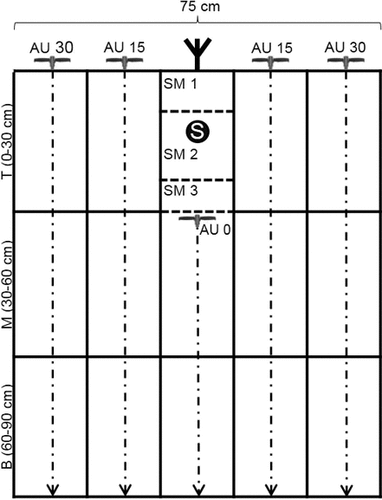
The intent of the sampling strategy was to sample the soil profile grid-like to a soil depth of 90 cm (Fig. 1). That was accomplished by combining a standardized auger (1.8 cm inside diameter) procedure with a purpose-built metal shovel (15 cm wide, 15 cm high and 10 cm deep; Fig. 2). Using this sampling shovel yields rectangular soil monoliths (SM).
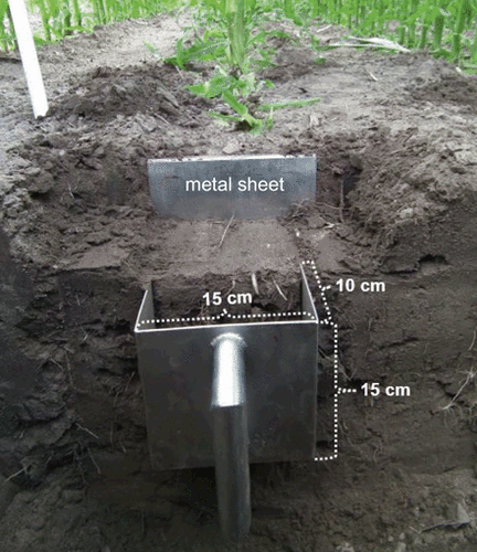
Usage of the soil shovel to obtain the soil-monolith sample around the banded slurry (SM 2); metal sheet = used to limit the SM in front.
In the interrow space, samples were taken with an auger at a distance of 15 cm and 30 cm perpendicular to the rows [auger (AU) 15 / 30; Fig. 1]. Respective samples from the left and the right side of a maize row were pooled. Each sample was divided into three layers termed top (T; 0–30 cm), middle (M; 30–60 cm), and bottom (B; 60–90 cm). Samples underneath the row were taken using the metal shovel and an auger. For this purpose a small pit was dug (about 35–45 cm deep) to ensure a precise localization of the banded slurry. After that a metal sheet was hammered into the ground in front of the shovel (Fig. 2). At first one monolith was taken from above the injected slurry (SM 1). Then a second soil monolith (SM 2), which contains the complete slurry band (S), was sampled (Fig. 2), and finally a third one was taken from the area directly below the slurry band (SM 3). For sampling the two layers underneath SM 3 again an auger was used up to a depth of 90 cm (AU 0).
2.2.2 Testing the sampling approach
The field trial at the Wehnen site, used for the first testing of the procedure, had eleven treatments in a randomized complete block design with four replications. Previous crop was winter triticale and the field was plowed in spring 2013. Each experimental plot was 3 m wide, 15 m long and included four maize rows with a row-spacing of 75 cm. In the treatment selected for our soil sampling experiment, the slurry (Table 1) was applied with a four-row slurry injector (XTill, Hugo Vogelsang Maschinenbau GmbH, Essen/Oldenburg, Germany) at a row-spacing of 75 cm on May 07, 2013. The application rate was 48 m3 ha−1. The slurry band was ≈ 6 cm wide and ≈ 8 cm high, and its upper rim was about 12 cm below the soil surface. Sowing of maize was carried out at a drilling depth of 5 cm and a sowing rate of 9.0 grains per m2 on May 10, 2013. The maize seed (variety: LG 30222, Limagrain GmbH, Edemissen, Germany) was placed vertically above the slurry bands.
Soil samples were collected post emergence [May 30, 2013; 23 days after injection (DAI)] and at the ten-leaf developmental stage (July 10, 2013; 64 DAI). The soil samples were taken, as described in Fig. 1, from one of the middle rows per plot in order to avoid edge effects. One auger on the left and one on the right side of the row were collected for each interrow location (AU 15 and AU 30). The two auger samples per location were pooled for each soil layer (top, middle, and bottom, respectively). Soil monoliths were taken at depths of 0–10 cm (SM 1), 10–25 cm (SM 2), and 25–40 cm (SM 3) in the same row as the augers. One monolith was sampled per depth. To obtain the samples for AU 0, two augers per plot were pooled. On the first sampling date these augers (AU 0) were drilled directly through the banded slurry. At the second sampling date they were drilled into the planar of the third soil monolith after sampling SM 1–3 and, thus, did not get into contact with the slurry band. All soil samples were collected in buckets and then homogenized intensively by hand and using a 5-mm sieve. Afterwards, 200 (AU) to 300 (SM) g of soil were packed into plastic bags and immediately frozen until analyzed.
2.2.3 Improving the sampling strategy
After harvesting grain maize, a single slurry band was injected with a purpose-built single-row injector at the Lechtingen site on November 29, 2013. The application rate of the pig slurry (Table 1) was 25 m3 ha−1. The slurry band was 16 m long, ≈ 5 cm wide, ≈ 7 cm high, and its upper rim was about 17 cm below the soil surface.
Soil sampling was carried out 5 DAI (December 4, 2013) but only to a depth of 60 cm (top and middle soil layers; Fig. 1). To obtain sufficient soil material for analysis, soil from two auger samplings close to each other were pooled. This procedure resulted in about 200–220 g of soil per sample. In total, 64 auger samples were collected in the interrow space (left and right side of the slurry band). They were distributed evenly along the 16 m long slurry band. In addition, 48 auger samples were taken from a position perpendicular through the slurry band to a depth of 60 cm. Furthermore, soil monoliths (SM 1–3; Fig. 1) were collected at eight positions at depths of 0–10 cm (SM 1), 10–25 cm (SM 2), and 25–30 cm (SM 3). To sample the 30–60 cm layer underneath the eight soil monolith positions (AU; Fig. 1), an auger was used. The 48 auger samples and eight soil monolith positions were also distributed evenly along the 16 m slurry band.
The further processing of all soil samples was carried out as described for the test trial. However, the total amount of soil from the monolith samples was split into subsamples. This resulted in six subsamples for SM 1, ten subsamples for SM 2, and five subsamples for SM 3. Each subsample contained ≈ 250–350 g of soil. This was done to test the quality of the homogenization.
2.2.4 Validating the sampling approach
The field trial at the Hollage site with six treatments had a randomized complete block design and four replications. Previous crop of this maize trial was silage maize and the stubble cultivation was performed twice (March 05 and 27, 2014) with a disc harrow (working depth ≈ 10 cm). One experimental unit was a plot 3 m × 24 m long with four maize rows with a spacing of 75 cm. For the selected treatment, the pig slurry (Table 1) was applied with the same slurry injector as used in the test trial at an application rate of 23 m3 ha−1 on April 11, 2014. The slurry band was placed 12 cm (upper rim) below the soil surface. Maize (Zea mays L. cv. Ricardinio, KWS SAAT AG, Einbeck, Germany) was sown on April 25, 2014 (drilling depth: 4.5 cm, sowing rate: 9.2 grains m−2) .
Soil samples were collected before emergence (May 05, 2014; 24 DAI) and at the ten-leaf developmental stage (July 11, 2014; 81 DAI) in the two middle rows per plot as described in Fig. 1. The soil of twelve single auger samples per interrow location (AU 15 and AU 30) was combined into a pooled sample per plot. The locations of the twelve augers were distributed evenly on the left and right side of the two middle maize rows over a row length of ≈ 0.5 m using a template. The samples were collected in three buckets (top, middle, and bottom, respectively) per interrow location (AU 15 and AU 30), thus, six buckets per plot. The soil monoliths (Fig. 1) were taken at depths of 0–8 cm (SM 1), 8–23 cm (SM 2), and 23–30 cm (SM 3). Six monoliths were sampled per depth and per plot (three from each maize row). Each of the six monolith samples was collected in a separate bucket. Thereafter, twelve augers were taken below the planar of the third soil monolith for the middle and bottom soil layers (AU 0; Fig. 1) and pooled into one sample per layer and plot replicate.
All auger samples were immediately homogenized with a typical household electric hand mixer (using the whisks). Each monolith sample was first manually homogenized thereby removing all visible roots. Afterwards, the electric hand mixer was used for further homogenization. After that, subsamples of about 300 mL per monolith from each of the six buckets were pooled and again intensively homogenized with the electric hand mixer.
Finally, samples were passed through a 5-mm sieve and about 300–400 g of soil per sample were packed into plastic bags. To further check the homogenization process of SM 2 (Fig. 1) two subsamples were generated. All samples were immediately frozen until analyzed.
2.3 Soil analysis
The frozen soil samples were thawed at 4°C. Then the field-moist samples were extracted with a calcium chloride solution (125 mM CaCl2) at a ratio of soil to solution of 1 : 4 (mass : volume; DIN 19746:2005-06, 2005). Subsequently the concentrations of ammonium and nitrate were determined spectrophotometrically.
2.4 Data analysis
Arithmetic means, standard deviations, and coefficients of variation were computed to evaluate the spread in values between the replications. Outliers were defined according to Grubbs (double-sided at a 5% level of significance; Grubbs, 1950). The normal distribution (Kolmogorov–Smirnov test), homogeneity of variances (Levene test) and the independent-samples t-test (5% level of significance) were performed with SPSS statistical software (SPSS 22, Inc., Chicago, USA).
 ()
() is the arithmetic mean, s is the standard deviation, and d the margin of error expressed as a fraction of the mean. The original formula was transformed using the coefficient of variance (CV) instead of the quotient from s2 and
 :
:
 ()
()3 Results
3.1 Testing the sampling approach
Soil mineral nitrogen (SMN = NH4-N + NO3-N) concentrations (mg kg−1) for the soil samples of the test trial are shown in Table 2 for both sampling dates. At the first sampling date (23 DAI), the effect of slurry injection on SMN concentrations for the various sampling grids of the soil profile became evident. For the second soil monolith, which contains the slurry band, a mean concentration of 237 mg kg−1 was found. SMN mean concentration of SM 1 (57.4 mg kg−1, including the outlier of Rep. 4 of SM 1) was higher than of SM 3 (29.1 mg kg−1). Auger samples showed a decrease of SMN concentrations with increasing depth and from the maize row (AU 0) towards the interrow locations (AU 15 and 30) for top and middle layers. The concentration in grid SM 3 (25–40 cm) was about 22 mg kg−1 lower than of the middle layer (30–60 cm) of AU 0. Until 64 DAI, SMN concentration in the soil monolith around the slurry band (SM 2) declined clearly down to ≈ 19 mg kg−1. However, the concentration directly beneath the slurry band (SM 3) increased by a factor of 2. At the second sampling date, the sampling strategy was slightly adapted the way that AU 0 was sampled down the planar of SM 3. Compared to the first sampling date, SMN concentrations of the third soil monolith were higher than in the middle layer of AU 0. In the interrow locations lower concentrations were found in the top layer compared to the first sampling date. However, SMN concentrations of the middle and bottom layers increased. Furthermore, SMN concentration of AU 15 was higher compared to AU 30 concerning these layers.
| Soil layer / cm | Rep. 1 | Rep. 2 | Rep. 3 | Rep. 4 | Mean | s | CV / % | |
|---|---|---|---|---|---|---|---|---|
| Pre-emergence (23 DAI) | ||||||||
| SM (1–3) | 0–10 | 31.7 | 39.0 | 24.0 | 135.0* | 57.4 | 52.1 | 91 |
| 10–25 | 263.8 | 143.1 | 226.2 | 316.2 | 237.3 | 72.9 | 31 | |
| 25–40 | 33.6 | 30.0 | 32.1 | 20.7 | 29.1 | 5.8 | 20 | |
| AU 0 | 0–30 | 181.2 | 171.9 | 169.3 | 213.3 | 183.9 | 20.3 | 11 |
| 30–60 | 82.9 | 12.6 | 25.2 | 85.2 | 51.5 | 38.0 | 74 | |
| 60–90 | 4.5 | 3.3 | 1.7 | 2.1 | 2.9 | 1.3 | 44 | |
| AU 15 | 0–30 | 54.5 | 13.6 | 35.2 | 54.3 | 39.4 | 19.4 | 49 |
| 30–60 | 35.0 | 12.1 | 5.2 | 27.4 | 19.9 | 13.7 | 68 | |
| 60–90 | 7.1 | 3.3 | 1.4 | 3.1 | 3.8 | 2.4 | 64 | |
| AU 30 | 0–30 | 20.7 | 17.4 | 28.3 | 29.5 | 24.0 | 5.9 | 25 |
| 30–60 | 16.0 | 7.9 | 6.2 | 20.7 | 12.7 | 6.8 | 54 | |
| 60–90 | 4.3 | 4.0 | 39.8* | 4.0 | 13.0 | 17.8 | 137 | |
| Ten-leaf stage (64 DAI) | ||||||||
| SM (1–3) | 0–10 | 4.0 | 4.3 | 4.8 | 4.5 | 4.4 | 0.3 | 7 |
| 10–25 | 54.3* | 3.1 | 4.5 | 13.8 | 18.9 | 24.0 | 127 | |
| 25–40 | 100.7 | 7.6 | 31.2 | 106.7 | 61.5 | 49.7 | 81 | |
| AU 0 | 40–60 | 27.6 | 26.7 | 24.3 | 21.0 | 24.9 | 3.0 | 12 |
| 60–90 | 16.7 | 20.0 | 11.2 | 3.1 | 12.7 | 7.4 | 58 | |
| AU 15 | 0–30 | 23.1 | 6.2 | 12.6 | 12.4 | 13.6 | 7.0 | 52 |
| 30–60 | 34.0 | 21.7 | 31.9 | 58.6 | 36.5 | 15.6 | 43 | |
| 60–90 | 14.0 | 22.1 | 7.6 | 23.1 | 16.7 | 7.3 | 44 | |
| AU 30 | 0–30 | 9.8 | 7.6 | 17.1 | 16.0 | 12.6 | 4.6 | 37 |
| 30–60 | 32.1 | 21.7 | 26.4 | 18.3 | 24.6 | 6.0 | 24 | |
| 60–90 | 20.2 | 16.0 | 5.5 | 6.2 | 12.0 | 7.3 | 61 | |
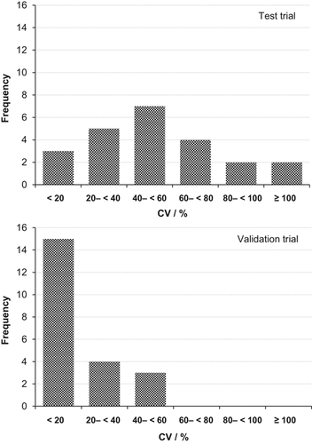
The coefficients of variance illustrate a fairly wide scattering of the single values for the four replications. Most of them (seven values) ranged from 40 to 60%. Three extremely high coefficients of variance (91, 127, and 137%, respectively) were caused by outliers and three CV values were lower than 20%.
3.2 Improving the sampling strategy
3.2.1 Homogenization quality
The homogenization process of the soil monolith samples was evaluated in the improvement trial. The means of the eight replications ranged from 3.6 to 9.3 mg kg−1 for SM 1 and 1.6 to 5.6 mg kg−1 for SM 3, respectively (Fig. 3). For soil monolith 2, which contained the banded slurry, the SMN level was much higher and ranged from about 115 to 248 mg kg−1.
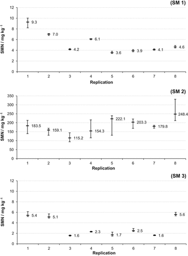
Mean and range of soil mineral nitrogen (SMN = NH4-N + NO3-N) concentrations (mg kg−1) of the subsamples from the soil monoliths of the improvement trial. Whiskers = range; (SM 1) = 0–10 cm depth; (SM 2) = 10–25 cm depth; (SM 3) = 25–30 cm depth.
With only one exception (SM 1, Rep. 1) the range of all subsamples within a single replication was much smaller than 1 mg kg−1 for SM 1 and SM 3. In contrast, the subsample values scattered considerably for the soil monolith samples of the slurry injection zone (SM 2) ranging from more than 40 mg kg−1 up to 119 mg kg−1. An exception was Rep. 7 with only 16 mg kg−1.
3.2.2 Coefficients of variation to calculate the sample size
In order to obtain a representative sample for each location, the necessary sample size per pooled sample had to be determined based on the specification of the sampling variance for SMN (cf section 2.4). For this purpose the coefficients of variance were calculated for each layer and averaged for the entire soil core (0–60 cm) and for the three soil monolith samples (0–30 cm), respectively (Table 3). To achieve this, SMN values for each sampling location were averaged for the entire sampling depth followed by calculating the means for all 64 (auger samplings) and 8 (soil monoliths) locations.
| Depth / cm | n | Mean / mg kg−1 | Min | Max | s | CV / % | |
|---|---|---|---|---|---|---|---|
| AU (ir) | 0–30 | 64 | 7.2 | 2.7 | 17.7 | 3.1 | 44 |
| 30–60 | 64 | 2.6 | 0.8 | 8.4 | 1.6 | 63 | |
| 0–60a | 64 | 4.9 | 2.4 | 12.3 | 2.1 | 43 | |
| SM (1–3) | 0–10 | 8 | 5.4 | 3.6 | 9.3 | 2.0 | 37 |
| 10–25 | 8 | 185.0 | 129.7 | 248.4 | 38.6 | 21 | |
| 25–30 | 8 | 3.2 | 1.6 | 8.0 | 1.8 | 56 | |
| 0–30a | 8 | 94.8 | 66.5 | 126.7 | 19.3 | 20 | |
| AU (bSM) | 30–60 | 8 | 2.0 | 0.8 | 4.3 | 1.24 | 62 |
- aValues for each sampling point were averaged for the entire sampling depth followed by calculating the means for all 64 (auger samplings) or 8 (soil monoliths) locations
For the auger samples from the interrow locations there was no relation between SMN values (both depths) and the row distance (15 or 30 cm). Thus, all interrow locations were combined in one data set [AU (ir), n = 64 to calculate the CV for each depth. That resulted in CV of 44% for the top layer, 63% for the middle layer, and 43% for the entire soil core (0–60 cm), respectively. The CV of the middle layer was confirmed by the CV of the eight auger samples taken below the soil monoliths [AU (bSM)]. For the soil monolith samples, CVs of 37% for SM 1, 21% for SM 2, 56% for SM 3, and 20% for the entire 0–30 cm layer were determined (Table 3).
3.2.3 Changes in SMN along the soil core due to drilling through banded slurry
Results of the test trial indicated SMN changes in soil core samples of the middle layers due to drilling the auger through the previously injected slurry band. Because of the distinctly higher SMN concentrations around the slurry injection zone compared to the middle layer (cf section 3.1), it can be expected that even a slight carryover of slurry components from the injection zone along the soil core leads to incorrect SMN values for the middle layer. To verify this hypothesis, SMN values of the middle layer of 48 auger samples, which were drilled through the previously injected slurry band (AUtsb), were compared with eight unaffected soil cores taken below the soil monolith samples (AUbSM3; Fig. 4).
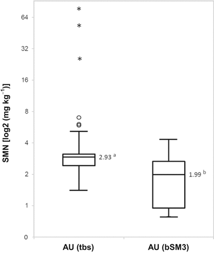
Soil mineral nitrogen (SMN = NH4-N + NO3-N) concentrations (mg kg−1) of the middle layer (30–60 cm) based on 48 augers drilled through the slurry band (AUtsb) in comparison to eight samples taken from below the soil monolith samples (AUbSM3). Boxplots: arithmetic mean without outliers (line inside the box), 1st and 3rd quartile (lower and upper hinge of the box); whiskers: minimum and maximum values; O and * = outliers according to Grubbs (1950) (O = values with a 1.5 to 3 times box height distance to nearest hinge; * = extreme values (distance nearest hinge is more than triple box height)); a/b = significant difference (t-test; P = 5%).
For the AUtsb samples six outliers according to Grubbs (1950) were determined (three of them extreme values), which were excluded from further calculations. The SMN mean of the middle soil layer of AUtsb was 2.93 mg kg−1 and, thus, significantly higher compared to the unaffected samples (AUbSM3) with a SMN mean of 1.99 mg kg−1.
3.3 Validating the sampling approach
The results of the validation trial confirmed the results observed in the test trial (Table 4). Slurry injection again resulted in extremely high SMN concentrations with a mean of 170 mg kg−1 in SM 2 at the first sampling date. SM 3 (23–30 cm) showed also substantially higher SMN concentrations (34 mg kg−1) compared to the other sampling grids. Furthermore, slightly higher SMN values were found for the AU 0 samples in the 30–60 and 60–90 cm soil layers compared to the same layers of AU 15 and 30. In the interrow locations decreasing SMN concentrations with increasing depth were noted. In addition, the SMN level declined with increasing distance to the row.
Until 81 DAI (ten-leaf developmental stage) the SMN concentrations in the slurry injection zone (SM 2) and directly beneath this zone (SM 3) had sharply declined down to 2.2 mg kg−1. Below the monolith samples, the SMN level had increased, resulting in the highest SMN content in the bottom layer of AU 0 (13.2 mg kg−1). With respect to the interrow locations, the SMN concentrations of the top layer decreased, whereas higher concentrations were noted in the middle and especially in the bottom layer (exception: AU 30, middle). The coefficients of variance were mostly lower than 20%. The highest three CV values ranged from 40 to 60%. However, it has to be taken into account that two of them were influenced by outliers.
| Soillayer / cm | Rep. 1 | Rep. 2 | Rep. 3 | Rep. 4 | Mean | s | CV / % | |
|---|---|---|---|---|---|---|---|---|
| Pre-emergence (24 DAI) | ||||||||
| SM (1–3) | 0–8 | 3.0 | 10.2 | 3.8 | 10.0 | 6.8 | 3.9 | 58 |
| 8–23 | 156.2 | 233.3 | 114.4 | 176.0 | 170.0 | 49.4 | 29 | |
| 23–30 | 28.8 | 32.8 | 41.2 | 33.1 | 34.0 | 5.2 | 15 | |
| AU 0 | 30–60 | 4.3 | 4.4 | 6.1 | 6.7 | 5.4 | 1.2 | 23 |
| 60–90 | 1.1 | 1.7 | 1.5 | 1.7 | 1.5 | 0.3 | 17 | |
| AU 15 | 0–30 | 4.7 | 6.6 | 7.9 | 6.9 | 6.5 | 1.3 | 20 |
| 30–60 | 2.3 | 3.0 | 3.3 | 3.4 | 3.0 | 0.5 | 16 | |
| 60–90 | 1.1 | 1.2 | 1.2 | 1.1 | 1.2 | 0.1 | 7 | |
| AU 30 | 0–30 | 4.2 | 4.7 | 5.5 | 5.0 | 4.9 | 0.6 | 12 |
| 30–60 | 2.5 | 3.3* | 2.7 | 2.5 | 2.8 | 0.4 | 14 | |
| 60–90 | 0.9 | 1.2 | 1.3 | 1.2 | 1.1 | 0.1 | 13 | |
| Ten-leaf stage (81 DAI) | ||||||||
| SM (1–3) | 0–8 | 6.0 | 5.8 | 6.7 | 5.7 | 6.1 | 0.4 | 7 |
| 8–23 | 2.5 | 2.2 | 2.2 | 1.9 | 2.2 | 0.2 | 11 | |
| 23–30 | 3.8* | 1.5 | 1.7 | 1.7 | 2.2 | 1.1 | 50 | |
| AU 0 | 30–60 | 10.0 | 9.1 | 6.0 | 11.5 | 9.2 | 2.3 | 25 |
| 60–90 | 12.2 | 12.9 | 12.8 | 14.9 | 13.2 | 1.2 | 9 | |
| AU 15 | 0–30 | 3.7 | 3.0 | 3.2 | 2.5 | 3.1 | 0.5 | 16 |
| 30–60 | 7.1* | 3.6 | 3.2 | 3.7 | 4.4 | 1.8 | 41 | |
| 60–90 | 5.5 | 5.3 | 4.5 | 5.0 | 5.1 | 0.4 | 8 | |
| AU 30 | 0–30 | 2.7 | 2.6 | 2.5 | 2.5 | 2.6 | 0.1 | 2 |
| 30–60 | 2.5 | 2.7 | 2.2 | 2.2 | 2.4 | 0.2 | 9 | |
| 60–90 | 3.2 | 2.8 | 2.5 | 3.1 | 2.9 | 0.3 | 11 | |
The homogenization process was tested for the second soil monolith at both sampling dates in all replications (Fig. 5). At 24 DAI, SMN values of the subsamples of each replication ranged from 2 to 7 mg kg−1 and at 81 DAI from 0.05 to 0.27 mg kg−1. The ranges were mainly less than five percent of the mean values (exception: Rep. 2, 81 DAI).
4 Discussion
The developed soil sampling strategy combines the use of a purpose-built soil shovel (Fig. 2) in the direct range of the slurry injection zone and a standardized auger sampling procedure below this zone and in the interrow space (Fig. 1). This flexible method enables the investigator to obtain a reliable characterization of the spatial and temporal SMN distribution after banded slurry injection.
The results from the test trial show that the soil sampling strategy worked well, because SMN concentrations of the different sampling grids reflect the expected distribution after banded slurry injection. At the first sampling date (23 DAI), the slurry injection zone was characterized by very high SMN concentrations in the second soil monolith. With increasing distance from the injection zone to the interrow space and from top to bottom soil layers SMN concentrations decreased (disregarding the outlier in AU 30, 60–90 cm; Table 2). Until the second sampling date (64 DAI) the SMN concentration in the injection zone (SM 2) clearly declined. This is probably mainly due to vertical displacement of nitrate after nitrification of ammonium applied with the slurry into the middle and bottom soil layers and towards the interrow space (AU 15 and 30) of these layers, because the sandy Wehnen site (88% sand, 3% clay; Table 1) has a high risk of downward water movement. Similar results concerning SMN distribution were found by Clay et al. (1995) after band injection of mineral urea ammonium nitrate (CH4N2O + NH4NO3) fertilizer, by McCormick et al. (1983) after injection of pig slurry, by Sawyer et al. (1990) after injection of beef slurry, and by Zebarth et al. (1999) around the injection zone of mineral ammonium nitrate (NH4NO3) fertilizer.
A basic advantage of using the purpose-built soil shovel is that it is possible to adapt the sampling depth of the single soil monoliths to the trial-individual slurry-injection depth, as done in the improvement and validation trials (cf sections 2.2.3 and 2.2.4). Thus, the complete slurry band can always be sampled in SM 2 (Fig. 1). The overall sampling depth of the three soil monolith samples (SM 1–3) was limited to 30 cm below the surface in these trials to allow a better comparison between the sampling grids of the soil profile in the row within the interrow space. However, in the test trial several problems occurred, which were examined in the following experiments.
4.1 Carryover of slurry components
Unexpectedly, in the test trial the SMN value of the middle soil layer of AU 0, which was drilled through the banded slurry, was considerably higher compared to the third soil monolith at 24 DAI. This was most probably an unintended carryover of slurry components from the injection zone along the soil core into the middle soil layer of AU 0. This hypothesis was examined in the improvement trial. Obviously, the risk of such a carryover is high because the SMN mean of the middle layer of the augers, which were drilled through the banded slurry, is significantly higher compared to the unaffected samples taken from beneath the soil monolith samples (Fig. 4). This is due to the very large differences in SMN concentrations between the injection zone and the soil layers below. McCormick et al. (1983) used a very small-scale sampling method around an injected pig-slurry band. Directly after slurry injection, they found SMN concentrations of nearly 500 mg kg−1 at a distance of 2.5 cm from the center of the banded slurry. Comfort et al. (1988) determined NO3-N concentrations up to 780 mg kg−1 in the direct range of the injection zone of liquid dairy manure 26 DAI. Compared to the SMN concentrations of mostly less than 20 mg kg−1, which can be expected in the middle soil layer (Tables 3 and 4; Comfort et al., 1988), the possible changes of SMN, caused by a small carryover of slurry components along the soil core, are evident. As these results were found in a soil with 96% sand and only 2% clay (Lechtingen site; Table 1), we expect the problem of nitrogen contamination to be even more pronounced in soils with higher clay content. Obviously, drilling an auger through banded slurry for characterization of the spatial SMN distribution has to be avoided.
The high CV (i.e., the high spread in values among the four replications in relation to the mean) for each sampling location of the test trial (Table 2) were problematic. It is questionable that the soil sample is representative; this aggravates finding significant differences between treatments in field trials. It is possible that the homogenization quality was not sufficient or that the sample sizes were too small. The improvement trial was conducted to examine these aspects.
4.2 Homogenization quality
The range of the SMN mean values for the eight replications of soil monolith 1 (3.6 to 9.3 mg kg−1) and 3 (1.6 to 5.6 mg kg−1) of the improvement trial characterizes the heterogeneity of the SMN of the Lechtingen site. In comparison, the range of the subsamples of these sampling locations was rather low (mostly less than 1 mg kg−1; Fig. 3). Thus, the homogenization of the soil-monolith samples (except the center from the injection zone, SM 2) by hand and using a 5-mm sieve was sufficient.
In addition to this site heterogeneity for the Lechtingen field, the range of the SMN mean values for the eight replications of SM 2 (115 to 248 mg kg−1) was influenced by the slurry application accuracy and slurry homogeneity. The scattering of the SMN values for the SM 2 subsamples (whiskers for SM 2; Fig. 3) is even more pronounced. It can be hypothesized that soil-slurry compounds were formed, which require a more intensive homogenization to obtain a representative sample. Based on these findings, the homogenization process was improved by using an electric hand mixer in the validation trial, resulting in a markedly reduced scattering.
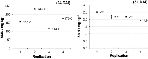
Means and ranges of the soil mineral nitrogen (SMN = NH4-N + NO3-N) concentration (mg kg−1) of the subsamples of the soil monoliths of the validation trial in soil layer 8–23 cm (SM 2). DAI = days after injection.
4.3 Sample sizes
For the calculation of a suitable sample size based on the formula from Gomez and Gomez (1984) (cf section 2.4 and Fig. 6), the following three variables needed to be specified: The coefficient of variation (CV), the significance level (α) and the range of error expressed as a fraction of the mean per plot (d).
Referring to Assefa and Chen (2007) and Zebarth et al. (1999) the significance level (α) was set at 10%. For the auger samples, the CV of the entire soil core [AU (ir), 0–60 cm, CV = 43%; Table 3 was chosen for the calculation, because it is not practicable to differentiate the number of auger samples per soil layer. For the soil monolith samples the CV of SM 2 (SM 2, CV = 21%; Table 3) was used for the calculation, especially because nitrogen transformations around the slurry injection zone were of concern. For the d-value different scenarios are shown in Fig. 6. Regarding soil sampling strategies in field trials, the “fitness of purpose” (Kuchenbuch et al., 2011) has to be taken into account. Therefore, the d-value for the auger samples was set at 20%. This precision level was classified as practical for on-farm testing of SMN distribution by Clay et al. (1995) and Zebarth et al. (1999) and leads to a sample size of twelve auger samples per pooled sample [(I); Fig. 6]. Because of the very high SMN concentration (Tables 2 and 4) around the slurry injection zone at the first sampling after slurry application, a higher precision level with d = 15% is reasonable, leading to six soil-monolith samples per pooled sample [(II); Fig. 6]. These sample sizes were implemented in the validation trial.
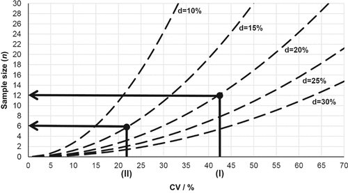
Schematic diagram for the calculation of the suitable sample sizes. (I) = CV of soil mineral nitrogen (SMN = NH4-N + NO3-N) concentration of the soil monoliths (10–25 cm depth) of the improvement trial (Table 3); (II) = CV of SMN concentration of the augers (0–60 cm depth) of the improvement trial (Table 3); d = range of error expressed as a fraction of the mean per plot; CV = coefficient of variance; significance level (P) = 10%.
Lower precision levels with d-values of 25 or 30% would lead to unacceptable imprecision, otherwise d-values ≤ 10% would result in very high sample sizes which are not practical (Fig. 6). If other precision levels are necessary in future trials or other CV will be taken as a basis for the calculation, Fig. 6 allows deducing the appropriate sample size.
To finally evaluate the improved procedure of the homogenization quality for soil sampling, suitable sample sizes (twelve for the auger samples; six for the monolith samples) and the risk for nitrogen carryover along the soil core were implemented into the sampling strategy for the validation trial. Furthermore, soil sampling (Fig. 1) was done in both middle maize-rows per plot to reduce the influence of a possible heterogeneity of the slurry application for a single slurry injection share.
The results of the validation trial concerning SMN distribution agree with the basic results described for the test trial, although SMN level at the Hollage site was somewhat lower compared to the Wehnen site. Due to the implemented measures the spread in values between the replications was considerably reduced. This is evident by comparing the distribution of the coefficients of variation from the test trial with the validation trial (Fig. 7), revealing that this improved sampling strategy is considerably more representative for field situations with localized fertilizer application.
Comparing Figs. 3 and 5, it becomes clear that especially the CV of the auger samples were reduced. However, looking at the samples in the direct range of the slurry injection zone (SM 2), a certain spread in values has to be accepted. For example, the rather high coefficient of variation of soil monolith 1 at the first sampling date (CV = 58%, Table 4) was most probably caused by splashing of slurry in the injection slot during application. That is a basic problem of the slurry-injection technique. At the second sampling date the CV of this grid was only 7%. Overall, the CV of the soil monolith samples were also reduced in the validation trail compared to the test trial. This is due to the clearly improved homogenization process (comparing Fig. 5 to Fig. 3). Compared to the CV presented by Zebarth et al. (1999) regarding soil nitrate concentrations using different sampling strategies after mineral nitrogen side-dressing at the six-leaf stage of maize, the values of the present sampling strategy are markedly lower.
5 Conclusion
The developed soil sampling strategy results in representative soil samples to allow a reliable characterization of the spatial and temporal SMN distribution in soils where slurry has been band-injected. The soil shovel allows a precise sampling of the soil zone with the slurry band and the auger is suitable to sample the interrow space. Furthermore, it is important to intensively homogenize the soil monolith sample including the slurry band and to take a suitable amount of samples per pooled sample. Drilling an auger through the slurry band has to be avoided. The basic methodology and the developed measures to obtain reliable SMN values can simply be transferred to various row crops and slurry injection spacing.
Acknowledgements
We are grateful to the German Federal Environmental Foundation (Deutsche Bundesstiftung Umwelt–DBU) for financing the project “Optimizing the nitrogen and phosphate use efficiencies from liquid manure by slurry injection to reduce environmental pollution”. We acknowledge Chris Bauer (Department of Biology, Drexel University, Philadelphia, USA) for language corrections and Yvonne Garlich (Faculty of Agricultural Science, University of Applied Sciences Osnabrück, Germany) for her help with the field work and in the laboratory.


